AMAZON multi-meters discounts AMAZON oscilloscope discounts
The power supply for a robot is actually several different power supplies. ill. 1 shows examples of the power distribution and transformers for a typical robot. The largest transformer and power supply provide voltage and current for all of the motors and voltage for all other power requirements in the robot. The main transformer for the robot is a multi-tapped three-phase transformer. From the diagram notice that the transformer is tapped so it can receive incoming three-phase voltages of 575, 550, 500, 480, 465, 415/240, or 380/220 AC volts. This allows the robot to be connected to any one of these voltage sources. A second optional user-supplied transformer can also be used to provide voltage for a 120 volt AC utility receptacle, and any other 120 volt requirements. Also notice that the three-phase voltage is first routed through a main circuit breaker that's shown in the top left corner of the diagram. The multi-tap transformer is a means to provide voltage to the robot from nearly any voltage supply that's found worldwide.
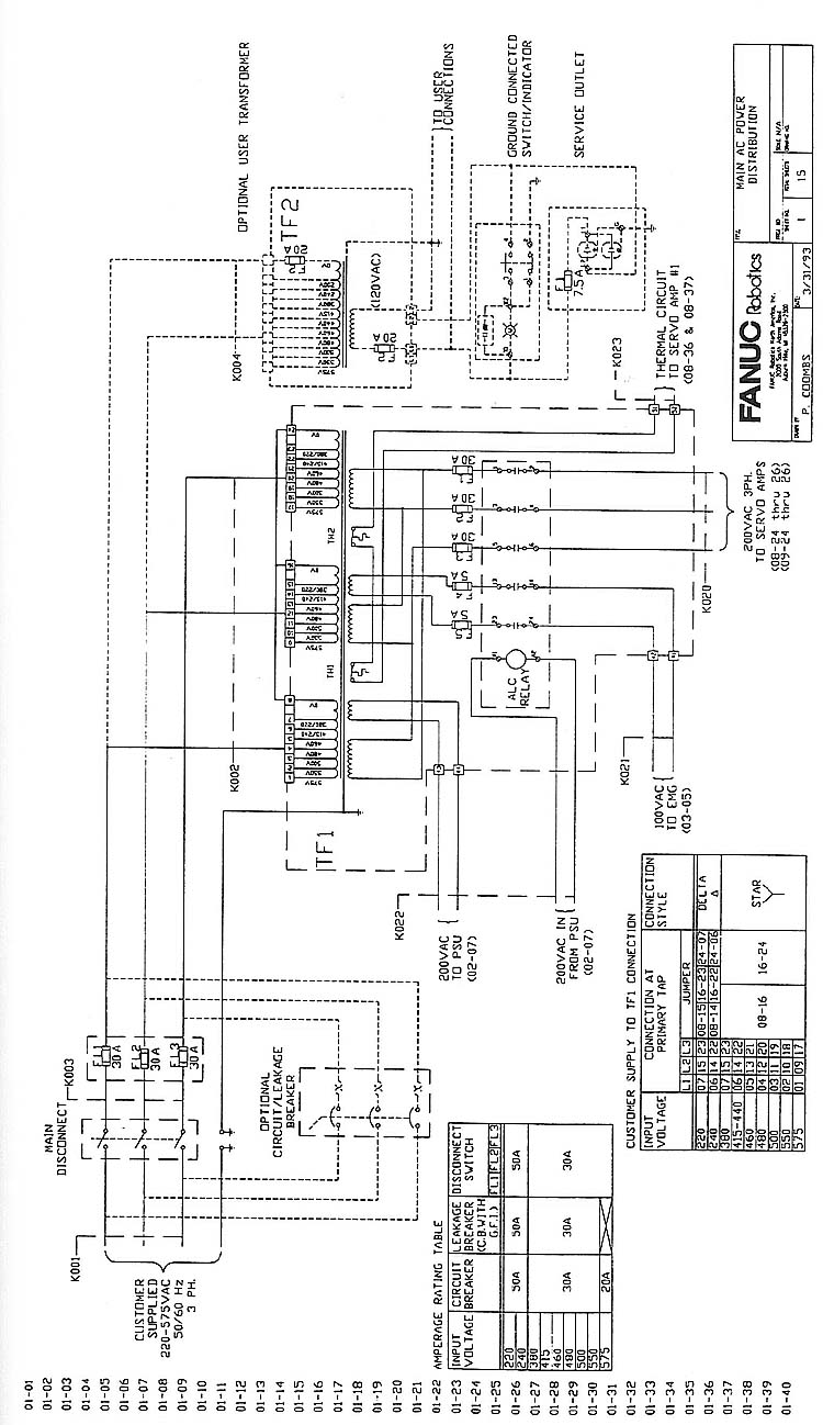
Above: ill. 1 Example of all of the power supplies
for a typical industrial robot. This one is from Faunc Robotics. Click
here or image for full-sized view.
The output voltages for the secondary side of the multi-tap transformer are sent as 230 volt AC three phase to the AC servo amplifiers, and a 230 volt AC single-phase circuit is sent to the power supply unit (PSU) module. A two-wire 110 volt AC circuit is also supplied to the emergency stop board (ENG).
Two circuits are sent to the transformer for safety and control. The first circuit is a thermal protection circuit that feeds voltage through a thermal overload element mounted in the transformer. This circuit is part of the diagnostic system to detect an overheated transformer. A second circuit is sent to the coil of a relay called the power control relay. This relay is shown directly below the main transformer. The signal to the coil comes from the PSU board to indicate the amount of voltage is correct and it's safe to send the secondary voltage to the robot systems. When the coil receives its signal, it closes five sets of contacts, enabling power for all parts of the robot.
The robot may also have several power supplies that are independently mounted throughout the robot cabinet, or they may be par± of a single PSU module. ill. 2 shows a typical PSU module that contains several different power supplies. From the diagram notice that the PSU module provides voltages of + 15 volts and -15 volts as a differential power supply that provides voltage for any analog circuits or op amp circuits, a +5 volt DC power supply that provides voltage for logic circuits, and a +24 volt DC power supply that provides voltage for a variety of internal robot boards and external signals. Additional voltages such as a 12 volt DC or 24 volt DC power supply is usually added by the user for any external signals such as solenoid valves or other interface signals to a PLC or other robots. Typically these power supplies are switching power supplies -- tutorials about their operation may be found on here.
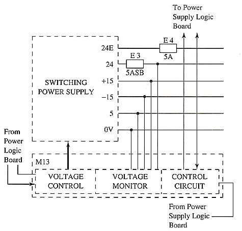
Above: ill. 2: Power supply module and the typical
voltages it supplies. A voltage monitor and control board is used to monitor
input and output voltages for the power supply.
Also notice that there are several control circuits connected to the PSU module. In the diagram notice that a voltage monitor and control board is mounted directly under the power supply. The voltage monitor and control board consists of a voltage control circuit, a voltage monitor circuit, and a control circuit. The voltage control circuit receives its control signal from the PSU logic board. The PSU logic board constantly monitors the incoming power to the power supply and determines if any faults exist. When a fault occurs, this voltage control circuit will receive a fault signal. The voltage control circuit also monitors the output voltage from the PSU module to determine that all of the voltages remain within specifications. If low or high voltage is detected, a fault is generated and the control circuit part of the voltage monitor and control board opens the circuit to protect the robot from these conditions.
| Top of Page | PREV: Basic Parts of Industrial Robot Systems | NEXT: Controllers and Teach Pendants |