AMAZON multi-meters discounts AMAZON oscilloscope discounts
The controller is the name for the cabinet that contains the microprocessor (CPU) for the robot and all of the input and output boards. The teach pendant is connected to the controller main CPU board to provide control of the robot for jogging and programming. ill. 1 shows a typical controller cabinet and ill. 2 shows a typical teach pendant. From the first figure notice that the teach pendant is connected to the controller with a long cable. The long cable allows the technician to be close to the robot end effector when the robot is being programmed. The teach pendant allows the technician to jog the robot or to make changes in the robot program.
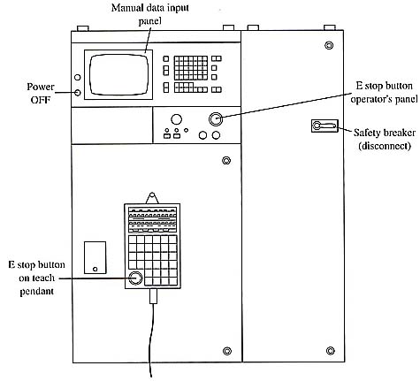
Above: ill. 1: A typical robot controller.
From the diagram of the teach pendant in ill. 2, notice that the teach pendant has an LCD screen to display the information on the robot program, robot position, and input and output signal data the technician needs. The keys on the teach pendant are grouped according to function. For instance, a set of number keys provides data entry for position data and other entries that require numbers. A set of motion control keys is provided to allow the robot to be jogged or moved during set up and programming functions. Sets of program control keys, cursor keys, and menu keys provide functions to allow the technician to move through the robot program and make changes, and a set of function keys (F1-F5) provides a means to interact with screen menu choices.
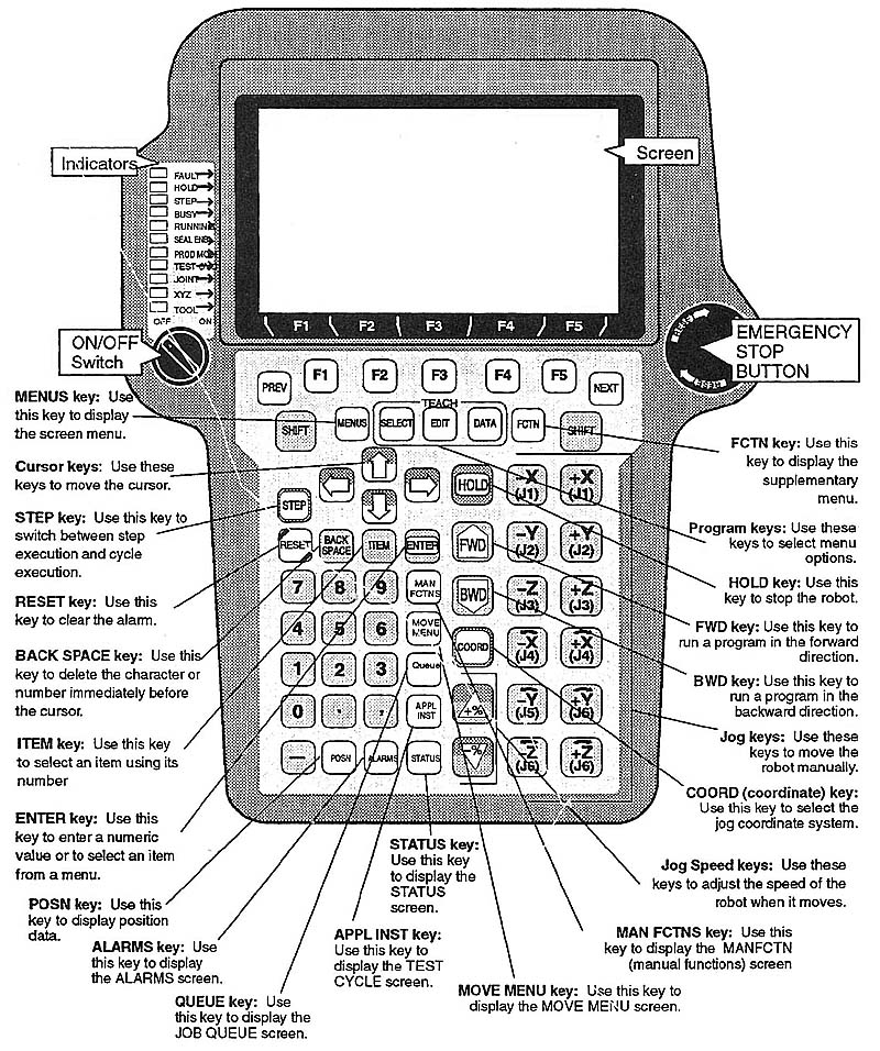
Above: ill.2: Picture of a typical robot teach pendant.
Click here or image to enlarge image.
The teach pendant also has a set of 11 light-emitting diodes (LEDs) on the left side of the screen to indicate alarm conditions. The LEDs will illuminate when problems occur. An emergency stop button is also provided to allow the technician to stop the robot at any time.
ill. 3 shows a detailed cut-away view of a typical robot cabinet. From this diagram of the controller notice that the components in the cabinet are mounted according to their function. For instance, three of the servo amplifiers are mounted in the top left part of the cabinet, and all of the input and output (I/O) modules are mounted in the top right part of the cabinet. The servo modules and I/O modules are rack-mounted modules so that each module can be removed and replaced quickly. All field wiring connections are made with a front-mounted wiring arm that quickly snaps away from the front of each module. That is, when a module is changed, the technician pulls the wiring arm forward so that the module can be removed. After the new module is replaced, the wiring arm is snapped back into place onto the front of the module. With this system the technician doesn’t have to remove and replace any individual wires with a screwdriver.
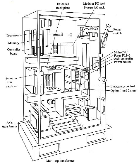
Above: ill. 3: A cutaway view of a robot cabinet.
The middle section of the cabinet contains the main central processing unit (CPU) module, the power supply unit (PSU) module, and the axis control board. These modules are all mounted in their own rack, which makes it easy to remove and replace each if one is suspected of being faulty. This rack has an extended back plane for additional option modules. The right side of the middle section of the cabinet contains additional servo amplifier modules. The exact number of servo amplifier modules will depend on the number of axes the robot has.
The bottom section of the cabinet has the main multitap transformer and the auxiliary transformer. The multitap transformer supplies stepped¬-down voltage for all of the servo amplifiers and the PSU. Voltage is also provided to cooling fans and auxiliary lighting for the cabinet. The three-phase AC voltage supply wires are fed into the robot through the holes in the bottom of the cabinet. These wires are connected to the bus terminals at the bottom of the robot where they are distributed throughout the remainder of the robot and transformers. A disconnect switch is provided on the top right corner of the cabinet. This switch allows all power to the robot to be shut off and locked out while the robot cabinet door is closed. The fuses for the robot panel are mounted in the middle section on the right-hand side where the technician can easily see if they are tripped. Each fuse has a trip indicator to indicate when the fuse has blown.
The controller on some robots has a front panel and a teach pendant through which the operator can enter data and program changes into the robot. In other robots, cabinets don't have a front panel, so the teach pendant is the only interface to the robot. In these systems the teach pendant is mounted in the front panel of the robot when it's not used as a remote device. This allows the teach pendant to function as the front panel. When the teach pendant is removed from the front panel, it allows the operator or technician to get close to the work envelope of the robot to get a close-up view of points where the robot must operate its end effector. For instance, if a robot is used to spot-weld the frame of an automobile, it's important for the technician to be able to have the teach pendant nearby when the points are entered
| Top of Page | PREV: Power Supply | NEXT: Axis Control Module |