| PREV: Using Timers to Stage the Electric Heat | NEXT: Timing and Counting Values Beyond 9999 |
AMAZON multi-meters discounts AMAZON oscilloscope discounts
The counter instruction operates similarly to the timer instruction in the PLC. The major difference between the counter and the timer is the timer instruction will continually increment its accumulative value at a rate determined by the time base when its contacts that enable power to the instruction are closed. On the other hand, the counter must see a complete contact transition from open to close each time it increments the accumulative value. This means that the contacts must also return to their open state before they can transition for a second time. It is important to note that the counter does not care how long the contacts stay closed once they transition; it only looks for the transition. ill. 18 below shows the instruction for a counter that includes reset operation.
AMAZON multi-meters discounts AMAZON oscilloscope discountsThe counter has preset and accumulative values like the timer. The preset value is the desired value for the counter and may represent how large a value the counter is expected to count. The maximum preset value for the counter is 9999. The counter also has several outputs under its control. When the AC value equals the PR value, the status bit goes HI. The status bit controls all NO and NC contacts that have the same number as the counter. The counter also has a bit that indicates if the counter is in an overflow state or an underflow state. The counter is in an overflow state if the AC count tries to exceed 9999, and the underflow s occurs if the AC count tries to go below 0. The overflow and underflow condition set the same bit in the counter. The bit address is determined by adding 50 to the counter address. E.g., if the counter address is 902, the overflow bit would control any contacts that have the address of 952.
The counter has a reset instruction like the timer, which will cause the PR value to return to its original value. When the up-counter instruction is used, the PR value will start at zero, and when the down-counter instruction is used, the PR value will start at its PR value and end at zero. The counter status bit will energize when the PR value equals the AC value for an up counter and when the AC value equals zero for the down counter.
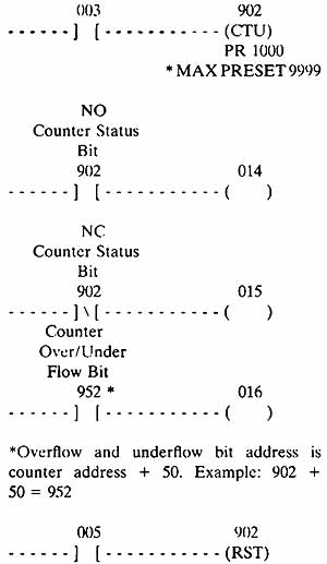
ill.18: Example of a typical counter instruction and its reset.
NO and NC status bits are shown with overflow and underflow bits.
Using an Up / Down Counter to Count Good and Bad Parts
Counters are used to count up, count down, and to provide reset functions. The Allen-Bradley SLC 100 provides separate up-counter (CTU) and down-counter (CTD) instructions. The reset instruction operates like the reset for the timer instruction. The counter instructions share the same memory location in the PLC as the timers, which means that they share addresses 901—932. Another important point to remember is that since timers and counters reside in the PLC memory, they never break down. When a timer in a PLC will not time, or if a counter will not count, you should suspect the inputs to the timer or counter are not transitioning, or the reset line is held HI, but you should not suspect that the timer or counter instruction is broken. You may also find the PLC has lost all or part of its program from its memory and the program will need to be reloaded.
The up counter and down counter both use the PR and AC values like the timer. The up-counter instruction will add 1 to the AC value in the counter each time the instruction is transitioned, and the down-counter instruction will subtract 1 from the AC value.
Using Counters in the Carbon Brush Application
The application program for the carbon brush process system uses up-counter and down-counter instructions that are addressed to the same counter. A photoelectric switch at address 008 detects all of the brushes as they pass into the oven. These contacts are used as the input to the up counter in rung 10 and they count each brush. All of the brushes are weighed as they pass out of the oven, and any that are too light or too heavy are detected by the solid-state scales. The contacts for the solid-state scales are numbered 009, which are used as the input to the down counter in rung 11. Since the up counter counts all parts and the down counter subtracts all of the bad ones, the AC value in counter 902 will represent the good parts. Anytime the counter needs to be reset, a manual push button at address 010 in rung 16 must be depressed by someone responsible for quality control. Push button 010 could be a key-lock switch if security is needed.
Using a Resetting Counter Application
Another useful function that counters provide in industrial applications is the ability to keep track of steps in a sequential operation and reset automatically on the final step. An example of this type of application is counting the brushes as they exit the process oven and grouping them to be packaged four per pack. Although this counter is not part of the main program ( see ill. 19), it could easily be added if a packaging function was required. In this example counter 905 has a preset value of 4, which represents the four brushes that will be grouped and wrapped in a plastic wrapper. Each time a brush is counted, contacts 101 are closed momentarily and then opened, which causes the counter to increment. When the fourth brush has been counted, the contacts transition for the fourth time and the counter AC value will reach its PR value. This means the counter is done and its status contacts 903 in the second rung will be closed and energize the wrapper solenoid. This causes the wrapping machine to wrap the four brushes. The NO 903 contacts in the third rung will energize the reset (RST) instruction for the counter and the counter AC value will return to zero and the counter will be ready to count the next four brushes. Since the wrapper solenoid in the second rung will only be energized for one scan cycle (approximately 20 msec), the wrapper machine must have a seal-in feature that allows it to continue its operation after its input is strobed.
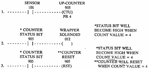
ill.19: An example program of a counter used to count four
parts for packaging. When the four parts are counted, an output
pulse is sent to the wrapper machine. *STATUS BIT WILL BECOME HIGH
WHEN COUNT VALUE = 4; *STATUS BIT WILL BECOME HIGH WHEN COUNTER
VALUE = 4; **COUNTER WILL RESET WHEN COUN VALUE =4
| Top of Page | PREV: Using Timers to Stage the Electric Heat | NEXT: Timing and Counting Values Beyond 9999 |