| PREV: Operation of the Heat-Treating Part of the System | NEXT: Counter Operation in a PLC |
AMAZON multi-meters discounts AMAZON oscilloscope discounts
The electric heating elements for the heat-treating part of this machine are energized in two stages. The logic for staging the heating is shown in rungs 3, 4, 5, and 6 in the diagram in ill. 14. A time delay is needed to allow a 20-second delay between the time the first-stage heating element is energized and when the second-stage heating element is energized. The time delay is necessary to prevent the oven from becoming too hot too quickly. Since the first element is allowed to energize 20 seconds prior to the second element, the oven will begin to heat up slowly prior to having full heat applied.
AMAZON multi-meters discounts AMAZON oscilloscope discounts 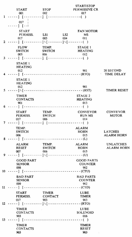
ill.14: Ladder logic for the heat-treating section of the carbon
brush manufacturing system. 20 20 SECOND TIME DELAY; TIMER RESET; CONVEYOR
MOTOR; LATCHES ALARM HORN; UNLATCHES ALARM HORN
In rung 3 the contactor for the first-stage heating element is energized if two conditions are met. First, contacts 005 from the air flow switch must be energized, which indicate the fan motor is energized and proper air flow has been achieved. (The air switch is mounted near the fan so that it will be activated when air is moving.) Second, the oven temperature must be less than 180°F, since the temperature switch 006 is set to open its contacts at this temperature.
The control logic for this system involves electrical control and physical function. This means that even though there is no electrical connection between the start/stop circuit and the electric heat, they are connected by the physical interaction between them. The electric heat is controlled indirectly by the start/stop circuit, since the coil for the first-stage heating contactor in rung 3 can't become energized unless the fan motor is running.
RTO Timers
The SLC 100 uses the mnemonic RTO to represent the retentive timer on-delay. The retentive timer will operate like the traditional hardware motor-driven timer discussed in Section 2. ill. 17 shows more information about the timer instruction. Here you can see that the timers use addresses 901 - 932. Each timer has a preset value (PR value) and an accumulative value (AC value). The preset value is the amount of time delay the timer will provide and the accumulative value is the actual time delay that has accumulated since the timer has been energized. The timer accumulative value increments at a rate determined by the time base. The time base for the SLC 100 timers is 0.1 second. When the timer AC value equals the PR value, the timer times out, and all of the contacts under its control (contacts that have the same address as the timer) will become activated and change state.
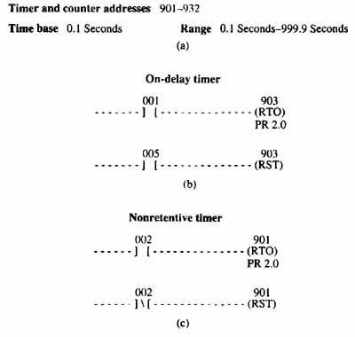
ill.17 (a): Information about timer address or counter addresses,
the time base for timers in the SLC 100, and range for timer preset
values. (b) RTO timer instruction used as on-delay. (c) Making,
a non-retentive timer from an RTO instruction.
Another important part of each timer is the reset function. Each timer must be reset at some point to be used for the next timing cycle. The timer is reset by the RST instruction. The RST instruction must have the same address as the timer to provide the reset function for that timer. E.g., if the timer has an address of 903, its RST instruction must also have the address 903. When RST 903 is energized, the AC value of RTO 903 is reset to 0.
The RTO timer is retentive since its AC value will be frozen and retained in the memory address anytime power to the timer instruction is interrupted. When power is applied to the timer, it will pick up the time delay exactly where it left off and resume the time delay. ill. 17b shows a method to make the RTO timer act like a non-retentive timer. This diagram shows a set of NO 012 contacts energizing the RTO instruction, and a set of NC 012 contacts connected to the RST for the timer. Anytime the 012 contacts are opened to stop the timer, the NC set connected to the RST will cause the timer to reset and return its AC value to 0.
The operation of the RTO timer in the heat-treating system is shown in rungs 4, 5, and 6. After the coil of the first-stage heating contactor (output 012) is energized in rung 3, its contacts are used again in rung 4 to energize timer 901. Since NO contacts 901 are used in rung 6, they will pass power to the second-stage heating contactor (output 013) after timer 901 times out.
The SLC 100 also provides an off-delay timer with the RTF instruction. The RTF operates exactly like a motorized off-delay timer. The accumulative time will not begin to increment until power has been applied to the instruction and then de-energized. The RTF instruction begins its operation when the transition from on to off occurs. The contacts for the off-delay timer can be normally open or normally closed.
Using the RTO As an Automatic Resetting Timer for Lubrication
Rungs 12, 13, and 14 use an RTO timer that automatically resets itself with a lubrication system solenoid. The automatic resetting timer function is used in this application to provide automatic lubrication at a fixed time period. The automatic reset part of this circuit is accomplished by using an RTO timer instruction and placing a set of the NC timer contacts in series with it, and placing a set of NO timer contacts in series with the timer reset instruction. Since the RTO 903 instruction has a set of NC contacts to energize it, it will begin the cycle by receiving power. Every 60 seconds the timer will close the NO 903 contacts in line 13 of the program to energize the lube solenoid and close the NO 903 contacts in rung 14 that provide a signal to the timer RST instruction. The RST instruction will cause the timer to reset and start its timing cycle again automatically. It is important to understand that the lube system only needs its solenoid pulsed to activate the lubrication system.
| Top of Page | PREV: Operation of the Heat-Treating Part of the System | NEXT: Counter Operation in a PLC |