| PREV: Other Sequencer Functions | NEXT: Wiring Input Switches and Output Devices to the PLC |
AMAZON multi-meters discounts AMAZON oscilloscope discounts
At times you will need to connect a wide variety of switches to input modules and a wide variety of output devices to output modules. It will be necessary to understand the electronic circuits inside these modules that provide the signal conversion and the devices that provide circuit isolation. ill. 26 shows the electronic circuits for an ac voltage input module, an ac voltage output module, and the relay output module. The circuit for the ac voltage input module is shown in ill. 26a. From this diagram you can see that the circuit represents a single circuit in the module. Typical modules will have 2, 4, 8, 16, or 32 of these circuits that will all be the same. The circuit has two terminals for the input signal to be connected: the line ac hot and the ac common. The switch that's being monitored by the module would be connected in series with the ac hot terminal. This means that Li voltage from the ac power supply would have to be connected to the switch so that when it closes, it would pass this voltage to the ac hot terminal of the module. The L2 voltage from the ac power supply would be connected directly to the ac common terminal on the module. If the module has multiple circuits, the common voltage can be jumpered from common terminal to common terminal for each circuit.
AMAZON multi-meters discounts AMAZON oscilloscope discounts 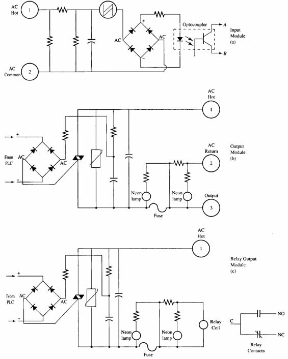
ill.26: (a) Electronic circuit for a 110 volt ac input module. (b)
Electronic circuit for 110 volt ac output module. (c) Electronic circuit
for relay output module.
When the switch that's connected to the ac hot terminal is closed and passes voltage to the input part of the module circuit, the voltage passes through the resistive network that will drop the 110 volts to a lower voltage. The lower voltage flows through the bridge rectifier where it's turned into pulsing dc voltage. The pulsing dc voltage flows through the light-emitting diode (LED) part of the opto coupler. When the LED has current flowing through it, it produces a light that's focused directly on the base of the phototransistor mounted inside the optocoupler. The phototransistor will go into conduction when light is focused on it and signal current will flow through its emitter-collector circuit into the input bus of the PLC. When the PLC receives the signal, a 1 is written into the image register during the next scan cycle.
Electronic Circuit for a 110 AC Output Module
ill. 26b shows the electronic circuit for a 110 volt ac output module. From this diagram you can see that each circuit has three terminals: the ac hot and ac return (common) that supply voltage to power the module, and the terminal for the output signal. The circuit for the output module uses a bridge rectifier and a triac to convert the low voltage dc signal from the PLC bus to control an ac output voltage signal of 110 volts. This is a unique circuit because the bridge rectifier is generally thought of as a device that converts ac voltage to pulsing dc voltage. In this circuit the bridge rectifier is going to act as a switch for the ac current. When the ac hot and ac return are applied to the circuit, voltage will flow completely through the circuit until it reaches the triac. The triac is an electronic device that will act like an open switch until it receives a pulse on its gate. (Google the “operation of the triac” for more detail.) When the triac receives the gate pulse, it will go into conduction and pass the voltage signal on to the output terminal of the circuit. The pulse for the triac gate is supplied by ac current flowing through the bridge rectifier. If the dc voltage side of the rectifier does not have current flow, the ac side will not have current flow. When the PLC sends a signal from its output bus to the module, it will allow current to flow on the dc side of the bridge, which will allow the ac voltage to flow through the bridge and provide a signal to the gate of the triac.
When voltage flows through the triac, it will move on to the output terminal of the module. The output section of this circuit has a neon indicator lamp connected so that it will illuminate anytime voltage is present at the output terminal. This indicator lamp is called the status indicator since the troubleshooting technician can look at it and quickly determine if the output circuit is receiving power. Some modules use an LED instead of a neon indicator lamp. You should also notice a fuse is connected in series with the output signal. A second indicator lamp is connected to this part of the circuit to indicate the fuse has blown. If the fuse is good and providing a current path, the neon indicator will not receive enough voltage to illuminate, and if the fuse blows (opens) a small amount of current will flow through the indicator lamp and it will illuminate to indicate a fuse has blown.
Electronic Circuit for the Relay Output Module
The electronic circuit for the relay output module is shown in ill. 26c. From this diagram you can see that the circuit for this module is very similar to the regular ac output module except the relay output module has a small relay mounted in the circuit board where its coil can be connected directly to the output circuit. The relay provides a set of NO and NC contacts with a single common point. The contacts provide complete isolation from all voltages in the PLC and in the module. This means that the output signal from the PLC will act to open or close the relay contacts.
The relay contacts are used quite frequently in applications where the PLC must provide signals to a variety of other electronic devices such as input signals to robots. It is possible to have one robot that uses a current sourcing signal as an input, while two others use current sinking and low-voltage dc. This means that three different types of output modules would have to be used or several separate signal conditioning circuits would have to be made to accommodate all of these signals. The isolated contacts of the relay output module allow each robot to use its own power supply to send voltage to one side of the relay contacts, and when the contacts close, the signal is sent back to the robot as an input. This means each robot will receive the correct voltage at the correct polarity without interfering with other devices that are also connected to the PLC. Since the relay output module has both open and closed contacts available, differences in signal logic can also be accounted for, since some electronic devices look for the input signal to transition from on to off, while normally they look for the transition from off to on.
| Top of Page | PREV: Other Sequencer Functions | NEXT: Wiring Input Switches and Output Devices to the PLC |