| PREV: Circuits for Input and Output Modules | NEXT: Analog Input Modules |
AMAZON multi-meters discounts AMAZON oscilloscope discounts
All of the inputs and outputs that are used in the PLC system must be connected to the input or output module hardware. ill. 27 shows an example of wiring a push-button switch to an input address and a motor starter coil connected to an output address. From this diagram you can see the location of the screws on the SLC 100 and where the wires from the switch and coil for the motor starter are connected.
AMAZON multi-meters discounts AMAZON oscilloscope discounts 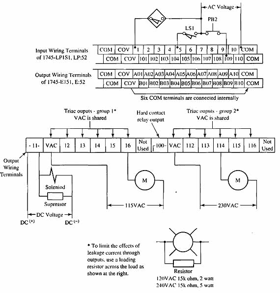
ill.27: Wiring a push-button switch to an input module and wiring
a motor starter to an output module of an SLC 100.
When the switch that's connected to the ac hot terminal is closed and passes voltage to the input part of the module circuit, the voltage passes through the resistive network that will drop the 110 volts to a lower voltage. The lower voltage flows through the bridge rectifier where it's turned into pulsing dc voltage. The pulsing dc voltage flows through the light-emitting diode (LED) part of the opto coupler. When the LED has current flowing through it, it produces a light that's focused directly on the base of the phototransistor mounted inside the optocoupler. The phototransistor will go into conduction when light is focused on it and signal current will flow through its emitter-collector circuit into the input bus of the PLC. When the PLC receives the signal, a 1 is written into the image register during the next scan cycle.
The hard-wired circuit of a PLC must also be protected by a real relay called a master control relay. This relay will be identified as CRM (control relay master) in the diagram shown in ill. 28. In this diagram you can see that all of the voltage to the input and output modules is controlled by the contacts of the CMR. The coil of the CMR is connected to a start/stop push-button station. This allows the power to be shut off to the inputs and outputs by depressing the stop button. You should notice from this diagram that power is connected directly to the processor.
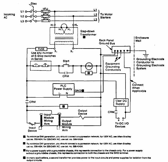
ill.28: Electrical diagram of the master control relay that's used to disconnect power to all inputs and outputs. Notice the
relay in the diagram is identified as CRM (control relay master).
To minimize EMI generation, you Should connect a suppression network: for 120V AC, us. Allen-Bradley cat. no. 700-N24; for 220/240V AC, use cat, no. 599-KAO4.
• To minimize EMI generation, you should connect a suppression network: for 120V AC, use Allen-Bradley cat. no. 599-1 for 220/240V AC, use cat. no. 599-KAO4.
• For a power supply with a groundable chassis, this represents connection to the chassis, only. For a power supply without a groundable chassis, this represents connection to both the chassis and the GNO terminal.
• In many applications, a second transformer provides power to the input Circuits sod power supplies for isolation from the output circuits.
| Top of Page | PREV: Circuits for Input and Output Modules | NEXT: Analog Input Modules |