| PREV: Analog Input Modules | NEXT: Using the Hand-Held Programmer |
AMAZON multi-meters discounts AMAZON oscilloscope discounts
There are times when the PLC controlled system needs to have a select number of its outputs de-energized immediately regardless of the condition of the logic for the rung. E.g., if a system has a number of pneumatic cylinders that are used to move boxes onto a conveyor, at times the boxes have a tendency to get caught between cylinders. If the voltage to the pneumatic control valves can be de energized, each of the valves may be plugged, which means they can be switched manually by depressing their actuators with a screwdriver. If voltage remains on the solenoid coil, the valve can't be manually switched.
AMAZON multi-meters discounts AMAZON oscilloscope discountsThe PLC provides a function called master control reset (MCR) that has the power to dc-energize a group of outputs (see ill. 29). The MCR function consists of two MCR output coils. The first MCR output is placed in the rung ahead of the outputs that are to be dc-energized, and the second MCR output is placed in the rung after the outputs that are to be controlled. This builds a fence or barrier around the rungs having the outputs that are to be dc-energized by the MCR.
When the contacts in series with the first MCR apply power to it, the MCR allows the outputs to operate in the normal condition so that they will respond to the logic condition of the rung they are in. If the contacts that enable the first MCR to open and dc-energize the MCR, it will immediately dc-energize all output coils between it and the second MCR instruction. The MCR acts like a programmable master control relay that's used for emergency stop conditions.
It is important to point out at this time that the National Electric Code (NEC) requires a hard-wired electromechanical relay to be used to dc-energize power to all output as in a traditional relay controlled system. This means the MCR instruction can be used in addition to the real hard-wired relay, but it can't be used instead of the real relay. A table is also provided in the figure to indicate how the MCR affects all other instructions.
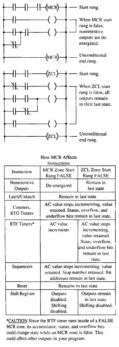
ill.29: Example of master control reset (MCR) and zone control
last state (ZCL) instructions. The table indicates the condition of all
outputs that fall under control of these instructions. *CAUTION: Since
the RTF timer runs inside of a FALSE MCR zone, its accumulator, status, and overflow bits could change state while an MCR zone is false. This
could affect other outputs in your program.
The zone control last state (ZCL) instruction provides a similar function to the MCR. The ZCL uses two output instructions to set up a barrier around a number of rungs that are to be controlled. When the first ZCL rung is false, the zone control instruction freezes all of the outputs inside the zone to their last state. This means that all outputs in the zone that are on will remain energized, and all outputs in the zone that are off will remain dc-energized. One function of using the ZCL instruction is to provide a means to use outputs more than once in a program. This programming feature is especially useful where the program has multiple functions such as a pallatizing system that can pack 4, 8, or 12 boxes per layer.
| Top of Page | PREV: Analog Input Modules | NEXT: Using the Hand-Held Programmer |