AMAZON multi-meters discounts AMAZON oscilloscope discounts
ill. 1 shows two typical circuits found in robots for output signals. ill. 1a shows the circuit for a current-sink circuit. Note in this diagram that a 24 volt DC power source is needed for the circuit. The electronic circuit in the robot basically switches this power source on or off for the output device. The + terminal of the power supply is connected to terminal 2, and the - terminal of the power supply is connected to the common terminal identified as terminal 20. The load (such as a relay coil) should be connected between the center terminal and the common terminal.
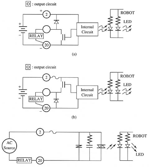
Above: ill.1 (a) A sink-current output module. (b)
A source-current output module. (c) An output module for 120 volts AC.
The circuit consists of an opto-isolation circuit that uses an LED to provide the light to activate the circuit. When the robot sends an output signal from its bus, it will flow through the LED, which will cause it to illuminate and the light will activate the remainder of the circuit. When the circuit is activated, a solid-state device will allow current to flow to the output terminal of the circuit and through the load. A second LED is provided on the robot side of the circuit to illuminate as a status indicator to show that the signal is energized.
ill. 1b shows the diagram of a current-source output circuit for a robot. The main difference between the current-source and the current-sink circuits is the way the current is switched to allow the polarity to be correct with the output device. If the device that receives the output signal is a relay coil, the polarity of the signal won't matter. But if the output signal is sent to another robot that expects a current-source input signal, one must use the current-source output module to ensure that the signal will interface correctly. It's important to understand that the wide variety of solid-state devices that's interfaced with robots and PLCs will require that the signal types be matched correctly, or the signals won't be transmitted correctly.
ill. 1c shows the diagram of an output circuit for a robot that can send
120 volt AC signals. From this diagram notice that the circuit uses a
triac in the output section to accommodate the AC signal. The power source
for this circuit is 120 volts AC and the output device (relay coil) is
connected in series with terminal 4 and the voltage source. When the robot
sends an output signal to the LED, it will illuminate and cause the triac
to go into conduction, allowing AC current to flow to the output device.
Notice that a variety of input and output modules is available for robots
to ensure that they can have their signals interfaced to virtually any
other electronic device or circuit in any industrial application.
| Top of Page | PREV: Input Circuits for Industrial Robot Signals | NEXT: Input and Output Modules |