AMAZON multi-meters discounts AMAZON oscilloscope discounts
ill. 1 shows examples of four types of circuits that are used in input modules to receive input signals. The diagram in ill. 1a shows a circuit for a 24 volt DC source-current input. A switch is used only to indicate the side of the circuit where the input signal is coming from. This type of circuit expects the input terminal I to see +24 volts DC. Notice that the +24 volt DC signal will cause the LED status indicator and the LED in the opto-coupler to illuminate. This signal can come from a switch in the work cell area, another robot, or from a PLC. When the LED in the opto-coupler illuminates, it produces sufficient light to bias the phototransistor, which will allow current to flow through its collector-emitter circuit into the robot. The opto-coupler provides isolation between the external input signal and the robot's internal circuits.
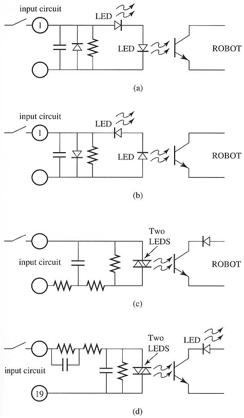
Above: ill.1 (a) Current-source circuit for 24 volt
DC input to a robot. (b) Current-sink circuit for 24 volt DC input to
a robot. (c) Input circuit for 24 volt DC current-source or current-sink
signal. (d) Input circuit for 120 volt AC signal for a robot.
The diagram in ill. 1b shows the circuit for a sink-current input. In this circuit, the input signal to terminal 1 must be -24 volts DC. Note that the LED used as the status indicator and the LED in the opto-coupler are connected in reverse direction of the ones in the source-current circuit. The opto-coupler also provides isolation in this circuit. It's important to understand that when one must use the output signal from another robot as the input signal of your robot, one may not be able to change the type of DC signal from current source to current sink. One will have to select the proper input module for your robot so that the signal will interface properly. This problem also occurs in some smaller PLCs that don't have a choice of output modules, and one must live with the signal it sends the robot, selecting the proper module (current sink or current source) so that the signal will interface properly.
ill. 1c shows a diagram of an input circuit that can receive either a
current-source or a current-sink signal. This type of input module would
be used if one has a variety of both current-source and current-sink signals
that must be connected to the same robot and one doesn’t want to purchase
both a current-source input module and a current-sink input module. This
circuit uses an opto-coupler that has two LEDs connected back to back
in parallel. This arrangement allows one of the LEDs to illuminate if
the signal is current sink, and the other will illuminate if the signal
is current source.
The diagram in ill. 1d shows an input circuit for 120 volt AC input signals.
This circuit uses several resistors to drop the voltage as it enters the
circuit, and it also uses an opto-coupler that has the same arrangement
of its LEDs as the previous circuit. Since the LEDs are connected in inverse
parallel to each other, they will illuminate anytime an AC signal is sent
through it. The opto-coupler provides circuit isolation between the AC
input and the robot's internal circuitry. The input voltage of this circuit
is 120 volts AC, which is generally used in all input (pilot) devices
such as limit switches, push-button switches, and other control switches.
Some factories prefer the 120 volt signal because this higher-voltage
signal will work even when the contacts of the switches begin to become
dirty or pitted.
| Top of Page | PREV: Input and Output Signals for Industrial Robots | NEXT: Output Circuits for Industrial Robot Signals |