AMAZON multi-meters discounts AMAZON oscilloscope discounts
The sump pump could become more automated if a microprocessor controller was used as the controller. A liquid-level sensor is used to indicate the level of the liquid in the sump instead of the float. The sensor sends a voltage signal to the controller to indicate the exact level of the liquid in the sump. This is the process variable (feedback) signal. An operator must enter a number into the controller to indicate the desired level (setpoint) for the liquid in the sump. The controller compares the setpoint and the process variable, and the difference between them is the error.
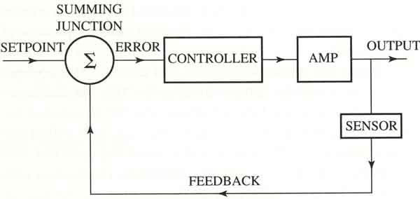
A process control diagram was previously presented in ill. 1 (below). In this figure notice the setpoint (SP) and the process variable (PV) are compared in the controller at a point called the summing junction (Σ). The error signal comes from the summing junction and represents the difference between the SP and the PV. The error signal can be positive or negative depending on whether the actual level is higher or lower than the SP. The controller uses the error signal to determine when to turn on the output (pump motor). The controller calculates the error continually and when it determines the liquid level is above the SP, it will send a signal to turn on the pump. As the liquid level is pumped down, the controller calculation at the summing junction will determine that the level is below the SP and send a signal to turn the output off.
PREV: Adding Differential Gap (Dead Band) to the Sump Pump Application
NEXT: Single-Point (Single-Loop) Process Controller