AMAZON multi-meters discounts AMAZON oscilloscope discounts
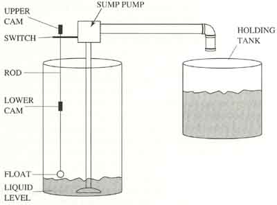
The sump pump application can be described in several ways, which may be confusing at first, but eventually you will begin to see why each description is necessary as more information is provided in this section. First, it may be called a closed-loop system because the float and switch mechanism will turn the pump on automatically when the level in the sump is high, and turn off the pump when the level becomes low again. The system may also be referred to as a simple on-off control system because the pump motor can only be energized where it's running at 100%, or it can be de-energized where it's not running at all.
A differential gap can be designed into the sump pump system by modifying it so that it has two cams attached to the float rod. ill. 5a (below) shows an example of two cams set for a small differential gap and ill. 5b (below) shows an example of two cams set for a large differential gap. The points on the rod where the upper and lower cams are set are called the setpoints. If the upper cam is moved higher, the level of the liquid will be allowed to fill to a higher level before the pump is turned on. If the lower cam is set lower, the level in the sump will be allowed to go lower before the pump is turned off.
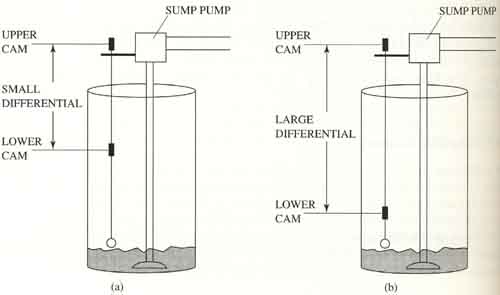
Above: ill. 5 (a) Two cams set for a small differential for the sump
pump application. (b) Two cams set for a large differential for the
sump pump application.
The distance between the upper and lower cam on the rod is called differential gap or dead band. If the distance between the upper cam and the lower cam is increased, the differential gap (dead band) will be larger. The larger the dead band, the larger the difference will be between the highest and the lowest levels the liquid. If the differential gap is large, the motor will not cycle as quickly and it will remain running longer once it's energized. The only drawback to a larger differential gap is that the level in the sump will vary from nearly full to nearly empty. This isn't a problem with the sump pump application because the pump is trying to keep the sump empty. The differential gap would have to be smaller if the control system is used to control the level of water for a mixing application where the control system is used to measure the amount of water or level in the tank. In this type of control the amount of water needs to be controlled to a specific level, and a small differential gap would accomplish this.
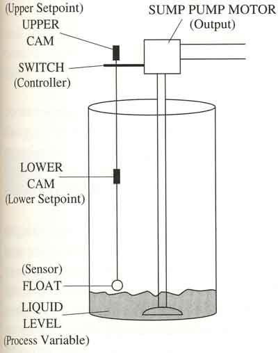
It's also important to be able to identify the basic parts of the process system such as setpoint (SP), process variable (PV), sensor, controller, and output for each system that you encounter. ill. 6 (below) shows these parts identified for the sump pump application. The upper cam is the upper SP, and the lower cam is the lower SP. The PV in this system is the liquid level and the float is the sensor that indicates the liquid level. Since the float sends the signal that indicates the level of the liquid in the sump to the switch, the sensor signal will be called the PV signal. The switch is the controller in this system and the pump is the output device or final control element that can change the liquid level by pumping the liquid into the holding tank and lowering the liquid level in the sump.
PREV: On-Off Control
NEXT: Automating the Sump Pump Application