AMAZON multi-meters discounts AMAZON oscilloscope discounts
Another rather simple system can be used to explain the major difference between open-loop and closed-loop control. In this control system a sump pump is turned on to pump out a sump when the level of the liquid in it gets too deep. Many industries have a sump, which is a large hole in the floor that collects waste water or waste cutting oil. When the liquid level in the sump rises enough, the liquid must be pumped out of the sump into a holding tank. If this system was an open-loop system, someone would have to periodically check the level of the sump and turn the pump on when the level gets too high. When the pump lowers the level sufficiently, the pump would be manually turned off.
In a closed-loop system, a sensor would be connected to the switch mechanism to turn the pump on and off automatically. This sensor and control mechanism could be something as simple as a float that's mounted on the bottom of a rod. In ill. 4 (below) notice that the rod is mounted on the sump pump and it activates the switch when the float moves the rod up or down with the liquid level. Two cams are attached to the rod at the point where the rod goes through the pump switch activator. One of the cams is attached to the rod just above the switch arm and the other cam is connected to the rod just below the switch arm.
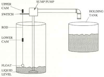
Above: ill. 4: Sump pump application.
When the liquid level rises in the sump, the float will move up with the level and the lower cam will force the switch arm up to turn the pump on. When the pump begins to pump the liquid into the holding tank, the level in the sump lowers, the float will move down, and the cam that's mounted on top of the switch arm will press the switch arm down to turn off the pump. When the liquid level rises again, the float will rise and turn on the switch again, and the process is repeated again. The float and rod provide the process variable (feedback) signal for this system.
PREV: Manual Mode and Auto Mode
NEXT: On/Off Control