AMAZON multi-meters discounts AMAZON oscilloscope discounts
FLASH HAZARD CALCULATIONS AND APPROACH DISTANCES
Caution: all of the formulas, methods, and calculations discussed in this section are based upon regulatory standards and engineering practices that are in use as of July 2011. a great deal of research work has been and is currently under way; consequently, current literature and a competent, qualified engineer with sufficient background and experience should be consulted to verify that these methods are still the recognized approach.
Introduction
How close to an electrical hazard can I get? Obviously, distance provides a safety barrier between a worker and an electrical hazard. As long as workers stay far enough away from any electrical energy sources, there is little or no chance of an electrical injury. This section describes methods that can be used to determine the so- called approach distances. Generally, if work can be carried on outside the approach distances, no personal protective equipment is required. If the worker must cross the approach distances, appropriate personal protective equipment must be worn and appropriate safety procedures must be used.
Approach Distance Definitions
Approach distances generally take two forms-shock hazard distance and flash hazard distance. Note that the flash or arc hazard distance also includes the blast hazard distance.
FIG. 35 illustrates the approach distances that are defined by the NFPA in its publication NFPA 70E Standard for Electrical Safety in the Workplace. Note that the space inside any given boundary is named for that boundary. Thus the space inside the restricted approach boundary is referred to as the restricted space.
No approach boundary may be crossed without meeting the following general requirements:
1. The employee must be qualified to cross the boundary.
2. The employee must be wearing appropriate personal protective equipment.
3. Proper planning must be carried out to prepare the employee for the hazards he/she may face.
Detailed requirements for each boundary will be given in later sections.
Determining Shock Hazard Approach Distances
Table 15 may be used to determine the minimum approach distances for employees for shock hazard purposes. Note that the shock approach distances are all based on voltage levels. In general, the higher the voltage level, the greater the approach distance.
Unqualified Persons. Unqualified persons may not approach exposed energized conductors any closer than the values specified in columns (2) and (3) of Table 15. Although unqualified persons cannot approach any closer than the limited boundary when they are unaccompanied, they may cross the boundary temporarily as long as they are continuously accompanied and supervised by a qualified person. This allows an unqualified person to transit through the zone.
Note that "movable" conductors are those that are not restrained by the installation.
Overhead and other types of suspended conductors qualify as movable conductors. Fixed- circuit parts include buses, secured cables, and other such conductors.
=======
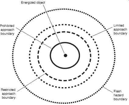
FIG. 35 Minimum approach distance definitions.
Energized object; Prohibited approach boundary; Restricted approach boundary; Limited approach boundary; Flash hazard boundary
=======
Qualified Persons. Qualified personnel approach distances are determined from columns (4) and (5) of Table 15. No one may cross the restricted or the prohibited approach boundaries without meeting the requirements, which are defined later in this section. Note that the minimum requirements for crossing either of these boundaries include:
1. The worker must be qualified and fully trained for the work and the hazards that will be encountered inside the boundary.
2. The worker must wear all appropriate personnel protective clothing and use all required safety procedures and tools such as insulated hand tools inside the restricted approach boundary.
Specific Requirements for Crossing the Restricted Approach Boundary. To cross the restricted approach boundary, the following criteria must be met:
• The worker must be qualified to do the work.
• There must be a plan in place that is documented and approved by the employer.
• The worker must be certain that no part of the body crosses the prohibited approach boundary.
• The worker must work to minimize the risk that may be caused by inadvertent movement by keeping as much of the body out of the restricted space as possible. Allow only protected body parts to enter the restricted space as necessary to complete the work.
• Personal protective equipment must be used appropriate for the hazards of the exposed energized conductor.
TABLE 15 approach Boundaries to Live Parts for Shock Protection
Specific Requirements for Crossing the Prohibited Approach Boundary. NFPA 70E considers crossing the prohibited approach boundary to be the same as working on or contacting an energized conductor. To cross into the prohibited space, the following requirements must be met:
• the worker must have specified training required to work on energized conductors or circuit parts.
• there must be a plan in place that is documented and approved by the employer.
• a complete risk analysis must be performed.
• authorized management must review and approve the plan and the risk analysis.
• personal protective equipment appropriate for the hazards of the exposed energized conductor must be used.
TABLE 16 Human Tissue Tolerance to heat, second- Degree Burn
Calculating the Flash Hazard Minimum Approach Distance (Flash Protection Boundary)
TABLE 17 Methods for calculating Flash Boundary Approach Distances below 600 V
Introduction. The concept of a minimum approach boundary for flash protection is based on the amount of tolerance that human tissue has to heat. The current industry standards use the so-called Stoll Curve developed by Stoll and Chianta in the 1960s. The flash boundary then represents the closest distance that an unprotected (meaning not wearing thermal protective clothing beyond normal cotton garments) worker may approach an electrical arcing source. Theoretically, at the flash boundary distance, if the worst-case electrical arc occurs, the unprotected worker has a 50 percent chance of a just-curable burn-that is, a second degree burn. Table 16 is a reproduction of the Stoll Curve table.
Low-Voltage Calculations (Below 600 V). Table 17 lists five methods that may be used for calculating the minimum approach distances for electrical flash when the circuit voltage is below 600 V.
Note that methods 3 and 4 in Table 17 are actually solutions to the Doughty, neal, and Floyd equations for incident energy = 1.2 cal/cm2. This means that methods 3 and 4 must be used only within the constraints under which the empirical equations were developed-circuits with fault currents between 16 and 50 ka, 600 V or less, 18 in or more from the arc source. The "arc- in- a- box" method is based on a test method using a box 20 in on a side.
If we assume a 480 V circuit with a maximum fault current of 20,000 a and a tripping time of 0.1 s, the four methods generate the following results:
Method 1: 4 ft Method 2: 2.1 ft (top formula only) Method 3: 2.19 ft Method 4: 3.44 ft Method 5: 2.28 ft
The NFPA method 2; the Doughty, Neal, and Floyd equations for open-air arcs (3); and method 5, the IEEE calculator, agree very closely. Method 4 gives a larger flash boundary, since the "arc- in- a- box" method assumes that the energy is focused toward the worker. That is, most of the energy goes in one direction.
Method 5 employs the IEEE flash hazard calculator provided with the IEEE Std 1584 2002. This calculator is a Microsoft Excel spreadsheet application that calculates both incident energy and flash boundary. It is a relatively "easy to use" application; however, as with all of the calculation methods given in this section, it should be employed only by qualified, experienced engineers with sufficient background and experience to use the tool correctly.
Medium- and High-Voltage Calculations. Much of the research that has been done on flash boundary calculations has concentrated on the low- voltage spectrum (600 V and less); consequently, the availability of empirical support applied to medium- and high-voltage systems for the various derived formulas is sparse.
Method 5 is the best choice for calculating the flash boundaries for medium-voltage systems up to 15 kV. However, in the absence of the IEEE standard, the engineer may use method 2 with certain cautions.
Calculating medium- and high- voltage flash boundaries using method 2 ( Table 17)
Appears to give conservatively high results when compared to software programs derived using industry-standard heat transfer calculations.
To calculate the flash boundary for medium- voltage systems, use the top formula given in method 2. Then enter the result into one of the commercially available (or freeware) soft ware programs and verify that the received heat flux density is on the order of 1.2 cal/cm2.
CALCULATING THE REQUIRED LEVEL OF ARC PROTECTION (FLASH HAZARD CALCULATIONS)
Note: The formulas and methods used in the following sections are based on the most cur rent information available at the time of this writing (July 2011).
Ongoing research is being performed in an attempt to improve these formulas and methods. Always refer to the latest editions of NFPA 70E and IEEE Standard 1584 for the most current information.
Introduction
Flash protection beyond normal cotton or wool work clothing is not required as long as all parts of the worker's body stay outside the flash boundary as calculated above. Outside the flash boundary, the minimum recommendation is either:
1. Flame-resistant clothing with an ATPV of 4.5 cal/cm^2 or higher
2. Natural fabric (cotton or wool) work clothing of 7 oz/yd2 or more remember that these are minimum recommendations. Many organizations (including the author's company) require their electrical personnel to wear 8 cal/cm^2 at all times when in the field.
If, however, the worker must cross the flash boundary and is qualified to do so, he or she must wear flame-resistant clothing to protect against the arc incident energy levels that may be encountered.
To provide arc protection, the worker must select and wear flame-resistant clothing with an ATPV or EBT equal to or greater than the incident energy level. Note that the incident energy level is calculated based on a given distance between the arc source and the worker, for example 24 in. The worker will not be adequately protected if he or she gets any closer than the distance used in the calculation for the specific situation. Flash boundaries can be calculated from the formulas in this section by setting the incident energy level to 1.2 cal/cm^2 (5.02 J/cm^2) and then solving the appropriate equation for the distance.
Caution: The following sections present several complex calculation procedures using a variety of mathematical and engineering applications. These calculations should be per formed or evaluated only by qualified, experienced engineers or other technical personnel with the requisite knowledge and skills. The Lee Method
This method is named after its developer, Ralph Lee, P.E. (deceased). Lee was one of the early and most successful researchers into the theoretical models for the amount of energy created by an electrical arc and the amount of incident energy received by workers in the vicinity of the arc.
The Lee method is a theoretical model and is based on two major assumptions:
1. The maximum energy transfer from the power system to an electric arc is equal to one half of the bolted short-circuit power available at the point where the arc occurs.
2. All of the arc electrical energy will be converted to the incident heat energy.
Starting with these two assumptions, Lee and subsequent researchers have refined the Lee method to the form shown in Eq. 4 (4.4) where
E = incident energy (J/cm2 or cal/cm2 depending on the value of K)
K = a constant; if K = 2.142 then E is in J/cm2 ; if K = 0.512 then E is in cal/cm2
V = system phase-to-phase voltage (kV)
Ibf = bolted fault current (ka)
t = arcing time (seconds)
D = distance from the arcing point to the worker (mm)
The Lee method is a very conservative method and was developed without the aid of the empirical results available today from the extensive research in this field. While it can be used for all situations, its principal application is in those cases that have not been modeled based on actual experimental measurements. It is most often used in systems where the system voltage is greater than 600 V and/or where fault currents, arc lengths, or other such parameters are beyond the ranges that have been tested using field measurements.
Although the Lee method does not take the focusing effect of equipment into account, the so-called arc-in-a-box, it is nonetheless very conservative. The use of multipliers should be required only in the most extreme applications.
Note: all of the NFPA and IEEE methods described in the following sections are based on empirical field testing using a configuration similar to what is shown in FIG. 36. A manikin outfitted with heat sensors is placed inside a faraday cage. Electrical terminals are placed in proximity to the manikin and an arc is started. The heat energy is captured on instruments.
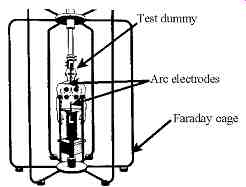
FIG. 36 Electrical arc test setup used to determine arc Thermal Performance
Value (aTPV).
Multiple experiments are performed using different distances and arc times. The resulting data is mathematically manipulated into a curve fit. The resulting equations (such as Eq. 5) are then used to calculate arc energies at various distances.
Methods Outlined in NFPA 70E
In addition to the Lee method, NFPA 70E, Standard for Electrical Safety in the Workplace, gives two different methods for calculating incident energy levels: the method based on empirical formulas developed by Doughty, Neal, and Floyd and the method developed by the IEEE research in the development of IEEE Standard 1584.
Both of these methods rely on curve-fitting data collected using a system similar to the one shown in fig. 30 (Section 3). The manikin has sensors embedded in it, primarily in the chest region. When the arc is initiated, the sensors capture the amount of energy released.
Multiple runs are made and the data from the runs is curve-fitted to create the empirical formulas included in this section.
Method #1. This method is based on a research by Richard L. Doughty, Thomas e. Neal, and H. Landis Floyd.
They performed research using the thermal manikin approach described in Section 1. Their research was bounded by the following conditions:
1. Systems with voltage levels of 600 V and below
2. Systems with maximum available short-circuit currents between 16 ka and 50 ka
3. Working distances of equal to or greater than 18 in after running numerous tests by creating electric arcs in open air, they took their results and performed a curve fit to predict the incident energy. Equation 5 is the formula that was developed and that most closely models the energies they measured.
…where EMA = maximum open-air arc incident energy (cal/cm^2)
DA = distance from the electrodes (in)-note that DA = 18 in
tA = duration of the arc (seconds)
ISC = short-circuit current (ka)-note that ISC is the actual arc current, not the maximum bolted fault current
In the second part of their research, they created electrical arcs in a cubic box with one open side. The box was 20 in on a side and the measurements were taken at various distances from the open end. They then performed a curve fit to model the results. Equation 4.6 is the resulting formula.
where EMB = maximum arc-in-a-box incident energy (cal/cm2)
DB = distance from the electrodes (in)-note that DB = 18 in all other variables are as described for the open-air formula (Eq. 5).
Using either Eq. 5 or 6, incident energies can be calculated, then protective clothing can be purchased with the necessary ratings.
Method #2. This method is actually the method taken from the IEEE Standard 1584 2002. This method is described in the next section.
=======
TABLE 18 System Limits for Calculation of Incident
Energy using IEEE Standard 1584-2002 System phase-to-phase voltage 0.208 to 15 kV System frequency 50 to 60 hz Short-circuit current range 700 to 106 ka Conductor gap (arc length) 13 to 152 mm
=======
IEEE Std 1584-2002
System Model Limitations. Institute of Electrical and Electronics Engineers (IEEE) working group P1584 has performed research and theory development over several years to expand the work done by Doughty, et al.
…as shown in Table 18, the working group has significantly expanded the applicable range for the application of their methods.
Calculation of Arcing Current. One of the principal drawbacks of the Lee method is that the bolted fault current, which is used in that method, is always somewhat greater than the actual current flow when an electrical arc is formed. At voltages below 1000 V, the arcing current is often substantially less than the bolted fault current. (as mentioned in Section 2, the Lee method also assumes maximum power transfer, which is not usually the case in actual applications.) Using both theoretical and empirical data, Standard 1584 develops a formula to calculate the arcing current that will be present in a system when the bolted fault current is known. Equations 4.7 and 4.8 are used to calculate the logarithm to the base 10 of arcing current (log10Ia). Equation 4.7 is used for systems below 1 kV, and Eq. 8 is used for systems that are equal to or greater than 1 kV.
...where Ia = arcing current (ka)
K = a constant; K = -0.153 for open-air arcs and K = -0.097 for arc-in-a-box
Ibf = maximum, symmetrical rms, three-phase bolted short circuit current (ka)
V = system three-phase voltage (kV)
G = conductor gap (arc length) (mm) after log10Ia has been calculated from Eq. 7 or 4.8, Eq. 9 is used to calculate Ia.
Calculating Incident Energy. The calculation of actual incident energy is done in two steps using the empirically derived arc current (Ia). In step one, normalized incident energy (En) is calculated. En is normalized for an arcing time of 0.2 second and a distance from the arc of 610 mm. Equations 4.10 and 4.11 are used for this calculation.
TABLE 19 Distance Factors (X) used in Eq. 12
The actual incident energy at any distance D is then calculated using Eq. 12.
...where E = incident arc energy at distance D in cal/cm^2
(kCJ = 1) or J/cm^2
(kCJ = 4.184)
kCJ = 1 for En is cal/cm^2
...and 4.184 for En in J/cm^2
Cf = 1 for systems above 1 kV or 1.5 for systems equal to or less than 1 kV
En = normalized incident energy calculated from Eq. 11
t = arcing time in seconds
D = distance from the arc (mm)
X = a distance exponent taken from Table 19 In Eq. 12, the arcing time (t) will be determined by how long the protective devices require to completely interrupt the short circuit. If the arcing current decreases, the arcing time will generally increase. Because of this, NFPA 70E suggests recalculating Eqs. 7 through 12 using 0.85 Ia and the resulting arcing time. The standard then suggests using the larger incident energy from the two calculations.
Software Solutions
Several software products on the market allow the calculation of incident energy and/or flash boundaries. For example, IEEE Standard 1584-2002 comes with a complete set of Microsoft Excel spreadsheet applications. Users need only enter the values for their particular system to determine the incident energy and the flash boundary using the IEEE method.
Also, virtually all of the commercially available engineering software packages, such as SKM Systems analysis, Inc.-PowerTools for Windows and ESa, Inc. EasyPower, have added arc-flash calculation packages to their short-circuit analysis and coordination study packages.
Required PPE for Crossing the Flash Hazard Boundary
To select the level of flame- resistant protection required, the following procedure may be used:
1. Calculate the incident arc energy value as shown previously.
2. Select clothing that provides an aTPV* or EBT
...that is less than the incident energy value previously calculated. Double layers of protective clothing may be required at the higher energy levels. Refer to the manufacturers for recommendations.
Caution: Current regulatory standards strongly suggest that locations with incident energy in excess of 40 cal/cm^2 should be evaluated very closely. Generally, workers should not be required to work in areas where the arc energy exceeds 40 cal/cm^2.
TABLE 20 hazard risk Category Classifications
TABLE 21 Protective Clothing and Personal Protective Equipment (PPE) Matrix
TABLE 22 Protective Clothing Characteristics
A Simplified Approach to the Selection of Protective Clothing
The National fire Protection association provides a simplified approach to the selection of protective clothing. While this method is convenient and economical, it should be used with extreme caution. Many have used this method without paying attention to the boundary conditions set up by the tables.
The method assumes certain short-circuit and operating time values. Users must be absolutely certain that their power system falls within the assumed values.
Note: The tables used in this section are taken from the 2009 edition of NFPA 70E. The user should always refer to the current version of that document to make sure that no changes have occurred.
1. Identify the hazard/risk category from Table 20. Note that this is based on the type of work that will be performed. Note also that Table 20 identifies whether insulating gloves and/or tools are required.
2. Use Table 21 to select the various types of PPE required for the hazard determined in step 1.
3. Use Table 22 to select the weight of flame- resistant clothing required for the task.
Although this procedure is quite simple and straightforward, it should be used carefully for at least two reasons:
• Because it is conservative, it tends to result in substantial amounts of clothing for the employee. Workers may tend to disregard necessary equipment out of frustration.
• The standard is task based rather than location based. Using the quantitative methods described previously will provide, ultimately, a more easily applied set of rules.
• In some rare cases, the simplified approach may give values that do not provide adequate protection. This is especially critical if the limits imposed by the method are ignored.
• This method is dependent on the boundary conditions given at the bottom of Tables 4.20 and 4.21. If the location does not comply with these footnotes, this method should not be used.
BARRIERS AND WARNING SIGNS
Barriers and warning signs should be placed to control entrance into a work area where there are exposed energized conductors. The installation of such equipment will vary depending on the layout of the work area. The following general criteria should be applied:
• The signs should be distinctive, easy to read, and posted at all entrances to the work area.
The signs should clearly warn personnel of the hazardous or energized condition.
• Barriers and barrier tape should be placed at a height that is easy to see. Three feet or so is a good starting point. Adjust the height as dictated by the specific installation.
• Barriers and barrier tape should be placed so that equipment is not reachable from outside of the barrier. This will prevent the accidental or intentional operation of equipment by unauthorized personnel.
• If sufficient work room is not available when barriers are placed, attendants should be used to warn employees of the exposed hazards.
FIG. 37a shows a sample arrangement for a work area in a switchgear room. The layout given here is for example only; however, the general principles may be used. Key points for this installation are
1. Stanchions are used to provide a firm structure for stringing the barrier tape.
2. Warning signs are placed at both entrances warning personnel that hazards exist inside.
3. Warning signs are also posted on the switchgear itself.
4. five to ten feet of work clearance is allowed between the tape and the switch gear. This number may vary depending on the space available and the work to be performed.
FIG. 37b shows a similar barrier system for a hallway lighting panel. The clearance distance here is less because of the need to allow passage down the hallway. Warning signs are used to alert personnel to the hazard.
Illumination
Personnel must not reach into or work in areas that do not have adequate illumination. This statement makes it mandatory to set up temporary lighting for many jobs. In areas where lighting is poor, the installation of additional permanent lighting fixtures is the indicated correct remedy. Although de-energization is the preferred method of eliminating electrical hazards, if de-energization also eliminates illumination, alternative safety measures must be employed.
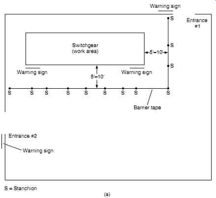
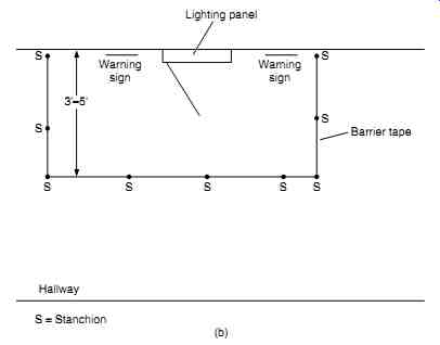
FIG. 37 (a) Barriers and warning signs around a work area in a switchgear
room with two entrances. (b) Barriers and warning signs around a lighting
panel that is open for work.
Conductive Clothing and Materials
When working on or around energized conductors, personnel should remove watches, rings, keys, knives, necklaces, and other such conductive items they have on their bodies because (1) they conduct electricity and could possibly cause an arcing fault, and (2) in the event of an arcing fault, they conduct heat.
Conductive materials such as wire, tools, and ladders should be handled in such a way that they do not come into contact with energized conductors. If such material cannot be kept at a safe clearance distance (see "Approach Distances" section), they should be wrapped or insulated. Metal ladders should never be used in electrical installations.
Confined Work Spaces
A complete coverage of confined work spaces is beyond the scope of this guide.
Always refer to the current version of 29Cfr1910.146. Electrical safety hazards in con fined work spaces should be avoided. The following steps should be employed:
1. If safe approach distances cannot be maintained, energized conductors should be covered or barricaded so personnel cannot contact them.
2. Doors, hatches, and swinging panels should be secured so that they cannot swing open and push personnel into energized conductors.
3. Confined work spaces should be well ventilated to prevent the concentration of gases that may explode in the presence of an electric arc.
4. Exits should be clearly marked. Employees should be familiarized with the exits before entering the confined work space.
5. Confined work spaces must be well illuminated so that all hazards are clearly visible.
TOOLS AND TEST EQUIPMENT
General
Many electrical accidents involve failures of electric tools or test equipment. Such failures take a number of different forms including insulation failure, open ground return wires, internal shorts to ground, and overheating. These problems can be aggravated or even caused by using tools or test equipment improperly. For example, if extension cords not designed for use in wet areas are used in standing water, severe electric shock can result. The following general procedures should be employed when using electric tools or test equipment:
1. Tools and test equipment should be closely inspected before each use. (See the "Visual Inspections" section.)
2. Cord-connected tools should never be lifted or handled by their power cord. If tools must be lifted, a rope should be attached.
3. Grounded tools and equipment must have a continuous metallic connection from the tool ground to the supply ground.
4. If a grounded supply system is not available, double-insulated tools should be used.
5. Three-wire connection plugs should never be altered to fit into two-wire sockets.
6. So-called cheater plugs should not be used unless the third wire of the plug can be securely connected to the supply ground.
7. Locking types of plugs should be securely locked before the tool is energized.
8. Cords and tools should not be used in a wet environment unless they are specifically designed for such an application.
Authorized Users
Only authorized, trained persons should be allowed to use electric tools and test equipment.
Training should include all the necessary inspection techniques for the tools that will be employed, plus recognition of the common types of safety hazards that are specific to the tool being used.
Visual Inspections
Tools and test equipment should be closely inspected before each use. This inspection should occur at the beginning of each work shift and again any time a problem is suspected.
The inspector should look for the following types of problems:
• Missing, corroded, or damaged prongs on connecting plugs
• Frayed, worn, or missing insulation on connecting cords and/or test leads
• Improperly exposed conductors
• Bent or damaged prongs or test probes
• Excessive exposure on test prongs
• Loose screws or other poorly made electrical connections
• Missing or mis-sized fuses
• Damaged or cracked cases
• Indication of burning, arcing, or overheating of any type If any of these problems are noted, the tool or test equipment should be removed from service until the problem can be repaired. If repair is not feasible, the tool or test equipment should be replaced.
Electrical Tests
Tools and extension cords should be electrically tested on a monthly basis. The following tests should be performed:
1. Ground continuity test. A high current (25 a minimum) should be applied to the tool's ground circuit. The voltage drop on the ground circuit should be no more than 2.5 V.
2. Leakage test. This test determines how much current would flow through the operator in the event that the tool's ground circuit were severed.
3. Insulation breakdown. This test applies a high voltage (up to 3000 V) to the tool's insulation system and then measures the amount of leakage current.
4. Operational test. This test applies rated voltage to the tool and determines how much current the tool draws.
If the tool fails any of the above tests, it should be removed from service until it can be repaired. If repair is not possible, the tool or cord should be replaced. FIG. 38 is a test set designed especially to check the power circuits for cord-connected tools and extension cords.
Wet and Hazardous Environments
Tools and test equipment should be used only in the environments for which they have been designed. If the work area is wet, only tools that are rated for wet work should be used.
Fully insulated, waterproof cords should be used if they will be exposed to water or conductive liquids.
If work must be performed in explosive environments, the tools used should be sealed or otherwise designed so that electric arcs will not ignite the explosive materials.
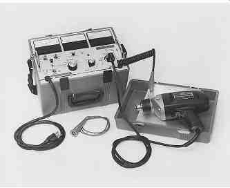
FIG. 38 Tool and appliance tester. (Courtesy AVO International.)
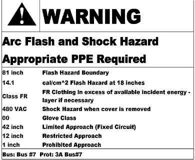
FIG. 39 Typical warning label to be posted on electrical equipment.
(Label generated by SKM Power Systems Analysis Inc., PowerTools for Windows
Software.)
FIELD MARKING OF POTENTIAL HAZARDS
The type and degree of hazard determined by the various procedures outlined in this section should be clearly posted at each piece of electrical equipment in the field. These warning labels should clearly identify the type and degree of the hazard and should include the type and amount of PPE required to work in, on, or around the equipment. FIG. 39 is an example of such a label.
Warning labels of this type should be placed on switchboards, panelboards, industrial- control panels, metal-clad switchgear, meter-socket enclosures, motor-control centers, transformers, motors, generators, and all other such equipment where employees may be exposed to one of the electrical hazards.
Some equipment may have more than one such label. For example, the primary of a transformer may have a different arc-energy level than the secondary. Depending on the mechanical configuration, a label may be required for the primary feeder section of the transformer and the secondary transition cabinet into the switchgear that it feeds.
------
1. Notify responsible personnel of your presence in the area.
2. Listen for any abnormally loud or unusual noises. Sniff for unusual odors.
3. Locate all emergency exits.
4. Locate all fire alarms and telephones.
5. Inspect all transformer liquid level, temperature, and pressure gauges to make certain that they are within acceptable limits.
6. Locate the station one-line diagram and make certain that it is legible and correct.
7. Make certain that the room is neat and tidy. Generally, electrical facilities should not be used for the storage of equipment.
8. Be certain that all required safety equipment is readily available and easily reached.
9. Check to see that all protective relay and other operational flags are properly reset.
TABLE 23 The one-Minute Safety audit
------
THE ONE-MINUTE SAFETY AUDIT
Inattention is one of the major root causes of all accidents. Employees whose attention is distracted by work-related or personal problems are prone to miss obvious signs of impending hazards. To make certain that employees are constantly aware of potential hazards, the steps listed in Table 23 should be performed by each worker who enters an area where any of the electrical hazards may be present.
The following nine simple steps are explanations of each of the items in Table 23.
Together they should not take more than a minute or two to perform, even in a very large electrical facility. Of course, not every step will apply in each and every situation. For example, some electrical rooms have no transformers; therefore, step 5 would not be per formed.
1. Notify responsible personnel of your presence in the area. In the event that a problem does occur, you may not be able to summon the help that you need. If other personnel are aware of your presence in the area, they will know to come to your aid.
2. Listen for any abnormally loud or unusual noises. Sniff for unusual odors. Transformers and other electric equipment do make noise during normal operation. When such noises become too loud or change tone, trouble may be indicated. Burning odors or the smell of ozone can also be signs of incipient faults.
3. Locate all emergency exits. Electrical accidents are often accompanied by smoke, fire, and noise. Such conditions make it difficult or impossible to find the exits. If exit locations are committed to memory before any problems occur, the worker is more likely to remember them after the problem occurs.
4. Locate all fire alarms and telephones. The same reasoning applies here as locating emergency exits. During an emergency, the location of fire alarms and telephones should be a reflex.
5. Inspect all transformer gauges. Transformers will often warn of impending failures by an increase in pressure, temperature, liquid level, or some combination of all these. An inspection of these elements can warn of a problem before it happens.
6. Locate the station one-line diagram. Switching and other such activities must be carried out in a safe manner. To do so requires that the system one-line diagram be accurate. Few things are more hazardous than opening a switch that is believed to be the source to an energized part of the system and then finding out later that, in fact, it was the wrong switch.
7. Make certain that the room is clean and tidy. Storage of some equipment in an electrical facility is a necessary and valuable procedure. For example, what better place to store electrical safety equipment than close to the gear where it may be needed. Ladders, tools, hot sticks, rubber insulating goods, replacement lights, and other such materials are all candidates for storage in the electrical facility. When such storage does take place, how ever, it should be done in an orderly and safe fashion. Storage cabinets should be pro cured for small equipment. Ladders should be hung on racks especially mounted for such a purpose. Wire reels and other such materials should not be in the exit paths.
8. Be certain that all safety equipment is readily available. Workers will often use the excuse that "the safety gear is too far away to justify using it for this short procedure." To eliminate such an excuse, the safety equipment should be readily available. Whether it is brought in with the work crew or stored in the electrical facility, it must be readily available.
9. Check all protective relay flags and other indicators. Operation indicators can often be a precursor of a safety problem. A pressure alarm that will not reset, for example, can indicate an impending explosion. Such indicators should be checked. Such an indicator should never be reset without first determining what caused the problem.
Also, operations personnel should be contacted before resetting.
These nine simple steps can be quickly accomplished by all personnel . . . and they may save a life.
Also see: Electrical safety systems
| Top of Page | PREV. | NEXT | Index |