AMAZON multi-meters discounts AMAZON oscilloscope discounts
Isolation Verification
After the locks and tags have been applied, the following steps should be employed to verify that the de-energization was successful:
1. Make certain that all employees are clear of the de-energized conductors.
2. Attempt to reenergize the system by operating the circuit breaker control handles, pushing the switch to close it, or whatever other procedure is appropriate.
3. Using proper procedures and test equipment, measure the voltage on conductors at the point(s) where employee exposure will take place. The voltage must be zero.
Removal of Locks and Tags
Normal Removal. When the work is finished and an employee is ready to remove his or her locks and tags, the following general approaches should be used:
• The work area should be inspected to ensure that nonessential items have been removed and all components are operationally intact.
• The work area should be inspected to ensure that all employees have been safely removed or positioned.
• remove any specialized equipment such as safety grounds or spring tension blocks.
• Notify all affected employees that locks and tags are to be removed.
• Locks and tags should be removed by the personnel that placed them.
Control Bypass. If the employee who placed the locks and tags is absent and not available to remove them, and if the locks and tags absolutely must be removed, another authorized employee should assume control of the equipment and remove the absent employee's locks and tags. The following steps must be employed:
1. The employee who is assuming control must make an assessment of the situation and determine that a genuine, critical need exists to remove the absent employee's locks and tags. Examples of such critical needs include:
a. Immediate operation and/or production requires the equipment to resume operation and avoid general shutdown.
b. Personnel safety requires restoration of power to the de-energized systems.
c. Equipment must be temporarily returned to service to allow testing or other such evaluation.
2. The employee assuming control must make every reasonable attempt to contact the absent employee to obtain his or her assessment of the equipment.
3. The employee assuming control must contact other employees who may have knowledge of the availability of the equipment and the advisability of removing the absent employee's locks and tags.
4. The employee assuming control must develop and document a formal conclusion with regard to the decision to remove the absent employee's locks and tags.
5. If the employee assuming control intends to apply his or her own locks and tags, he or she should do this, following all of the steps normally used for lockout-tagout-including voltage measurement.
6. The employee assuming control must follow the normal removal steps to remove the locks and tags and either reinstall his or her own locks and tags or reenergize the system.
7. The area where the absent employee's locks and tags were removed should be posted with large, easy-to-read signs indicating that the locks and tags have been removed.
8. The employee assuming control must contact the absent employee immediately upon his or her return. The returning employee must be told that his or her locks and tags have been removed and completely updated as to the status of the equipment. The absent employees shall remove the signs posted in step 7.
FIG. 26 shows a form that may be used to document the control bypass procedure.
In this figure the employee who is assuming control is referred to as the authorized controller. The absent employee is referred to as the authorized employee. Notice that each one of the major steps is documented on this form.
Temporary Removal. Locks and tags may be temporarily removed by the employee who placed them. When doing so, the same steps used in normal removal should be observed.
Safety Ground Application
Safety grounds should be applied as an additional safety measure when equipment is removed from service. The only exception to this is when the nature of the work precludes the use of safety grounds. Procedures like insulation measurement cannot be performed when safety grounds are applied; therefore, they may not be used, or must be temporarily disconnected for the measurement process.
Control Transfer
Lockout-tagout control may be transferred from one employee to another as long as both employees are present. The following steps should be used:
1. The employee assuming control first applies his or her locks and tags using all of the steps described elsewhere in this guide.
2. The employee relinquishing control then removes all of his or her locks and tags.
All logs or other such records should be immediately updated to show the new lockout tagout condition.
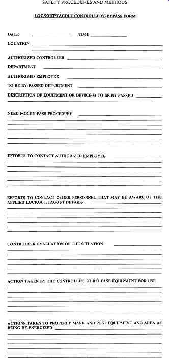
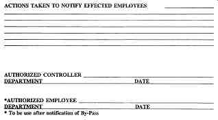
FIG. 26 Lockout-tagout control bypass form.
Nonemployees and Contractors
Nonemployees such as contractors should be required to use a lockout-tagout program that provides the same or greater protection as that afforded by the facility's procedure.
Contractors should be required to submit their procedure for review and approval. No work should be allowed until the contractor's lockout-tagout program has been reviewed and approved by qualified management.
If the contractor's lockout-tagout program is more stringent than the owner's pro gram, the contractor's program should be utilized. If the contractor's program is not as stringent as the owner's program, the contractor must be trained in and required to use the owner's lockout-tagout program. OSHA requires a meeting of the minds in this situation.
If contractors are allowed to use their lockout-tagout procedures, all employees should be familiarized with the contractors' procedure and required to comply with it.
Copies of the respective standards should be made available for both contractors and employees. Likewise, all contractors must be familiar with the facility's procedure and must comply with it.
If the contractor is working on machines or equipment that have not yet been turned over to the facility, the contractor shall be required to lock and tag that equipment if it might operate and endanger employees. The contractor must guarantee the safety of the locked and tagged installation. As an alternative to this procedure, the contractor should be required to allow gang lockout and tagout with employees and contractor personnel.
Lockout-Tagout Training
All employees should be trained in the use, application, and removal of locks and tags. See Section 14 for more information on general employee safety training.
Procedural Reviews
The entire lockout-tagout procedure should be reviewed at intervals no longer than one year. A review report should be issued that identifies the portions of the procedure that were reviewed, changes that were considered, and changes that were implemented.
VOLTAGE-MEASUREMENT TECHNIQUES
Purpose
No circuit should ever be presumed dead until it has been measured using reliable, pre checked test equipment. Good safety practice and current regulatory standards require that circuits be certified de-energized by measurement as the last definitive step in the lockout tagout procedure.
Instrument Selection
Voltage-measuring instruments should be selected for the category, voltage level, the application location, short-circuit capacity, sensitivity requirements, and the circuit loading requirements of the circuit that is to be measured.
During voltage measurement, the instrument may be subjected to voltage transients.
This is especially critical in low-voltage (below 1000 V) applications. When selecting a low-voltage-measuring instrument, be certain to select the correct category of instrument as defined in IEC 61010. See Section 3 for a description of the categories.
Voltage Level. The instrument must be capable of withstanding the voltage of the circuit that is to be measured. Use of underrated instruments, even though the circuit is dead, is a violation of good safety practice.
Application Location. Some instruments are designed for outdoor use only and should not be used in metal-clad switchgear. Always check the manufacturer's information and verify that the instrument is designed for the location in which it is being used.
Internal Short-Circuit Protection. Industrial-grade, safety-rated voltage-measuring instruments are equipped with internal fusing and/or high-resistance elements that will limit the short-circuit current in the event the instrument fails internally. Be certain the instrument being used has internal protection with an interrupting/limiting rating that is at least equal to the short-circuit capacity of the circuit that is being measured. Also, if a fuse must be replaced, always replace it with the exact type used by the manufacturer or with a different one that is approved by the manufacturer.
Sensitivity Requirements. The instrument must be capable of measuring the lowest normal voltage that might be present in the circuit that is being measured. If the instrument has two ranges (high and low, for example), be certain to set it on the correct lowest range that applies to the voltage being measured.
Circuit Loading. A real voltmeter can be represented by an ideal meter in parallel with a resistance. The resistance represents the amount of loading the meter places on the circuit ( FIG. 27). In the diagram, RS represents that resistance of the system being measured and RM is the internal resistance of the voltmeter. The voltmeter will read a voltage given by the formula:
V = V x [ R / (R + R)]
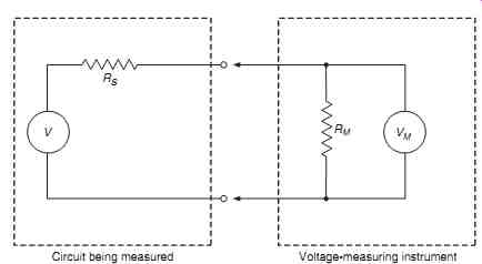
FIG. 27 Equivalent circuit of voltage measurement. Circuit being measured;
Voltage-measuring instrument.
If the meter internal resistance is very high compared to system resistance, the voltage across the meter will be close to the actual system voltage. If the meter resistance is very low compared to the system resistance, the meter will read a lower voltage than actually exists because most of the voltage drop will be across the system resistance instead of the meter resistance. In this second situation, the meter is "loading" the circuit.
If a very low-resistance meter is used, the meter may not read a potentially lethal static or inductively coupled voltage. This situation is unacceptable since an inductively coupled or static voltage can be lethal. The meter that is selected for a safety-related voltage measurement must have an internal resistance that is high enough to avoid this problem.
Instrument Condition
Before each use, an instrument must be closely inspected to ensure it is in proper working order and that insulation systems have not been damaged. The case physical condition, probe exposure, lead insulation, fusing, and the operability of the instrument should be verified.
Case Physical Condition. The case must be free of breaks, cracks, or other damage that could create a safety hazard or misoperation. Broken instruments should be taken out of service until they can be repaired or replaced.
Probe Exposure. Modern instrument probes have sleeves that cover all of the probe except the tip. The older spring-loaded sleeve types are no longer allowed. Check to make certain that only the minimum amount of probe required to do the job is exposed.
Lead Insulation Quality. Carefully inspect the lead insulation to make certain it is not damaged in any way.
Fusing. Accessible fuses should be checked to be certain that they are correctly installed and have not been replaced by incorrect units.
Operability. Before each usage (at the beginning of each shift, for example), the instrument should be checked to make certain that it is operable. Do not substitute this check for the instrument checks required in the three-step process.
Three-Step Measurement Process
Step 1-Test the Instrument. Immediately before each measurement, the instrument should be checked on a source that is known to be energized. This step confirms that the instrument is working before the actual circuit verification is made.
The preferred method is to use an actual power system conductor of the same voltage as that being verified. Finding such a circuit is easier when low-voltage measurements are being made; however, even then an energized circuit may not be available. Some manufacturers supply a device that creates a voltage that is sufficient for testing the instrument.
Some instruments intended for measurement of medium voltages have a low-voltage switch setting on them that allows them to be checked on low voltage. This is not a preferred method since a problem with the switch could give erroneous, dangerously false readings.
Step 2-Measure the Circuit Being Verified. After the instrument is tested, the worker then measures the circuit being verified to make certain it is de-energized. The actual wires that should be measured and the techniques to be used are discussed later in this section.
Step 3-Retest the Instrument. After the circuit has been verified, the instrument should be rechecked as it was in step 1. This ensures that the instrument was operable both before and after the measurement, thus affirming that a zero measurement is zero and not caused by an inoperable instrument.
What to Measure
As a general rule of thumb, all normally energized conductors should be measured to ground and to each other. The readings to ground should be made whether the system is grounded or not. Note that all readings should be made as close to the point of exposure as possible.
The procedures given in the following paragraphs will apply only to contact-type instruments. Proximity instruments measure the electrostatic field set up around an energized conductor rather than the actual voltage between two conductors. If the proximity indicator shows an unexpected voltage, the circuit should be rechecked, possibly with a contact tester.
Single-Phase Systems. The hot wire of single-phase systems should be measured both against neutral and ground. FIG. 28 shows the points that should be measured. The voltage between neutral and ground should also be checked.
Two-Phase Systems. A voltage measurement should be taken between the two hot phases, between each hot phase and neutral (one at a time), and between each hot phase and ground. If the neutral is remotely grounded, a measurement between neutral and local ground should also be made. FIG. 29 shows the measurement locations for a typical two-phase system.
Three-Phase Systems. Measure between each of the hot wires, two at a time, between each hot wire and neutral, and between each hot wire and ground. If neutral is remotely grounded, a measurement should be made between neutral and local ground. FIG. 30 shows the measurement locations for a typical three-phase system.
Using Voltage Transformer Secondaries for Voltage Measurements. Many medium voltage power systems are equipped with step-down voltage transformers that are used for metering or telemetering purposes. Because of the lower voltage on the secondary, some workers wish to measure the secondary winding voltage to verify that the primaries are de-energized. Such transformers may be used for safety-related voltage measurements under the following conditions:
1. The transformers can be visually traced and are known to be connected to the system where exposure will occur.
2. The transformers are located close to the part of the system where exposure will occur.
3. The transformer secondaries must be measured both before and after the circuit is deenergized. This verifies that the transformer fuses are not blown, resulting in an erroneous zero voltage reading.
4. A safety ground is applied to the primary circuit of the transformer after the measurement but before personnel contact occurs.
5. All other safety-related techniques should be used as described in the other parts of this section.
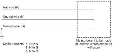
FIG. 28 Measurement points for a single-phase system (one hot wire).
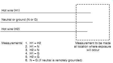
FIG. 29 Measurement points for a two-phase system (two hot wires).
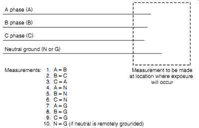
FIG. 30 Measurement points for a three-phase system.
Caution: This procedure is considered a secondary, non-preferred method. Do not use this approach unless absolutely necessary.
Using Panel Voltmeters for Voltage Measurements. Panel voltmeters may be used as a general indication of system energization; however, they should not be used for safety related voltage measurements.
How to Measure
Preparation. Table 11 identifies the steps that should precede the actual measurement procedure. The area should be cleared of unnecessary personnel. This will prevent their exposure to arc or blast in the event that a problem occurs. The person making the measurement should wear and use appropriate safety equipment. (Safety equipment information will be covered later in this section.) After the safety equipment is on, the panels, doors, or other access means should be opened to expose the conductors that are to be measured. The measuring instrument is then carefully positioned. When making medium-voltage measurements with hot sticks, be certain that the hot stick is not contacting your body. The instrument should be securely positioned so that it does not fall to the floor if the leads are inadvertently overextended.
=======
• Clear area of unnecessary personnel.
• Wear appropriate safety equipment.
• Expose conductors to be measured.
• Position measuring instrument.
TABLE 11 Voltage Measurement Preparations
=======
TABLE 12 recommended Minimum Safety Equipment for Making Low Voltage Safety Measurements
• Hard hat-ANSI Z89.1 class e or G (as required by voltage level)
• ANSI Z87.1 electrical safety glasses with side shields
• Flame-resistant work clothing (select using arc-flash calculations)
• Class 00 or higher rubber gloves with leather protectors
• Class 00 or higher rubber sleeves (if the measurement requires proximity to energized conductors)
========
TABLE 13 Recommended Minimum Safety Equipment for Making Medium- and high-Voltage Safety Measurements
• Hard hat-ANSI Z89.1 class e
• ANSI Z87.1 electrical safety glasses with side shields
• Flame-resistant work clothing (select using arc-flash calculations)
• Class 00 or higher rubber gloves with leather protectors (class according to voltage level)
• Class 00 or higher rubber sleeves, if the measurement requires proximity to energized conductors (class according to voltage level)
• When sleeves and gloves are worn simultaneously, the voltage class of each should match.
=========
Safety Equipment. Table 12 lists the minimum recommended safety equipment to be worn when making low-voltage measurements. Table 13 lists equipment for medium voltage measurements. The flash suit is identified as optional for outdoor, open-air measurements. Although many line personnel do not wear flash suits when performing overhead work, the use of these uniforms is strongly recommended.
Measurement. After all preparations are made and the safety equipment is put on, the measuring instrument should be applied to the conductors. If a measurement to ground is being made, one lead should be connected to the ground first and then the phase connection made. When measuring between two hot wires, the order of connection is unimportant. If a contact instrument is being used, each lead should be carefully placed on the appropriate conductor. The meter or readout is then observed to see if the circuit is energized. If a proximity instrument is being used, it should be moved gradually toward the conductor until it indicates or until the conductor is touched.
PLACEMENT OF SAFETY GROUNDS
Safety Grounding Principles
Safety grounds are conductors that are connected to a known earth connection and temporarily applied to de-energized system conductors in a grounded and short-circuited configuration. They are used to provide an equipotential zone of protection for personnel working on or around de-energized conductors and to ensure that an accidental reenergization will not cause injury. Power system components should be considered energized until safety grounds and short circuits are in place. Safety grounds should never be placed until the conductors on which they are to be installed have been measured and verified to be de-energized.
See Section 3 for a detailed description of the design and description of safety grounds.
Caution: Safety grounds must be properly designed and sized for the conductors and short-circuit capacity to which they may be subjected. Refer to Section 3 and/or manufacturer's information for specifics.
In the event that the system is accidentally reenergized, enormous magnetic forces are exerted on the safety ground wires. The forces can cause the grounds to whip violently and cause injury to personnel. To minimize this effect, the safety grounds should be as short as possible, and the conductors should be restrained. Also, the grounds should be installed away from the work area and barricaded to provide safety for unqualified and affected personnel.
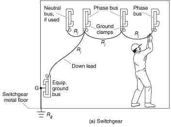
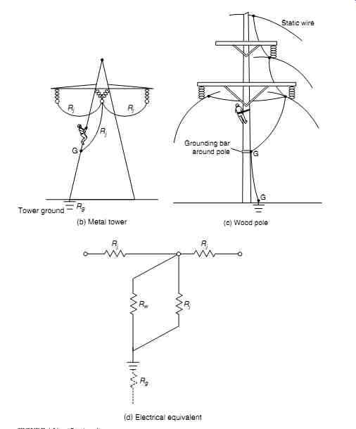
FIG. 31 application of safety grounds to provide a zone of equal potential.
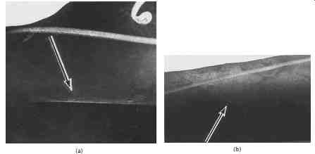
FIG. 32 Two incorrect safety ground configurations.
Safety Grounding Location
Equipotential Grounding. Safety grounds should be applied in such a way that a zone of equal potential is formed in the work area. This equipotential zone is formed when fault current is bypassed around the work area by metallic conductors. FIG. 31 shows the proper location of safety grounds for three different work situations. In each of these situations, the worker is bypassed by the low-resistance metallic conductors of the safety ground.
Assume the worker contacts the center phase in FIG. 31b. With a fault-current capacity of 10,000 a, safety ground resistance (Rj) of 0.001 ohm, and worker resistance (Rw) of 500 ohm, the worker will receive only about 20 ma of current flow.
FIG. 32a through d shows two nonpreferred or incorrect locations for the application of safety grounds. In these diagrams, the worker's body is in parallel with the series combination of the jumper resistance (Rj) and the ground resistance (Rg). The placement of grounds in this fashion greatly increases the voltage drop across the worker's body in the event the circuit is reenergized. Such placements should not be used.
Figures 31 and 32 show ground sets installed on the structures where line workers are performing work. This is for graphic demonstration only. Normally, grounds are installed on both ends of the de-energized, overhead line section being worked on. Personal ground sets are installed on either side of the actual work site no more than two spans away from the work site and within sight of the work site. The only installation on the structure being worked on may be a grounding cluster (a grounding cluster can be seen in FIG. 33) attached to the pole or wooden structure below the work area with a grounding conductor connected to earth (by use of a driven ground rod), a jumper to the system neutral in a wye configuration or a jumper to one of the phase conductors in a delta configuration. All grounding jumpers are installed so the line worker's safety is not jeopardized in the event of a ground set failure or an accidental reenergization of the line through a switching error or contact with a foreign energized line.
Single-Point versus Two-Point Grounding. Single-point grounding is the placement of only one safety ground set. In this procedure, the safety grounds are placed near the point where the work is to be performed, but far enough away so the electrical worker's safety is not jeopardized in the event of a ground set failure or the violent whipping action of the ground set if the circuit is accidentally reenergized with the grounds in place. When possible, the grounds are placed between the worker and the source of electric energy.
Two-point grounding is the placement of two safety ground sets. They are usually placed on opposite sides of the work area; that is, one set is placed "upstream" and one set is placed "downstream" from the workers.
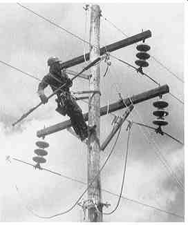
FIG. 33 Worker applying safety grounds. (Courtesy McGraw-Hill, Inc.)
====== TABLE 14 recommended minimum safety equipment for Application of safety Grounds
• Hard hat-ANSI Z89.1 class e
• ANSI Z87.1 electrical safety glasses with side shields
• Flame-resistant work clothing with full head protection (select using arc-flash calculations)
• Class 0 or higher rubber gloves with leather protectors (class according to voltage level)
• Hot stick with suitable fittings for application of safety ground clamps*
*hot sticks may not be usable in cramped switchgear locations. Workers should exercise best safety judgment in such situations.
=========
In general, more safety ground sets are better than fewer; however, the safety ground system must provide a zone of equal potential as described in the previous section.
Application of Safety Grounds Safety Equipment. Table 14 lists the minimum recommended safety equipment that should be worn and used when applying safety grounds. Full shock, arc, and blast protective clothing is required. No matter how carefully the work area is prepared, the possibility still exists for error and/or inadvertent reenergization during the application process.
Notice also that hot sticks are recommended for the actual application process. The use of hot sticks distances the worker from the point of contact and, therefore, minimizes the possibility of injury caused by arc or blast.
Procedure. The actual application procedure will be different for each specific application. The following general steps are recommended.
1. Thoroughly inspect the safety ground set that is to be used. Points to check include
a. Insulation quality
b. Condition of conductors
c. Condition of clamps
d. Condition of ferrule
e. Condition of cable-to-ferrule connection
2. Identify the point at which each ground clamp will be connected to the system. Be certain to select points that minimize the amount of slack in the safety grounds. This will minimize the whipping action in the event the system is reenergized.
3. Put on required safety equipment.
4. Measure the system voltage to make certain that the system to be grounded is de energized. (See the previous sections on voltage measurement.)
5. Make certain that all unnecessary personnel have been cleared from the area.
6. Clean the connection to remove galvanic corrosion with a brush designed for that purpose or use ground clamps with serrated jaws to bite through the corrosion to ensure a low-resistance connection between the conductor and the ground clamp.
7. Apply the ground end of the safety ground sets first. (These points are labeled with the letter "G" in FIG. 31.)
8. Connect the phase-end safety ground clamp to the hot stick.
9. Firmly contact the de-energized conductor with the phase end of the safety ground.
10. Tighten the grounding clamp firmly. Remember that the amount of resistance in the clamp connection can make the difference between a safe connection and a hazardous one.
11. Repeat steps 7 through 9 for each of the phases to be grounded. Note: If using individual jumpers on overhead line construction, attach the second jumper to the conductor already grounded and then to the second phase conductor. For the third jumper, connect the first end to the second grounded conductor and then attach the other end to the third phase conductor. This configuration satisfies the "short-circuited" part of OSHA mandate to install ground sets so as to provide a "short-circuited and grounded" configuration. The short circuiting provides the most rapid clearing time because it causes maximum incident energy to flow instantaneously.
12. Record the placement of each safety ground by identification number. (See "Control of safety Grounds" in the next section.) FIG. 33 shows a worker applying safety grounds to a de-energized system.
The Equipotential Zone
When a proper equipotential zone is established, there will be no lethal potential differences that the worker can reach in the work area. FIG. 31 illustrates configurations that can be used to accomplish this end.
Note, however, that some situations make the establishment of such a zone difficult or impossible. Consider, for example, the employee who must stand on the earth when he or she is working. Since the earth has a relatively high resistivity, the worker's feet will be at a different potential from that of the metallic elements that he must contact.
Two approaches can be used in such circumstances:
1. A metal platform can be laid on the ground and bonded to the grounded metal of the electrical system. FIG. 24 is an example of this approach. In this situation, as long as the worker stays on the metal pad, he or she will remain in an equipotential zone.
2. The worker can be insulated from the earth or other high-resistivity conductors. Rubber mats, gloves, or blankets can be placed so that the worker is completely insulated from electrical contact.
Of course, the best approach is always to establish the equipotential zone; however, these two "work- around" approaches may be used when absolutely necessary.
Removal of Safety Grounds
Safety Equipment. The removal of safety grounds is no less hazardous than applying them. All the safety equipment listed in Table 14 should be worn. Safety grounds should be removed using hot sticks.
Procedure. Safety grounds should be removed as follows:
1. Put on all required safety equipment.
2. Remove each of the phase connections one at a time.
3. Remove the ground connection.
4. Check the ground off as being re moved.
Remember that when safety grounds are not present, the system should be considered to be energized.
Control of Safety Grounds
Safety grounds must be removed before the power system is reenergized. They must also be inspected periodically and before each use. The following sections describe two methods of controlling the safety ground sets.
Inventory Method. Each safety ground set should be identified with its own unique serial number. The serial number should be etched or impressed on a metal tag that is permanently attached to the safety ground set.
A safety officer should be appointed to control the inventory of safety ground sets. This person will control the use of the safety grounds and is responsible for keeping lists of where the grounds are applied during an outage.
As each safety ground set is applied, the safety officer notes its placement on a placement control sheet. As each ground set is removed, the officer notes its removal on the sheet. No reenergization is allowed until the safety officer is satisfied that all safety grounds have been removed. FIG. 34 is a typical safety ground placement control sheet.
The sheet shown in FIG. 34 has the minimum required information. Other columns- such as where the ground set is installed, who installed it, and who removed it-may be added as needed.
Visual Method. Some small facilities may not be able to justify the complexity of a control system such as that described in the previous section. A visual control system may suffice for facilities that have only one or two safety grounding sets. In such a system, a brightly colored rope is permanently attached to each grounding set. Nylon ski rope is ideal for this application. The length of the rope should be determined by the applications; how ever, 3 meters (m) (10 ft) is a good starting point.
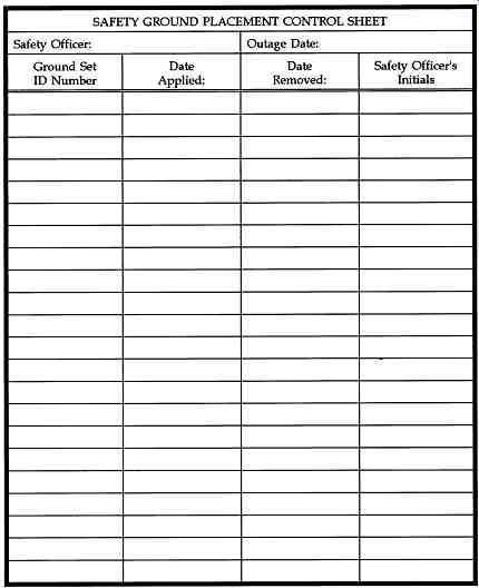
FIG. 34 Safety ground placement control sheet.
At the remote end of the rope, attach a brightly colored warning sign stating "Grounds Are in place" or "This equipment Is Temporarily Grounded." After the safety grounds are attached to the system, the rope should be arranged on the switchgear so that it is easily seen. If it can be arranged, the rope should be placed so the gear cannot be closed up until the rope is removed. The green sign should be placed on the breaker control handle, start push button, or other such device so that it is obviously visible.
When this procedure is used, it is very difficult to reenergize the system with the grounds in place. However, the inventory method is the preferred and recommended method.
| Top of Page | PREV. | NEXT | Index |