AMAZON multi-meters discounts AMAZON oscilloscope discounts
Lesson Objectives
In this lesson you will ...
• Explore some practical aspects of connecting DC power sources.
• Learn about "ground."
• Discover how DC voltages connected in series add together.
• Learn how voltage, current, and resistance values are changed into smaller or larger units.
• Examine useful applications of Ohm's Law in finding the values of current and voltage in a series circuit.
VOLTAGE
You have learned that voltage is the electrical pressure or force that sets electrons in motion.
Batteries and generators are sources of voltage.
The unit in which voltage is measured is the volt (V). Let's review some of the important things you learned about voltage in the first lesson, and expand that knowledge.
DC Voltage
DC is a common abbreviation for direct current. A DC voltage is one that causes a direct current to flow. In the early days of electronics, equipment (usually radio equipment) was built on a metal chassis. One side of the operating voltage source was connected to this chassis. The chassis, in turn, was connected to a water pipe or other metal pipe driven into the ground. As a result, the connection to the chassis became known as the "ground connection." With one side of the voltage source connected to the ground, DC voltage measurements are made between the ground and other points in the circuit. This is a convenient method of reading voltages found in various parts of the circuit.
A flashlight cell produces a voltage of about 1.5 volts. Higher voltages can be obtained by connecting two or more cells together, because their voltages add together. We say the cells are connected in series. A series connection puts the negative terminal of one cell in contact with the positive terminal of another. The two cells combine into one voltage source having a negative and a positive terminal, as shown schematically in Fig.1(A). If each cell has a voltage of 1.5 V, the total voltage available from the series-connected combination is 3 volts.
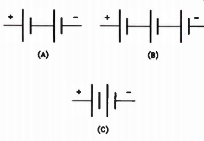
Figure 1. Battery symbols. Each cell is rated at 1.5 volts.
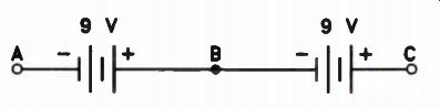
Figure 2. Two 9 V batteries connected in series.
Most people think of a flashlight cell as a battery, but technically it is a cell. The combination of two or more cells is a battery. A three cell combination, shown in Fig.1(B), has a total voltage of 4.5 volts. If we connect 15 cells as shown by Fig.1(C), we get a voltage of 15 x 1.5 = 22.5 volts. Notice that we did not draw 15 cells.
Usually two cells are shown, and the voltage is listed in numerals.
We can connect two 9 V batteries in series, as shown in Fig. 2, to get 18 volts. There is 9 V between terminals A and B, 9 V between terminals B and C, and 18 V between terminals A and C. Some times we say that terminal C is 18 V positive with respect to (or compared to) terminal A; or that terminal A is 18 V negative with respect to terminal C. If polarity is unimportant to the application, we may just say that there is 18 V between A and C. To simplify the wiring of most electronic equipment, a common terminal of the power source is frequently used as a reference point.
For example, terminal B is a common point with respect to the voltages at A and C. It is 9V positive with respect to terminal A, and 9V negative with respect to terminal C. This common terminal may be used as a reference point and is most frequently called ground, or some times a common ground. At the ground point, the voltage is considered to be zero because it is used as a reference value. When you read that some circuit point is at "ground potential," it means that the voltage at that sition--With respect to the common ground.
Usually, the negative terminal of the battery or power supply is connected to the common ground terminal as shown in Fig.3(A). Notice the symbol used to represent the ground connection. When connected in this way, terminal A is regarded as the zero reference point (the ground) for voltage in the equipment circuits. Terminal B would measure +9 V, and terminal C, +18 volts.
The common connection can also be made as shown in Fig.3(B). Here, terminal C connects to the common ground terminal, so the voltage at terminal C is 0 volts. Terminal B voltage is -9 V and terminal A has -18 volts. The net effect is the same as when terminal A is grounded; there is 18 V between terminals A and C. The difference is in the polarity of the voltage with respect to the ground reference point.
A third way of making the common or ground connection is shown in Fig.3(C), where terminal B is at ground potential. Terminal A is -9 V, and terminal C is +9 V with respect to the reference point, terminal B. There is still 18 V total between terminals A and C.
Most modern electronic equipment is made with printed circuit boards. These are thin, insulating boards to which a layer of copper conductor is glued. The copper is marked with the desired circuit pattern, then most of the copper is etched off the board by an acid solution, leaving the circuit conductor layout. Frequently, some excess copper is left on the board to form the common connection, also called the ground foil.
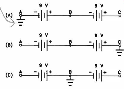
Figure 3. Three ways of adding a common or ground connection to two 9
V batteries connected in series. The voltage between the terminals is
the same in all three circuits.
Using the chassis as a common connection significantly reduces the amount of necessary wiring in electronic equipment. The same technique is used on a larger scale in automobiles, where the frame of the vehicle takes the place of a wire. The negative terminal of the automotive battery is bolted to the frame or chassis of the car. Current flow in automotive electrical accessories is from the chassis ground, through the accessory, then through a wire to the positive terminal of the battery This is why you will frequently see automotive electrical systems described as "12 V negative ground" systems.
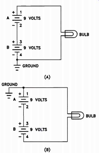
Figure 4. Simple circuits with ground connection.
In Fig. 4, one battery is labeled A and the other is labeled B. The positive terminal of battery A is terminal 1, and the negative terminal is terminal 2. The positive terminal of battery B is terminal 3, and the negative terminal is terminal 4. Notice that the negative terminal of battery B in Fig.4(A) is grounded.
With the batteries connected in this way, using ground as a reference, we say that terminal 1 of battery A is +18 V with respect to ground. Also, if the negative terminal (4) of battery B is at ground or zero potential, terminal 3 of battery B will be 9 V with respect to ground.
In Fig.4(B), the ground connection is moved so that terminal 1, the positive terminal of battery A, is ground. Now we consider terminal 1 of battery A to be at zero, or ground potential, and terminal 4, the negative terminal of battery B, is -18 V with respect to ground. Remember that the total voltage is the same in both cases.
As you've seen before, we can go one step further and ground the connections between terminals 2 and 3 of the two batteries, as shown in Fig.5. Here we have both negative and positive polarities with respect to ground. Terminal 1 of battery A is positive with respect to ground, and terminal 4 of battery B is negative with respect to ground. The total voltage applied to the bulb is still 18 V because the two batteries are connected in series. The same current flows through the bulb in the two examples given in Fig.4 and the circuit shown in Fig.5. In your study of electronics, you will run into a lot of equipment where voltages may be either negative or positive with respect to ground.
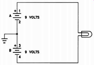
Figure 5. A simple circuit with a positive voltage with respect to ground
and a negative voltage with respect to ground.
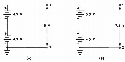
Figure 6. Batteries connected in series so their voltages add.
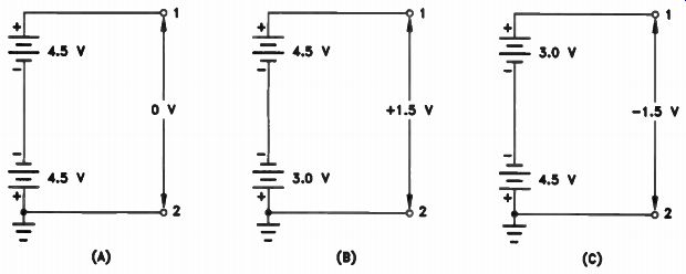
Figure 7. Batteries connected in series so their voltages subtract. (C)
Voltages in Series
Voltage sources can be connected in series.
Whether they add together or subtract from each other depends on how they are connected.
In Fig.6(A) we have two 4.5 V batteries connected in series aiding. This means that the two voltages add together. Notice that the batteries are connected in the same way as the cells forming each battery are connected. We have, in effect, simply added three additional cells to one of the 4.5 V batteries, so that the total voltage between terminals 1 and 2 is 9 volts.
In Fig.6(B), we have batteries with different voltages connected in series aiding. In effect, we have simply added two cells to the 4.5 V battery, so the total voltage is 7.5 volts.
In Fig.7, we have three examples of batteries connected in series opposing. These batteries are connected so that their voltages oppose. To find the total voltage we subtract the battery voltages.
In Fig.7(A), each battery is a 4.5 V battery.
When you subtract 4.5 from 4.5, the result is 0. Therefore, the potential between terminals 1 and 2 is 0 volts.
In Fig.7(B), we have batteries of unequal voltages. Subtracting the smaller voltage from the larger, we have 4.5 - 3.0 = 1.5 volts. Since the positive terminal of the larger battery connects to terminal 1, terminal 1 will be 1.5 V positive.
In Fig.7(C), we have the opposite situation.
The positive terminal of the 4.5 V battery connects to terminal 2. Therefore, terminal 2 is positive with respect to terminal 1, or, in other words, terminal 1 is 1.5 V negative.
We can connect de generators in series in the same way as the batteries shown in Figs.6 and 7. If they are connected in series aiding, their voltages add. If they are connected in series opposing, their voltages subtract.
Voltage Units
In many electronic circuits, the voltage values are not expressed in volts. Some values are much smaller, and require that the voltage unit be expressed in a more convenient unit of measurement. Occasionally, larger units are needed as well. For this reason, several useful voltage units have been defined.
The Millivolt. When the volt is too large a unit, we use the millivolt, and sometimes the microvolt. A millivolt, mV, is one thousandth of a volt. The prefix milli means one thousandth. To convert volts to millivolts we multiply by 1000. To do this, we simply add zeros and move the decimal point three places to the right. To convert from millivolts to volts, we do the opposite: divide by 1000 and move the decimal point three places to the left. Thus, 2. 5 V = 2. 5 x 1000 = 2500 mV. The Microvolt. The microvolt, abbreviated uV, is one millionth of a volt. The symbol µ is the Greek letter mu, and is traditionally used to indicate "micro." To convert volts to microvolts, multiply by 1,000,000. Do this by moving the decimal point six places to the right. To convert from microvolts to volts, move the decimal point six places to the left.
The Kilovolt. Another unit used in voltage measurements is the kilovolt. The kilovolt is 1000 volts. Thus, 25 kilovolts, abbreviated 25 kV, is equal to 25,000 volts. Voltages are measured in kilovolts in TV receivers, in video displays used with computers and microcomputers, and in radio and TV transmitters. Remember, a kilovolt is equal to 1000 V, so to convert kilovolts to volts, we simply multiply by 1000.
Review
A DC voltage produced by a battery or a DC generator will have a polarity that does not change. Connected to a circuit, a DC voltage source produces a current that flows in one direction. Voltage sources are frequently connected to common points called ground, and may be either positive or negative with respect to ground.
Batteries and generators can be connected in series aiding so that their voltages add, or in series opposing so that their voltages subtract.
When voltage sources are connected in series between ground and another point, the polarity of the point may be positive or negative when the batteries oppose, depending on the polarity of the larger voltage source.
Some circuits you will use will have very small voltages; others will have very high voltages. Remember that the millivolt (mV) is one thousandth of a volt, the microvolt (11V) is one millionth of a volt, and the kilovolt (kV) is one thousand volts.
Your understanding of the basic principles of electronics is essential. Advanced lessons are based on the fundamentals you learn in early lessons. If you skip over parts you do not understand, you are sure to run into problems later. If you have difficulty with some of the material, carefully reread those lesson sections. If you need additional help, take advantage of the NRI consultation service. Write and tell us exactly which section of the lesson gave you trouble, and we will give you additional assistance.
Self-Test Questions
1. In the circuit shown in Fig.4(3), if both batteries are 6 V, what voltage is present at terminal 4 with respect to ground?
2. In the circuit shown in Fig.5, if each battery (0 is a 45 V battery, what is the voltage at terminal 1 with respect to ground? What is the voltage at terminal 4 with respect to ground?
3. If a 15 V battery and a 45 V battery are , connected in series as in Fig.6(B), what will the voltage be at terminal 1 with respect to ground?
4. Two batteries are connected as shown in Fig. 7(B). One battery is a 45 V battery with its positive terminal connected to terminal 1, and the other battery is a 22-1/2 V battery with its positive terminal grounded. What is the voltage at terminal 1 with respect to ground?
---------------------
CURRENT
You have learned that an electron is part of an atom and that it has a negative electrical charge.
All electrons have the same negative electrical charge. Electrons repel each other because like charges repel. Electrons are repelled by negative charges, and attracted by positive charges.
Direct Current. When a battery is connected to an electric circuit, electrons are repelled from the negative terminal of the battery and attracted by the positive terminal. Electrons move in one direction through the circuit. This type of current flow is called direct current, or dc. Direct current is widely used in electronic equipment.
Current will flow through many of the devices used in electronic equipment in only one direction, and therefore the current used to operate these devices is direct current.
In a simple circuit, such as the one shown in Fig.8, the current flow is the same in all parts of the circuit at all times. The number of electrons leaving the negative terminal of the battery is exactly the same as the number of electrons passing point A on the wire connecting the battery to the lamp. The number of electrons flowing through the lamp is the same as the number of electrons passing point B on the other wire, and it is the same as the number of electrons moving into the positive terminal of the battery.
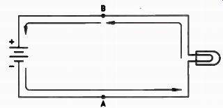
Figure 8. A simple circuit.
Another important point to remember is that electrons start moving in all parts of a circuit the instant the circuit is completed. Electrons do not leave the negative terminal, hit other electrons, and start a chain reaction of movement. All free electrons in the entire circuit start moving at the same time.
Alternating Current. The electric current sup plied to homes for light and power is an alternating current, or ac. Alternating current flows first in one direction and then in the other direction.
The current supplied by most power companies in the United States and Canada is 60-cycle current. This means that it goes through 60 cycles per second. We use the word hertz (abbreviated Hz) for cycles per second, so we say that the frequency is 60 Hz. In resistive circuits, alternating and direct current have the same relationships of current, voltage, and resistance.
We will discuss alternating current more fully in another lesson.
Current Units
The basic unit of current measurement is the ampere - abbreviated A - but in electronics this unit is often too large for convenient use. In common electronic circuits the current flow is small.
It may be only a few thousandths of an ampere.
The Milliampere. We can express three thousandths of an ampere (3/1000) more easily as a decimal, 0.003 ampere. But, it is more convenient to express the value in milliamperes (mA). A milliampere is one thousandth of an ampere. A current of three thousandths of an ampere is 3 milliamperes. To convert amperes to milliamperes, we simply multiply by 1000. This is done by moving the decimal point three places to the right. The process is similar to converting dollars to cents. One dollar is written in numerals as $1.00. To convert the $1.00 to cents, we move the decimal point two places to the right and we have 100e. To convert 5 A to mA, we can write 5 A as 5.000 amperes. Move the decimal point three places to the right and we have 5000 milliamperes. Similarly, if the current is 0.05 A, we can write it as 0.050 A, and move the decimal point three places to the right to give us 50 mA. In other words, to go from the large unit to the small unit, move the decimal point to the right.
To convert milliamperes to amperes, move the decimal point three places to the left. In other words, 47 mA can be written as 047. milli amperes. Moving the decimal point three places to he left, we have 0.047 ampere.
Note: A standard means of expressing any number less than one in decimal form includes placing a zero to the left of the decimal point.
---------------------------------
---------------------
LARGE TO SMALL
DOLLARS TO CENTS
$1 = 100e WE MOVED THE DECIMAL POINT 2 PLACES TO THE RIGHT
$1.00 = 100e AMPERES TO MILLAMPERES 1 A = 1000 mA WE MOVED THE DECIMAL POINT 3 PLACES TO THE RIGHT 1 A = 1.000 A 1.000 A = 1000 mA AMPERES TO MICROAMPERES 1 A = 1000000 µA WE MOVED THE DECIMAL POINT 6 PLACES TO THE RIGHT 1 A = 1.000000 A 1.000000 A = 1000000 MA
------------------------------
SMALL TO LARGE
CENTS TO DOLLARS
1000e = $10 WE MOVED THE DECIMAL POINT 2 PLACES TO THE LEFT 1000e = $10.00 MILLIAMPERES TO AMPERES 10 mA = 0.010 A WE MOVED THE DECIMAL POINT 3 PLACES TO THE LEFT
010. mA = 0.010 A 10 mA = 0.01 A MICROAMPERES TO AMPERES 1000000 µA = 1.000000 A WE MOVED THE DECIMAL POINT 6 PLACES TO THE LEFT 1000000 µA = 1.000000 A 1000000 µA = 1 A
---------------------

Figure 9. Examples of conversion from one unit to another.
-------------------------------
The Microampere. In some circuits even the milliampere is too large a unit. There is a smaller unit, the microampere, abbreviated uA. The microampere is one millionth of an ampere, just as a microvolt is one millionth of a volt.
To convert amperes to microamperes, move the decimal point six places to the right. In fact, try to remember that the decimal point always moves to the right when converting from large units to small units. Since there are a million microamperes in one ampere, we move the decimal point six places to the right. To convert milliamperes to microamperes, we move the decimal point three places to the right.
To convert microamperes to milliamperes, move the decimal point three places to the left.
To convert microamperes to amperes, move the decimal point six places to the left. In other words, 50 RA would be 0.000050 ampere.
In Fig.9 we have several examples of conversions from one unit to another. Study this figure and the conversions. Then try to do them your-self. This is the best way to learn how to convert from one unit to another. With a little practice, you will be able to convert from one unit to another as easily as you convert dollars to cents or cents to dollars.
Review We have reviewed current flow. Remember that current flow is a movement of electrons, and in a simple series circuit the current flow is the same in all parts of the circuit. When the circuit is complete, current starts to flow in all parts of the circuit at the same time.
You learned that the milliampere is one thousandth of an ampere, and the microampere is one millionth of an ampere. To convert from larger units to smaller units, move the decimal point to the right. In converting amperes to milliamperes (or milliamperes to amperes), move the decimal point three places; in converting amperes to microamperes (or microamperes to amperes), move the decimal point six places.
Self-Test Questions
5. If the current flow past a point in the circuit is 1 A and it is increased so that four times the number of electrons pass the point in a second, what will the new current be?
6. Convert $6.00 to cents. de p
7. Convert 2 A to mA.
8. Convert 0.42 A to mA.
9. Convert 0.037 A to mA.
10. Convert 0.002 A to mA.
11. Convert 46 mA to A.
12. Convert 822 mA to A.
13. Convert 2 A to µA. 000
14. Convert 0.0017 A to µA.
15. Convert 147 µA to A.
16. Convert 0.031 mA to µA.
17. Convert 327,000 µA to mA, and then to A.
RESISTANCE
All wires and components in electronic equipment have resistance. The resistance may be so low that it has no effect on the performance of the circuit; however, almost every circuit has some resistive component that affects the way it operates. In a DC circuit, the only factor that limits the amount of current that flows is the resistance in the circuit.
The Ohm
The unit of resistance is the ohm, named after pioneer scientist George Simon Ohm. Its symbol is the Greek letter omega (Omega). When an applied voltage of 1V causes 1A of circuit current, the circuit resistance is 1 ohm. What if an applied voltage of 2 V causes 1 A of circuit current? Since the current flow is 1A in both cases, the circuit in the second case has twice the resistance to current flow, or 2 ohms.
DC Resistance. DC resistance is the opposition offered to the flow of direct current in the circuit. If a DC voltage is applied to an electrical circuit, the DC resistance of the circuit will limit the current that will flow in the circuit. Usually, we call it resistance, rather than DC resistance.
AC Resistance. The AC resistance of a component may not be the same as the DC resistance.
At very high frequencies, much higher than the 60 Hz used by the power companies that supply electricity to your home, AC circuits have special characteristics that change the effective resistances. We will discuss these factors in greater detail in another lesson.
------
Carbon Resistors
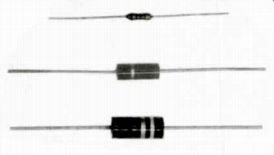
Carbon resistors come in several different sizes and in many different resistance values.
The size of the resistor tells you how much power the resistor can handle. Three different sizes of carbon resistors are shown here. Each resistor has a resistance of 1000 ohms. The resistor on the top is a 1 /2-watt resistor. The one in the middle can handle twice the power without burning up, and is a 1-watt resistor.
The one on the bottom is a 2-watt resistor, which can withstand four times the power of the 1 I 2-watt component. The watt is a unit of electrical power which we will discuss later.
----------
Wire-wound and Deposited-film Resistors
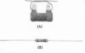
A wire-wound resistor (A) is made of wire wound on a form which is usually ceramic.
The wire used to wind a resistor is called resistance wire because it has a much higher resistance than copper wire. Wire-wound resistors are used in places where they must handle a higher current than could be handled by a carbon resistor.
The deposited-film resistor (B) is composed of a metal oxide film deposited on a ceramic form. These resistors can handle higher currents than carbon resistors, and can be made in larger resistance values than the wire wound type.
-------------
Resistors. You know that electronic circuits use copper wire to keep resistance low, but there are many instances where specific values of resistance are needed in the circuit for various reasons. Parts designed to add resistance to the circuit are called resistors. There are many different values, physical sizes, and types of resistors used in electronic equipment. The most commonly used type, the carbon resistor, is a mixture of powdered carbon and a cement-like material that bonds the carbon together. By varying the composition of the mixture, different values of resistance are obtainable, from less than an ohm up to several million ohms.
Resistance Units
Some electronic circuits require resistances of several thousand ohms, others may use values greater than a million ohms.
Kilohm. For convenience, one thousand ohms are represented by the letter k (kilo), so 1-k is 1 kilohm. A resistance of 2200 ohms is expressed as 22k. A resistor having a resistance of 100,000 ohms would be labeled 100k. A resistor with a resistance of 470,000 ohms would be labeled 470k.
Megohm. Megohm units (M) refer to resistors larger than one million ohms. A 2,200,000 resistor would be labeled 2.2M. Resistor values below a megohm may occasionally be expressed in megohms. For example, a 470,000 ohm resistor could be labeled 470k, or 0.47M. Converting back and forth between ohms, kilohms, and megohms is the same process as converting between amps (amperes), milliamps, and microamps, except that the ohm is the basic unit, and we typically work with larger values than one ohm. To convert from the small unit to the larger unit, simply move the decimal point to the left, either three places for kilohms or six places for megohms. To convert from the larger unit to the smaller unit, move the decimal point in the opposite direction to the right. This may seem very complicated, but don't be concerned about it. You will see all three terms, ohms, kilohms, and megohms so often that converting from one to another will become automatic.
Review
In a DC circuit the current flow is limited by the circuit resistance. The unit of resistance is the ohm. If a current of 1 A flows in a circuit when a voltage of 1 V is applied to the circuit, the resistance in the circuit is 1 ohm.
Three important types of resistors that you will encounter in electronic equipment are the carbon resistor, the wire resistor and the metal oxide i m resistor. These resistors are made in various resistance values and sizes to handle different values of current.
In many electronic circuits, the resistance is so high that we use the kilohm, which is equal to 1000 ohms, and the megohm, which is equal to 1 million ohms.
Self-Test Questions
18 If the current flow in a circuit is 1 A, and we double the resistance in the circuit, will the current increased- ese, reaor remain the same?
19 Name three types of resistors commonly used in electronic equipment.
20 Convert 4700 ohms to k.
21 Convert 5,600,000 ohms to M.
22 Convert 0.330M to k.
23 Convert 2.2M to ohms.
24 Convert 8.2k to ohms.
25 Convert 680k to M.
-------------------
OHM'S LAW
Ohm's law is one of the most important laws in electronics. It tells us how the voltage, current, and resistance are related in an electrical circuit. Ohm's law states that the current flow in a circuit is equal to the voltage divided by the resistance. Rather than using words to express this law we use symbols. We use the letter I for current. E for voltage, and R for resistance.
With this expression, if we know any two of the three values - resistance, current, or voltage--we can determine the third.
For example, we can interchange the R and I and we have the formula:
E R - -- 1
This formula tells us that the resistance in a circuit is equal to the voltage divided by the current. We can also express this formula as:
E = IR
This tells us that the voltage in a circuit is equal to the current flow in the circuit multiplied by the resistance in the circuit.
The importance of the three forms of Ohm's law is that they show us how the current, voltage, and resistance in a circuit are related. As we will see in the following sections, a change in either the voltage or the resistance in the circuit will result in a change in the current.
How Voltage Affects Current
Now we are going to use Ohm's law in the form:
E I = - R
This formula shows how a change in the applied circuit voltage affects the current in the circuit.
In Fig.10 we have a simple circuit consisting of a voltage source and a resistor. Notice the schematic symbol for a resistor; this is another important symbol you should remember. The battery voltage (E) is 20 V; the resistance (R) of the resistor is 2 ohms. The unknown value is the amount of current.
We can determine the circuit current using Ohm's law. We simply substitute the numeric values of voltage and resistance for E and R in the formula, then divide to give us the value of I:
20 = - = 10 A 2 E = 20 R = 2
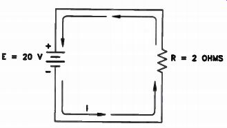
Figure 10. A simple circuit consisting of a voltage source and a resistor.
In the circuit shown in Fig.10, the current flow will be equal to 10 amperes. If we increase the voltage to 40 V, the new current flow will be: 40 = 20 A
If we reduce the voltage to 10 V, the current flow in the circuit will be:
I= L 0 = 5 A 2
Notice in each example that the current flow is directly related to the voltage. Increasing the voltage increases the current; reducing the voltage reduces the current. In the example where the voltage doubled, the current doubled. When the voltage was cut in half, the current was cut in half. This relationship will always hold true.
If we increase the voltage to three times the original value, the current will increase to three times the original value. If we reduce the voltage to one third of its original value, the current will be reduced to one third of its original value. As long as resistance remains the same, any change in the voltage will result in a direct change in the current.
How Resistance Affects Current
In the simple circuit shown in Fig.10, where the voltage is 20 V and the resistance 2 ohms, we found by using Ohm's law that the current flow is 10 amperes. The same circuit is shown in Fig.11, except that we have replaced the 2-ohm resistor with a 4-ohm resistor. How will this affect the value of I? Using Ohm's law, we can find the current:
I= - E = - 20 = 5 A R 4
Here the current is 5A, half the value it was before. Doubling the resistance cut the current in half. Suppose that, instead of doubling the resistance from 2 ohms to 4 ohms, we cut the resistance in half, reducing it from 2 ohms to 1 ohm. Using Ohm's law, we can easily find out what happens:
I = - 20 = 20 A 1
Cutting the resistance in half doubled the current from 10 A to 20 amperes.
This relationship between current and resistance holds true regardless of how we change the resistance. If we increase the resistance to three times its original value, the current decreases to one third the original value. If we cut the resistance to one third its original value, the current increases to three times its original value. We say that current varies "inversely" with respect to resistance. If the resistance increases, the current decreases. If the resistance decreases, the current increases.
1 II E = 20 V - R = 4
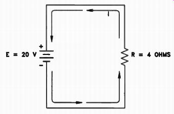
Figure 11. The 2-ohm resistor in the circuit of Fig.10 is replaced by
a 4-ohm resistor.
This relationship between current and resistance is obvious if we examine Ohm's law. Look at the expression for current below:
E I = - R
If E remains constant and we increase R, it is obvious that I must become smaller, because E is divided by a larger number. If we reduce R, and keep E constant, I must get larger.
Finding E
In some circuits, we may know the values of current and resistance, but we want to find the voltage in the circuit. An example of this type of problem is shown in Fig.12. Here the current is 2 A and the resistance 15 ohms. We want to find the value of E using Ohm's law: E = IR We can substitute for the values of I and R and get:
E = 2 x 15
= 30 V
Thus, the value of the voltage applied to the circuit must be 30 volts. If we measured a circuit current increase to 3 A, and the resistance remained 15 ohms, we would know that the voltage applied to the circuit had increased to 45 V, because:
E = IR
E = 3 x 15
E = 45 V
Notice that in all of the examples we've given using Ohm's law, the voltage is in volts, the current is in amperes, and the resistance is in ohms. However, the current may be expressed in milliamperes or microamperes. In such a case, you must convert the value to amperes to use Ohm's law. Similarly, the resistance may be in kilohms or megohms. Again the value must be converted to ohms.
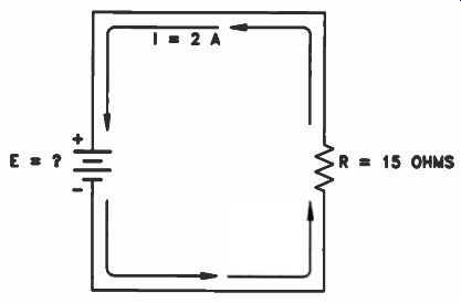
Figure 12. A simple circuit where I = 2 amperes and R . 15 ohms.
Review
We have seen how circuit current is affected by the applied voltage and by the circuit resistance. We found that increasing the voltage increased the current, and decreasing the voltage decreased the current. We said that the current varies directly to the voltage. In the case of the resistance in the circuit, we found it had the opposite effect on the current. Increasing the resistance of the circuit decreased the current, and decreasing the resistance increased the current. The current is said to vary inversely to the resistance.
You should remember the three forms of Ohm's law so that you can see how each of the three quantities - current, voltage, and resistance, is affected by changes in the other two. The three forms of Ohm's law are:
Remember that to use Ohm's law, the voltage if the voltage must be in volts, the current in amperes, and the resistance in ohms.
Self-Test Questions
26 Give the form of Ohm's law that is used when you know the voltage and current, and want to find the resistance.
27 Write the Ohm's law formula that is used when you know the current and resistance E = IR in the circuit, and want to find the voltage.
28 Write the Ohm's law formula that is used when you know the voltage and resistance R E in the circuit, and need to find the current.
29 In the circuit in Fig.10, find the current if the voltage is 15 V and the resistance is 3 ohms.
30 If in the circuit in Fig.11, the voltage is 60 V and the resistance is 15 ohms, what is the current? 31 If the current in a circuit is 3 A and the resistance is 20 ohms, what is the voltage?
ANSWERS TO SELF-TEST QUESTIONS
1 -12 V.
2. Terminal 1 is +45 V, and terminal 4 is -45 V.
3 +60 V. The two batteries are connected in series aiding, and therefore their potentials will add, 15 + 45 = 60 V. The terminal is positive because it is connected directly to the positive terminal of one of the batteries.
4. +22-1/2 V The two batteries are connected to oppose each other, and thus their voltages subtract. 45 V - 22-1/2 V = 22-1/2 V.
The polarity will be that of the higher voltage battery, which is the 45 V battery. Since its positive terminal is connected to terminal 1, terminal 1 will be positive.
5. 4 A. If the original current was 1 A and the number of electrons increased by four times, the new current must be 4 A. 6 $6.00 = 600e.
7 2 A = 2000 mA.
8 0.42 A= 420 mA.
9 0.037 A = 37 mA.
10 0.002 A = 2 mA.
11 46 mA = 0.046 A.
12 822 mA = 0.822 A.
13 2 A = 2,000,000
14 0.0017 A = 1700 !
15 147 pe = 0.000147 A.
16 0.031 mA = 31 t,k.
17 327,000 uA = 327 mA = 0.327 A.
18 The current will decrease. If we double the resistance in the circuit, the current will be cut in half.
19 Carbon resistors, wire-wound resistors, and metal oxide film resistors.
20 4.7k. In order to convert 4700 ohms to kilohms, we move the decimal point three places to the left.
21 5.6M. In order to convert 5,600,000 ohms to megohms, we move the decimal point six places to the left.
22 330k. In order to convert megohms to kilohms, we move the decimal point three places to the right.
23 2,200,000 ohms.
24 8200 ohms.
25 0.680M. In order to convert kilohms to megohms, move the decimal point three places to the left.
26 E R = - I
27 E = IR
28. T E - - R
29. 5 A. To solve this problem use the formula: E I = - R Substituting 15 V for E and 3 ohms for R, we get: 15 3
30. 4 A. To solve this problem, use the formula: I= Substituting 60 V for E and 15 ohms for R, we get: I = 0= 4 A 15
31. 60 V. To solve this problem, use the formula: E = IR Substituting 3 A for I and 20 ohms for R, we get: E = 3 x 20 = 60V
Lesson Summary
Some of the important facts that you should remember about this lesson are:
• When connected to a circuit, a DC voltage source causes current flow in one direction.
• Voltage sources use common points called grounds.
• A point in a circuit may be either positive or negative with respect to ground.
• Batteries and generators connected in series aiding will add their voltages. In series opposing, their voltages subtract.
• Current flows in all parts of the circuit at the same instant when voltage is applied.
• Current, voltage, and resistance units may be conveniently expressed in smaller or larger units for ease of measurement.
LESSON QUESTIONS
This is Lesson Number 2217.
Make sure you print your name, student number, and lesson number in the space provided on the Les son Answer Form. Be sure to fill in the circles beneath your student number and lesson number.
Reminder: A properly completed Lesson Answer Form allows us to evaluate your answers and speed the results and additional study material to you as soon as possible. Do not hold your Lesson Answer Forms to send several at one time. You may run out of study material if you do not send your answers for evaluation promptly.
1. If a 9 V battery and a 6 V battery are connected in series aiding, the total voltage of the two batteries will be: a> 15 volts.
b. 3 volts.
c. 9 volts.
d. 6 volts.
2. If a 6 V battery and 4 V battery are connected in series opposing, the total voltage across the two will be:
a. 6 volts.
b. 4 volts.
2 volts.
d. 10 volts.
3. A common point on the wiring connections, tied to the negative side of the power source, is called a:
a. Lug.
4. Ground.
c. Node.
d. Chassis.
4. A voltage of 20 mV is equal to how many volts?
a. 20 volts.
b. 2 volts.
c. 0.2 volts.
d. 0.02 volts.
5. If the current flow in the circuit is 2A when the voltage is 5 V, what will the current be when the voltage is raised to 20 volts?
a. 1-1 2 amperes.
b. 4 amperes.
c. 8 amperes.
d. 20 amperes.
6. If the current flow in the circuit is 4A when the resistance is 2 ohms, what will the current be if the resistance is increased to 8 ohms?
a. 1 ampere.
b. 2 amperes.
c. 4 amperes.
d. 8 amperes.
7. If the voltage applied to a circuit is 20V and the resistance is 4 ohms, the current will be:
a. 20 amperes.
b. 10 amperes.
c. 5 amperes.
d. 1 ampere.
8. If the current flow in a circuit is 8A and the resistance is 2 ohms, the voltage will be:
a. 4 volts.
b. 8 volts.
c. 12 volts.
d. 16 volts.
9. If the voltage in a circuit is 100 V and the current is 1 A, then the resistance is:
a. 1 ohm.
b. 10 ohms.
c. 100 ohms.
d. 1000 ohms.
10. If the current flow in a circuit is 6 mA and the resistance is 6k, what will the current be if the resistance is changed to 3k?
a. 3 milliamperes.
b. 6 milliamperes.
c. 9 milliamperes.
d. 12 milliamperes.
------------
NRI Schools
EACH DAY COUNTS
Each day of our life offers its own reward for work well done, its own chance for happiness. These rewards may seem small, and these chances may seem petty in comparison with the big things we see ahead.
As a result, many of us pass by these daily rewards and daily opportunities, never recognizing that the final goal, the shining prize in the distance, is just a sum of all these little rewards we must win as we go along.