AMAZON multi-meters discounts AMAZON oscilloscope discounts
Table of Contents
Overview
Experiment 1: Kirchhoff's Voltage Law
Experiment 2: Voltage in a Series-Connected Circuit
Experiment 3: Voltage Polarity
Experiment 4: Measuring Voltage to Determine Current
Experiment 5: Series Voltage Dividers
Experiment 6: Electrical Power Preparing for Experiments 7-9
Experiment 7: Using an Ohmmeter
Experiment 8: Circuit Continuity
Experiment 9: Parallel Resistance
Experiment 10: Charging and Discharging Capacitors
Experiment 11: Basic Coil Action
Experiment 12 : Transistor Operation
Examination Questions
Objectives
Upon completion of this lesson you will:
• Configure components using schematic diagrams and measure the voltage, resistance, and current within the circuits.
• Determine open and shorted components using a multi meter.
• Configure components in a circuit to observe effects of a bleeder resistor.
• Determine the power factors of a circuit by taking appropriate measurements throughout the circuit.
• Determine best range to use when measuring resistance with an ohmmeter.
• Determine the status of a transistor as it operates within a circuit.
Overview:
This training manual contains your digital multimeter, complete with test leads, operating manual, and electronic parts to be used in the experiments. Your first step in performing the experiments is to study the section in this manual on using the digital multimeter.
If you are already familiar with digital multi meters, the information and instructions pro vided will serve as a review.
This training manual features practical experiments that demonstrate some of the electronic fundamentals discussed in your lessons. Each experiment is an actual working demonstration. The principal objective of this training manual is to provide you with hands on experience that illustrates basic electronic concepts. Another goal is to develop your ability to visualize a circuit and wire it using only a schematic diagram as your guide.
As you perform each experiment, try to understand what happens in the circuit. For example, if an LED (light-emitting diode) glows brighter when you change the amount of resistance in a circuit, what basic circuit characteristic changed and why? Did the applied voltage change? Did the current change? Does the circuit configuration also affect the result? If you learn to ask yourself these types of analytical questions, you can gain a better understanding of electronics and electronics troubleshooting.
The best way to complete this training manual is to perform each experiment in sequence. Don't hurry to finish any experiment, even if you feel you already know what the results will be. We also encourage you to review your regular lesson materials for additional information on each subject discussed in this manual.
This training manual also contains a soldering project, the purpose of which is to pro vide you with soldering practice. You may assemble your soldering project whenever you like. However, most students prefer to wait until they have completed all of the experiments in this training manual before they work on the soldering project.
Preparing for the Experiments
You will build circuits with resistors, capacitors, a transistor, LEDs, and a coil. Nine volt batteries (included) supply power for the breadboard on which you will connect the circuits. The battery clip leads and the coil leads are stranded wire. They don't plug into the breadboard easily. To make attaching the stranded-wire leads easier, solder a length of hook-up wire to them. Since hook-up wire is solid, it can be inserted easily into the holes of the breadboard socket.
Cut three pieces of white hook-up wire and three pieces of black hook-up wire in 3" lengths. Strip 1/4 " of insulation from the ends of these wires. Also strip 1/4" of insulation from the battery clip and coil leads. Splice the black hook-up wire pieces with the black leads of the battery clips and the white hook up wire to the red leads. Solder these joints together as shown in Figure 1.
Solder the remaining black and white wire pieces to the leads of the coil. Since the coil is not polarized, it makes no difference what color hook-up wire you use for each lead.
Using the Breadboard Socket
You will build the experimental circuits on a breadboard that is similar to the bread board shown in Figure 2 on the next page. A breadboard provides a large number of multipin wire-sockets that allow you to connect electronic circuit components together with out using solder. The design of the bread board also lets you add or change components easily.
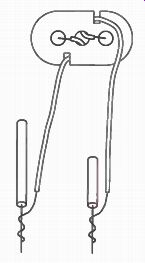
Figure 1. Splice hook-up wire to the leads of the battery clip.
On the breadboard, notice the two rows at the top and bottom labeled with a + and - sign. The wire-sockets in each of these four rows are connected. This type of connection is called a bus, and it comes in handy for convenient connections to power supply voltages.
Each hole in the top row (blue) is connected to every other hole in the row. Likewise, all the holes in the second row (red) are connected to each other. The red and blue rows, however, are not connected to each other. You could, for example, connect the positive and negative leads from a battery to the red and blue rows and have access to voltage along the length of the breadboard.
Refer to Figure 3 on the next page. The center section of the breadboard holds 126 five-slot connectors, arranged in two rows of 63 connectors each. Each of the five-hole columns is separate from the others, but the five holes in each one are connected. In fact, the back side of the breadboard is a collection of slots, each filled with a conductive spring-clip that covers five holes. Most of your experiments will use the center section of the bread board, while power supply (battery) connections typically insert into the blue and red buses.
Using Your Digital Multimeter (DMM)
Your DMM has multiple functions, plus a diode test position. It can measure AC and DC voltages and AC and DC current, as well as resistance. The rotary switch in the center of the DMM selects all functions and ranges. Typically, when the rotary function switch is pointing in the vertical position (or 12 o'clock), the DMM is in the OFF position.
In a clockwise direction from the OFF position (roughly 12 to 5 o'clock) are the voltage functions. Moving in a counterclockwise direction are the resistance and diode test functions (roughly 9 to 12 o'clock). The current functions are found between the other two function areas (approximately 5 to 9 o'clock). On some models a separate switch might be used to select the proper AC or DC function.
However, the rotary switch is used to select AC or DC functions on this model. Each function may have three to five ranges, depending upon the meter design.
Some multimeters have a capacitance function, but it is not included with this particular model. One of the unique features is being able to test NPN and PNP transistors using an visual indication or audible tone to indicate a good test.
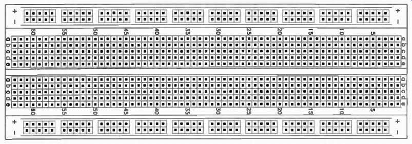
Figure 2. The breadboard socket used during these experiments.
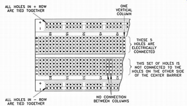
Figure 3. The breadboard socket is designed to provide a method of connecting
components without soldering.
Test lead jacks are usually are located on the bottom of the DMM. One jack is marked COM. This is the common jack; it is used for all types of measurements. This jack is often -referred to as the ground or negative jack.
Normally, you will plug the black test lead into this jack. The black test lead remains in this jack when taking voltage, current, and resistance measurements.
A jack marked V/12 is used for both DC and AC voltage measurements and resistance measurements. The V represents voltage, and the S1 represents resistance. When the voltage and resistance measurement functions are used, the red test lead is plugged into this jack.
The jack marked mA is used for both DC and AC current measurements between 0 and 200 milliamps (mA). There is also a jack marked A which is used for both DC and AC current measurements between 200 milliamps (mA) and 20 amps (20 A). When you are going to use the DMM to measure current, initially you should keep the black lead in the COM jack and plug the red lead into the A jack. This is a safety precaution when measuring current, especially when it is un known. Thereafter, to measure current that is known to be lower than 200 mA, plug the red test lead into the mA jack.
The best way to become familiar with your DMM is by using it. In this training manual, you will be instructed to take DC voltage and DC current measurements. You also will take resistance measurements. In the next training manual, you will learn how to use the AC voltage ranges of the DMM. The procedures for measuring AC current are rarely used, and will not be covered in this course. However, please note that current measurement procedures are the same for both AC and DC. In the early experiments, as you are learning how to use your DMM, you will be informed of how to set the range switch for voltage and/or current measurements. With practice, you should be able to determine for yourself the proper range to use.
There is one safety procedure that must be followed when measuring unknown voltages or currents. You should always start with the highest range to avoid damage to the meter. The meter has a built-in fuse that is designed to protect it, but it is possible to damage the meter before this fuse blows.
For example, suppose you want to measure an unknown DC voltage. You should set the range switch to the highest volt range on the DCV function. Let's say that the highest range is 1,000 volts. If the reading you get on the meter indicates that the voltage is substantially less than 1,000 V, then you can switch to the next lowest position that does not cause an overload indication. By using this procedure, you will avoid the possibility of damaging the meter. If you start out measuring the voltage on the 200 V position, for example, and the voltage is very high perhaps 700 or 800 V you could damage the meter.
But if you start off on the highest DCV position, you'll see that the voltage is high and know that you should not switch the range switch to a lower voltage position.
The same is true when taking current measurements. Start in the highest current position and switch to a lower range if you see that the current is much lower than the range selected.
This is only preliminary information on your DMM. You will learn more about your DMM and how to use each function as you per form the experiments. We recommend that you do not use the DMM for any measurements other than those in the experiments until after you have completed this training manual. By that time, you will have had sufficient instruction on how to use each function of the meter.
These instructions will reduce the possibility of accidental damage to the meter due to in correct use.
Performing the Experiments
In performing your experiments, be sure to follow these steps:
Step 1. Read the entire experiment and pay particular attention to the discussion of the experiment.
Step 2. Perform the experimental procedure and each step of the experiment exactly as directed. Record your results in the charts or tables provided for that purpose.
Step 3. Study the discussion of the experiment and analyze your results. If they do not seem to be right, repeat the measurements to make sure that you did not make a mistake.
Do not move on to the next experiment until you get the desired results.
Step 4. You will notice instructions to turn off the DMM at the end of many of the experiments. However, it is not necessary to turn off the instrument if you are going to perform more than one experiment without stopping.
The DMM draws so little current that the battery usually will last a year or more before needing replacement. These instructions are given as a reminder. Turn off the DMM after you have performed all of the experiments that you are planning to do at one time.
The experiments in this manual will familiarize you with the operation of your digital multimeter (DMM). At the same time, you will learn the causes of incorrect voltage and resistance measurements in electronic circuits.
You are now ready to begin learning how to troubleshoot with a DMM. Keep in mind that taking measurements is only the beginning. What you can do with the results of your measurements is what really counts.
The DMM supplied in this kit is a very reliable and accurate servicing instrument. It was designed by service engineers for the service expert. Learn to use it properly, and it will be your most powerful tool. It will give you information quickly and accurately. Your regular lessons in conjunction with these experiments will teach you how to apply this in formation.
Caution: Your DMM has a fuse that pro vides built-in protection against an accidental overload. However, it is still possible to dam age your meter. Be sure that you read the instructions carefully and fully understand them before proceeding with the experiments. These precautions will eliminate the possibility of an accident that could result in serious damage or injury.
-----------------------
Experiment 1: Kirchhoff's Voltage Law
Introduction
The source voltage across a series of resistors causes current to flow through the resistors. This current produces a voltage drop across each resistor. Regardless of how many resistors are used in the circuit, each one will have a voltage drop across it that is related to the current and resistance. The higher the resistance, the more voltage is required to push current through it.
In your regular lessons, you learned about Kirchhoff's voltage law. This law states that the sum of the voltage drops around any closed circuit equals the source voltage. Consider the circuit shown in Figure 1-1. By di viding the source voltage (10 V) by the total circuit resistance (6.7k), we find that the current flow in this circuit is 1.49 milliamps.
Once we determine the current, we can prove Kirchhoff's voltage law by calculating the voltage across each resistor and then adding these values together. The total should equal the source voltage.
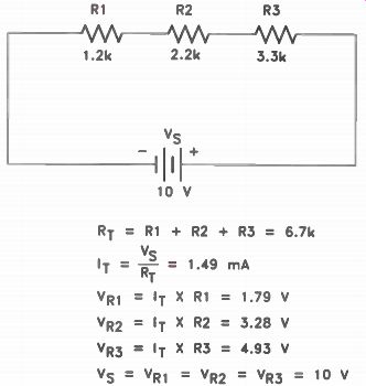
Figure 1-1. Applying Kirchhoff’s law to a simple series circuit
Modern digital multimeters have a very high and constant input resistance. This high input resistance means that the total resistance you are connecting across the circuit will not affect the circuit, regardless of the meter range you are using. Thus, voltage readings in low-voltage circuits are much more accurate. However, even this meter can upset the voltage distribution in very high-resistance circuits.
Materials Needed
In this experiment, you will need:
Breadboarding socket; Digital multimeter ;1 9 V battery with the battery clip attached; 1 10k resistor; 1 100k resistor; 1 470k resistor; 1 1M resistor; 2 10M resistors
Procedure
If you need to do so, install the battery that was supplied with the DMM. Also, plug the black meter lead into the jack marked COM and the red lead into the jack marked V.
In this experiment, you will breadboard a simple series circuit and use your DMM to measure the voltages in the circuit. Begin by wiring the circuit in Figure 1-2. A pictorial of how the circuit might be arranged is shown in Figure 1-3, on the next page. When you have finished, turn the DMM selector switch to 20-V DC.
Step 1. To measure the source voltage, touch the black lead of your meter to the junction of R1 and the negative lead of the battery.
Touch the red lead to the junction of R3 and the positive lead of the battery. Record your reading for Step 1 in Table 1-1, on the next page.
Step 2. Measure the voltage drop across R1 (10k) by touching the black lead of your DMM to the end of R1 that connects to the negative terminal of the battery and the red lead to the junction between R1 and R2. Record your reading for Step 2 in Table 1-1.
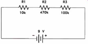
Figure 1-2. Schematic of the series circuit for Experiment 1.
Step 3. Measure the voltage drops across R2 (470k). Reposition the black lead of your DMM to the junction of R1 and R2 and touch the red lead to the junction between R2 and R3. Record your reading for the voltage across R2 in Table 1-1.
Step 4. Lastly, you will measure the voltage drop across R3 (100k). Move the black lead to the junction of R2 and R3 and touch the red lead to the junction between R3 and the positive terminal of the battery. Record your measurement in Table 1-1. Now, Total the voltage drops you measured across R1, R2, and R3 and compare this value to the source voltage you recorded in Table 1-1. How does the sum of the voltage drops compare to the source voltage you measured in Step 1? Step 5. Wire the circuit shown in Figures 1-4, on the next page, on your breadboard socket. Be sure to connect R2 in parallel with R3, and one end of R1 to the junction of R2 and R3. A pictorial is provided in Figure 1-5, on page 9.
Step 6. Measure the source voltage by touching the black lead of your DMM to the negative terminal of the battery and the red lead to the positive terminal of the battery. Record your measurement in Table 1-2.
Step 7. Measure and record the voltage drops across each resistor like you did in Steps 2-4. Notice that the voltage drop across R2 and R3 is the same, even though the resistance of R2 is different from R3. When a voltage source is equally applied across two or more electronic components, the components are said to be in parallel.
Also, notice that the voltage across R1 is greater in this experiment than it was in the series circuit using the same resistors. Unlike a series circuit, the more components we add to a parallel circuit, the more source current will flow in the circuit. That's because in a parallel circuit, the total resistance decreases as you add more components to the parallel network. The higher voltage across R1 is an indication that the total source current is higher.
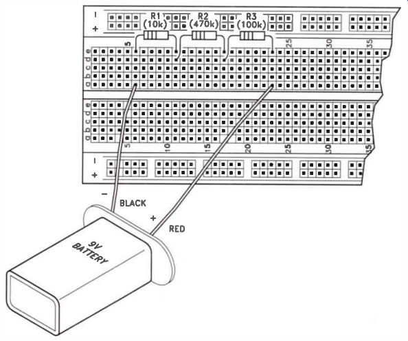
Figure 1-3. An illustration of the circuit for Steps 1 and 2.
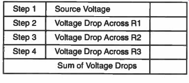
Table 1-1. Record your readings for the circuit in Figure 1-1 here.
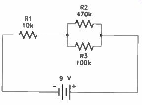
Figure 1-4. Kirchhoff's voltage law also applies to combinational-combinational
circuits.
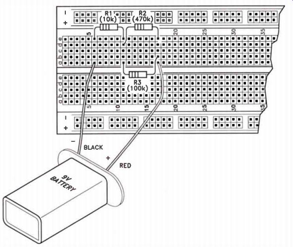
Figure 1-5. An illustration of the circuit for Step 3.
When you measure the voltage across a component, the meter's internal resistance is placed in parallel with it. Like any other parallel combination, the combined resistance is less than the internal resistance of the meter or the resistance of the component.
As long as the resistance of the component is substantially smaller than the internal resistance of the meter, you'll get accurate readings. But, if the resistance of the component is extremely high, the combined internal resistance of the meter and the resistance of the component could cause an inaccurate reading. In this case, we say that the meter loads down the component. To demonstrate, reconstruct the circuit shown in Figure 1-2 on page 7, using two 10M resistors and one 1M resistor.
Repeat steps 1 through 4 and notice that the sum of the individual voltage drops does not equal the source voltage. This proves that measurement errors can occur in very-high resistance circuits. Fortunately, circuits with this much resistance are rare, but they do exist. Disconnect the battery from your circuit.
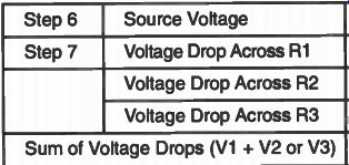
Table 1 - 2. Record your results for Step 3 here.
Results
In this experiment, you proved that in a series circuit the sum of the voltage drops across the individual components is equal to the source voltage.
When you connect your meter across a resistor, you are adding the resistance of the meter in parallel with the resistance of the resistor. This changes the resistance in the circuit slightly. Your meter has an internal resistance of around 22 megohms. When you connected it across the 100k resistor, the resistance of the parallel combination became 99,548 ohms. You saw that the change is small it was less than 500 ohms, which is less than 0.5 percent. This small change means that the voltage reading you'll get will be quite accurate.
Years ago, service technicians used meters that had a sensitivity of 20,000 ohms per volt. Thus, on a 5 V range, a meter of this type will have a total resistance of 100,000 ohms. If you use this type of meter and connect it across the 100k resistors in this experiment, you would change the resistance to 50k. The resulting voltage reading you would get would be quite inaccurate.
This experiment demonstrates the value of a high-resistance meter in voltage measurements, particularly in low-voltage circuits.
However, even this meter can cause erroneous measurements in high-resistance circuits.
-------------
Experiment 2: Voltage in a Series-Connected Circuit
Introduction
You know from the experiments you have already performed that when current flows through a resistance, there is always a voltage drop across the resistance. You also know that current flows only in a circuit with continuity.
Continuity, as used in electronics, refers to the completeness of the path through which current flows. If there is no continuity, or, in other words, if the path is broken at some point, current cannot flow. These facts are of great importance to the technician. They are used constantly in troubleshooting.
A complete circuit has a voltage source, one or more parts through which current can flow, and wires or leads that connect parts together and to the voltage source. The parts in the circuit do not necessarily have to be resistors. However, all parts through which current is able to flow have some resistance.
Examples of other parts are coils, transformers, and transistors. The fact that such parts have some resistance means that there will be a voltage drop across each part when it is connected in a circuit with a voltage source.
Certain defects are evident when the voltage drop at some point in a circuit is either too high or too low. You can get a fairly good idea of what the voltage drop in each part of the circuit should be by looking at the schematic diagram. For example, if there are three resistors having the same resistance in a series circuit, you should find that the voltage drop across each of the resistors is equal to about one-third of the source voltage. On the other hand, if one very high resistance is in series with one or more low resistances, then the voltage drop across the high resistance will be very nearly equal to the source voltage, and the voltage drop across the low resistance will be almost zero.
If there is no voltage drop across one part in a circuit but there is a voltage drop across the other parts, there must be a short circuit, or a path with no resistance, across the part with no voltage drop. Thus, the current flows through the short circuit rather than through the part. Because the resistance is essentially zero through the short, there is no voltage drop across it.
If you measure the whole source voltage across a part in a series circuit, you can assume that the part is open (will not pass current). The full source voltage across the part indicates that there is no voltage across the other parts in the circuit and therefore no current flowing through them. The break is in the part across which you measured the source voltage. You will investigate these conditions in this experiment so that when you come across them in service work, you will know what to expect.
Materials Needed
To perform this experiment you will need:
Breadboarding socket
Digital multimeter
1 9 V battery with the battery clip attached 2 1-k resistors 1 2.2k resistor 1 10k resistor
Hook-up wire
Procedure
Begin by cutting two pieces of wire about 2" long and removing about 1 / 2 " of the insulation from both ends of each wire. Twist the two wires together as shown in Figure 2-1.
When the top portion is connected as shown, the twisted pair will be used to simulate a shorted resistor. When the top is untwisted, the twisted pair will be used to simulate an open resistor.
TWIST THE TOP EXPOSED WIRES TOGETHER
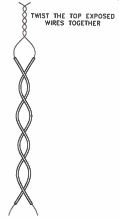
Figure 2-1. Illustration of a twisted pair of wires.
Now construct the circuit shown in Figure 2-2. Your wiring should look something like the illustration in Figure 2-3.
Step 1. Examine Figure 2-2. Notice that R1, R2, and R3 form a series circuit and are connected across the 9 V battery. R4 is not in the circuit.
Put the DMM on the 20 V DC range and measure the source voltage. The black lead from your DMM should connect to the negative terminal of the battery, and the red meter lead should connect to the positive battery terminal. Record your reading in the Normal Resistance column of Table 2-1.
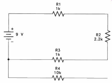
Figure 2-2. Schematic of the circuit for Experiment 2.
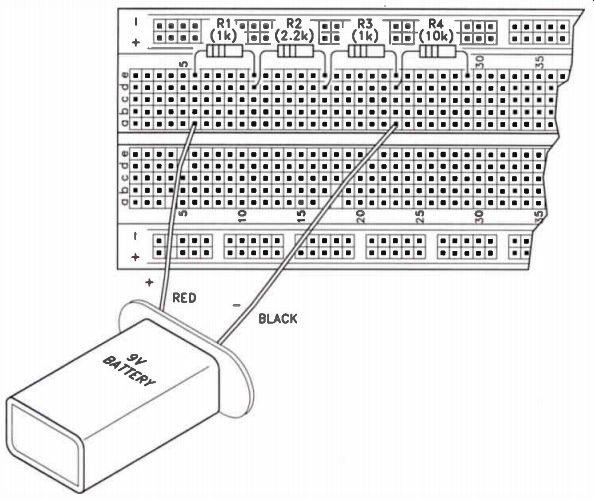
Figure 2-3. Pictorial of the circuit for Experiment 2.
• Step 2. Next, measure the voltage drop across R1, R2, and R3 and record these voltages in Table 2-1. Remember, the end of a resistor where electrons enter will be negative with respect to the other end of the same resistor. For example, to measure the voltage across R2, touch the black lead of your DMM to the end of R2 that is closest to the negative terminal of the battery, and touch the red lead to the other end of R2.
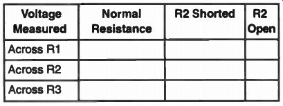
Table 2-1. Record your results for Experiment 2 here.
Step 3. Notice that a voltage drop developed across R1, R2, and R3. These voltages indicate that current is flowing through each part. Now measure the voltage across R4.
You'll get a 0 V reading indicating that there is no current flowing through this part.
Step 4. Remove R2 and replace it with the twisted wire pair which you prepared earlier.
The twisted pair simulates a shorted-out resistor. Now measure the voltage drop across R1, R2, and R3 and record your reading in Table 2-1 under R2 Shorted. You should discover that there are voltage drops across R1 and R3, with 0 volts across R2. This indicates that R2 is shorted out of the circuit.
Short circuits usually increase the current flow in a circuit. This is why you should have noticed an increase in the voltage drops across R1 and R3. The power sources in most equipment are protected so that when the current exceeds a predetermined level, the power source shuts off, thereby protecting the equipment from further damage.
Step 5. With the twisted pair still connected to the breadboard socket, untwist the top portion as shown in Figure 2-4. The twisted pair now simulates a burned-out resistor. Again, measure the voltage across R1, R2, and R3. Record your readings in Table 2-1 under R2 Open.
For this step, you should get 0 V readings across R1 and R3 and the full source voltage across R2. Can you explain why? Remove the simulated burned-out resistor and save it for later use. Reconnect the 2.2k resistor back in the circuit for R2.
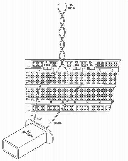
Figure 2-4. A circuit using the simulated "open" resistor.
Step 6. In Step 3 of this experiment, you found that there was no voltage drop across resistor R4. Notice that one end of R3 and one end of R4 connect to the negative terminal of the battery. Thus, the ends of these two resistors are at the same potential. Connect the black lead of your DMM to the end of R3 that is connected to the negative terminal of the battery. This connection also connects the black lead from the DMM to one end of R4.
Touch the red lead of the meter to the free end of R4. Once again, you should get a 0 V reading. Now connect the red lead to the end of R3 that is connected to R2. Make a mental note of the voltage reading. Leaving the red lead still connected to the junction of R2 and R3, connect the black meter lead to the free end of R4 and observe what happens. You should measure the same voltage. Disconnect the battery from the circuit.
This experiment shows that there is no voltage drop across R4, but there is continuity through it. If there had been no continuity, with the black lead connected to the free end of R4, you would have measured 0 V at the junction of R2 and R3.
Results:
This experiment demonstrates four important facts:
1. If current flows through a circuit, there will be a voltage drop across all parts not shorted in the circuit.
2. If one part in a complete circuit has no voltage drop across it, but there are voltage drops across all other parts, the part with no voltage drop is shorted. The short may be in the part itself or in some other parallel part.
3. If in a circuit that should be complete, you find full source voltage across one part and no voltage across the other part, the part with full source voltage across it is open.
4. If there is no voltage drop across a part, but one lead of the part connects to an operating circuit, both ends of the part will be at the same potential with respect to all other parts in the circuit.
-----------
Experiment 3: Voltage Polarity Introduction
Many of the expressions used in electronics servicing do not make sense to beginners until they are used in practical work. One expression that often causes confusion is positive or negative with respect to. This expression means that a point in a circuit is at a positive or negative potential compared to the potential at some other point in the circuit. For example, we may say that the drain of a field-effect transistor is 10 V positive.
This statement has no real meaning because a point by itself cannot have a voltage.
Voltage is defined as a potential difference between two points. Thus, when we say that there are 10 V at the drain of an FET, we mean that there is a potential difference of 10 V between the drain and a reference point.
Using Figure 3-1, let's suppose that the source of the FET is the reference point.
Thus, you can say that the drain is positive with respect to the source. If the drain is your reference point, then you would label the source as negative with respect to the drain.
At the same time, the gate is negative with respect to the source, and the source is positive with respect to the gate. Thus, depending on the reference points we select, the source can be seen as positive or negative.
In this experiment you will use resistors and a 9 V battery supply to determine polarity.
Another term that often causes confusion is ground. In most circuits, ground is simply a common reference point. Thus, in Figure 3-1, we say that the drain is positive with respect to ground. Schematic symbols used for ground connections are shown in Figure 3-2.
Very often, the metal chassis provides an electrical return path back to one side (usually the negative side) of the power supply. In this case, any one of the ground symbols might be used. An automobile is a good example of a chassis ground system. In most cars, all wiring is at some positive level with respect to the chassis.
An earth ground also provides a common return path back to one side of the power supply. In addition, it provides a degree of protection from shock hazards if the equipment is defective. Polarized plugs often are used to ensure the proper connection of earth-grounded equipment. A common tie point is like a chassis ground, except that terminal lugs are used in place of a metal chassis. If a metal chassis is used, only certain areas serve as return paths.
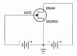
Figure 3-1. A field-effect transistor with batteries for drain-source
and gate-source biasing.
Materials Needed
To perform this experiment, in addition to the 9 volt battery, the breadboard socket, and your DMM, you will need the following:
1-1-
1- 2.2k resistor
4.7k resistor
10k resistor
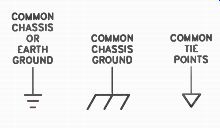
Figure 3-2. Schematic symbols for ground.
Procedure
For this experiment, you will construct the circuit shown in Figure 3-3. An illustration of this circuit is shown in Figure 3-4, on the next page. For convenience, we have numbered the junction of R1 and the negative lead from the battery as Terminal 1, the junction of R1 and R2 as Terminal 2, and so on.
We've also shown the negative terminal of the battery in Figure 3-4 going to ground. In an actual circuit, this might be a connection to the metal chassis or to the foil around the perimeter of a PC board.
In this experiment, the black lead from your DMM will be connected to Terminal 3, the junction of the 4.7k and 10k resistors (R2 and R3). Turn the range switch on the DMM to the 20 V DC range and proceed with the following steps.
Step 1. With the black lead from the DMM on Terminal 3, touch the red lead to Terminal 1. Record the polarity and the voltage in Table 3-1.
Step 2. With the black lead from the DMM still on Terminal 3, touch the red lead to Terminal 2. Record the polarity and voltage in Table 3-1.
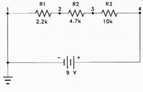
Figure 3-3. The circuit for Experiment 3.

Figure 3-4. An illustration of the circuit for Experiment 3.
Step 3. With the black lead still on Terminal 3, touch the red lead to Terminal 4. Re cord the polarity and voltage in Table 3-1.
Step 4. You already know the voltage and polarity of Terminal 1 with respect to Terminal 3. You determined these values in Step 1 of the experiment. To test your understanding of this subject, fill in the following statement. Perform whatever measurements are necessary in order to complete the statement.
Your response to this statement will help you to answer one of the exam questions at the end of this manual.
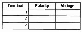
Table 3-1. Record your results for Experiment 3 here.
The voltage on Terminal 3 is with respect to Terminal 1, and (the same as, greater than, or less than) the voltage measured in Step 1.
Step 5. When you are finished, turn off the DMM and unplug the battery from the bread board socket.
Results
In Steps 1 and 2, you should have discovered that the voltages on Terminals 1 and 2 were negative with respect to Terminal 3. Your meter should have indicated a negative (-) sign in front of the voltage reading. The meter has built-in auto polarity. Thus, it automatically indicates whether the voltage being measured is positive or negative with respect to the common terminal.
In Steps 3 and 4, you should have discovered that the voltage on terminal 4 was positive with respect to Terminal 3. Depending on your meter, this is indicated by the absence of any sign or by a positive (+) sign ahead of the voltage reading.
The auto polarity feature of your DMM is one of the conveniences found in this type of meter. In some voltmeters, however, you will have to reverse the leads or change the position of a switch when taking negative voltage measurements.
In Step 4, you determined the voltage and polarity of Terminal 3 with respect to Terminal 1. To do this, you simply touched the black lead of the DMM to Terminal 1 and the red lead to Terminal 3. Voltages are measured with respect to the black (common) lead of your meter.
-----------------
Experiment 4: Measuring Voltage to Determine Current
Introduction Ohm's Law tells us that current in amperes is equal to the voltage in volts, divided by the resistance in ohms. Therefore, if we measure the voltage drop across a known resistor, we can accurately determine the current through it by dividing the voltage by the resistance.
In this experiment, you will see that you can determine the current flowing in a circuit by measuring the voltage across any known resistor and by applying Ohm's Law. You will also see how you can use the voltmeter scale to indicate current directly in milliamps if there is a 1-k resistor in the circuit.
Materials Needed
For this experiment, you will need your DMM, breadboarding socket, battery with clip, and the following resistors: 2 1-k resistors 1 4.7k resistor
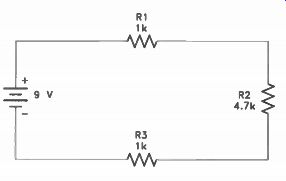
Figure 4-1. A schematic diagram of the circuit for Experiment 4.

Figure 4-2. An illustration of the circuit for Experiment 4.
Procedure
Step 1. Build the circuit shown in Figure 4-1. The diagram for this circuit is shown in Figure 4-2, on the next page. Notice the polarity of the battery. Also, the red meter probe should be reconnected to the V input jack.
Set your DMM selector switch to the 20 V range.
Step 2. Measure the voltage across R1 by connecting the red lead from your DMM to the end of the resistor connected to the positive terminal of the battery. Connect the black lead of your DMM to the other end of R1.
Record the voltage reading in Table 4-1.
Figure 4-2. An illustration of the circuit for Experiment 4.
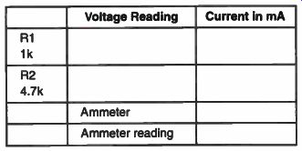
Table 4-1. Record your results for Experiment 4 here.
Now, to find the current, we use Ohm's Law, which tells us that the current in amperes is equal to the voltage in volts di vided by the resistance in ohms, or I = E/R. By substituting 1,000 for R and the voltage that you have just measured and recorded for E, you can find the current in amps. To change the answer to milliamps, multiply by 1,000 (or simply move the decimal point three places to the right). For example, let's say that the source voltage was 9 V and that we measured 1.43 V across R1. Using this figure, we get:
I= E/R 1.43 - 0.00143 amp 1,000
To change this to milliamps, multiply it by 1,000. This gives us:
0.0014 x 1,000 = 1.43 milliamps
Notice that to perform this operation we simply had to move the decimal point three places to the right.
Now, determine the current through the 1-k resistor from your experimental results.
Record your current in Table 4-1.
Step 3. Measure the voltage across R2 by connecting the DMM across it. Switch the meter to a lower range to get the most accurate measurement. Record the reading in Table 4-1.
Determine the current through R2 just as you did for R1 in Step 1. This time, substitute 4.7k for R in the formula and substitute the second voltage measurement for E. Re cord the current reading in Table 4-1, after multiplying the answer by 1,000 to change amps to milliamps.
You know that the current is the same in all parts of a series circuit. Therefore, the current determined in Step 3 should be the same as that obtained in Step 2. However, there may be some small variation in your results due to parts tolerances. The resistors used all have a 5% tolerance so the actual value may not be exactly the value indicated.
Step 4. In this step, you will use the DMM to measure the current flow in the circuit to see how close you come to the calculated value. Set your DMM to the 20 mA current range. Unplug the red lead from the V jack and plug it into the A jack. Unplug the negative lead from the battery and connect it to the black lead from the DMM. Connect the red lead to the end of R3, which was formerly connected to the negative lead of the battery This connection puts the meter in the circuit so that it can measure the actual current flow in the circuit. Record the measured value in Table 4-1. You should find that it agrees very closely with the calculated values obtained in Steps 2 and 3.
Step 5. After you've completed this step, move the red lead from jack A on the DMM back to jack V again. Turn your DMM to the OFF position.
Results
Now, let us compare your results for Steps 1, 2, and 3. The three current values should be approximately the same. Actually, the current is exactly the same anywhere in the circuit, but because of parts tolerances, your values probably show slight differences.
When we performed this experiment, the actual measured and calculated values came within 0.04 milliamps. This is a variation of only 40 microamps.
Notice the voltage value that you measured across the 1 k resistor (R1) and the current that you calculated for R1. The voltage across R1 and the current in milliamperes flowing through it should be the same because you di vided the voltage by 1,000 to find the current and then multiplied by 1,000 to change it to milliamps. In other words, when the resistance equals 1,000 ohms, the value of the voltage across it in volts is equal to the value of the current through it in milliamps. Thus, you can read the current directly on the volt meter scale if you are measuring across a I k resistor. If the voltmeter indicates 0.2 V, you have 0.2 mA of current. If it indicates 1.5 V, you have 1.5 mA of current, and so on.
While your DMM can measure current directly, you do have to open the circuit and put the meter in series with the circuit. Generally, this involves unsoldering a lead or a connection. If there happens to be a 1-k resistor in the circuit, you can simply measure the voltage across the resistor to determine the current. Thus, you will save the time needed to unsolder a part, take the reading, and re-solder the part.
Technicians seldom take current measurements or use Ohm's Law to calculate the current in the circuit. The circuit current values are not given for most electronic equipment.
However, the voltage values are generally given. If the correct voltage appears across the part, you can assume that the current is correct for that circuit. As far as the current is concerned, the technician is interested in only three possibilities. These are:
1. Is the current normal?
2. Is the current too high?
3. Is the current too low?
Voltage measurements can give an indication to all three answers without the use of Ohm's Law or the necessity of unsoldering and re-soldering connections. The technician usually does not care about the actual value of the current, but rather whether it is normal.
------------------
Experiment 5: Series Voltage Dividers
Introduction
As you have seen in the preceding experiments, if any resistance in a series circuit has changed in value, the voltage across each resistor will change. In some circuits, however, we want the voltage to remain fairly stable even when the resistance changes.
As you have learned previously, when a large resistor and a small resistor are in parallel, the combined resistance is approximately that of the small resistor. This means that even if the larger resistance varies some what, it will still be much higher than the smaller resistance. Thus, the combined resistance will remain essentially unchanged. This important fact can be put to good use when we want to stabilize the voltage across a load in which resistance varies.
For example, an amplifier is similar to a resistance connected across a power source. It converts a portion of the power supply voltage to a useful output signal. If the amplifier has to produce a higher output signal, it consumes more power from the power supply.
The power supply sees this increased demand as a decrease in load resistance. If the power supply is properly designed, it will maintain a constant voltage despite the varying load resistance.
In this experiment, you will build a circuit in which the load resistance can be varied and in which the load requires considerably less voltage than the source voltage of 9 volts.
You will see how the voltage across the load changes when the load resistance is changed.
Then, you will change the circuit so that the effects of variation in load resistance are reduced to a minimum.
As a technician, you may not be particularly interested in being able to design voltage dividers, but you should certainly know how they work. If you find that a particular circuit is not operating satisfactorily, you must rely on your voltage measurements to tell you what might have happened in the circuit. A knowledge of how voltage dividers operate will go a long way in helping you find the source of the trouble.
Materials Needed
Gather the battery with clip, your DMM, and the breadboarding socket. You will also need the following parts: 1 1-k resistor 1 4.7k resistor 1 10k resistor 1 10k trim potentiometer Hook-up wire Procedure
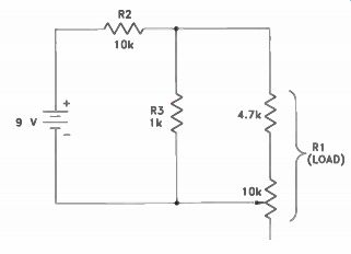
Figure 5-1. A schematic of the circuit for Step 1.
Step 1. Build the circuit shown in Figure 5-1. A pictorial layout of this circuit is shown in Figure 5-2, on the next page. Use the jumper cables supplied with this kit so that you can clip both leads of the meter to the circuit under test. Also make sure that the red test lead of your DMM is connected to the V jack. You are now ready to see how the circuit works.
Step 2. Measure the load voltage in Figure 5-1 by clipping the black lead from the DMM to the negative lead of the battery and the red lead to the junction of the 4.7k resistor and the 10k resistor (R2). The meter is now connected across the 4.7k resistor and part of the 10k potentiometer. These two parts make up the load resistor, R1, in Figure 5-1.
With a small screwdriver, adjust the potentiometer so that the meter reads 0.8 volts. We will consider this position to be the normal resistance of R 1. Now, turn the potentiometer fully counterclockwise. This increases the resistance of R1 and thereby increases the voltage across it. From the perspective of the power source, however, the higher load resistance appears to be a smaller load since it draws less current. Now record the voltage across the load at this time in the space labeled Voltage with Minimum Load in Step 2 of Table 5-1, on the next page.
Now, rotate the potentiometer fully clock wise, reducing the resistance of the variable resistor to practically 0. The resistance of R1 now consists of only the 4.7k resistor. This decreased resistance appears to be a larger load, from the perspective of the power source, because the circuit now draws more current. Note the meter reading and record it in the space provided for Voltage with Maxi mum Load in Step 2 of Table 5-1.
Step 3. Remove the 1-k resistor as shown in Figure 5-3, on the next page. The load is still made up of the combination of the 4.7k resistor and part of the potentiometer. Adjust the potentiometer fully counterclockwise.
Note the voltage reading and record it as the Voltage with Minimum Load for Step 3 in Table 5-1.
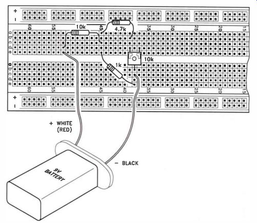
Figure 5-2. Layout of the circuit for Step 1.
Next, turn the potentiometer fully clock wise to reduce the value of R1. Record the reading as the Voltage with Maximum Load in Table 5-1. When you are finished with the experiment, unplug one lead of the battery to open the circuit and conserve battery life.
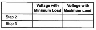
Table 5-1. Record your results for Experiment 5 here.
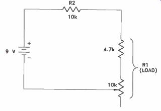
Figure 5-3. A schematic of the circuit for Step 2.
Results
Look over the figures you have recorded in Table 5-1 and compare the two sets of readings. In Step 2, there should be less of a difference between the maximum and mini mum voltages than in Step 3.
In many voltage dividers, the source voltage divides between the circuit parts. The voltage across a part is proportional to its resistance. If two parts have equal resistances, the source voltage will divide equally between them. Both will have the same voltage drop. If one part is variable, then it will have more than half of the voltage across it some of the time and it will have less than half the rest of the time.
In Step 1, you installed what is commonly called a bleeder resistor. This time, the voltage changes were much smaller. When two resistors are in parallel, the combined resistance is less than the smallest resistor. The combined resistance of R1 and the 1k bleeder resistor was between 780 S1 and 982 S2 depending on the potentiometer setting. In other words, when you added the bleeder resistor, changes in load resistance were substantially reduced. Therefore, load voltage was nearly the same (but much lower), regardless of load resistance variations.
In Step 3, you removed the bleeder resistor. With the potentiometer turned counter clockwise, the total load resistance was about 14.7 kilohms. This is nearly 1 1/2 times the resistance of R2. Thus, more than half the source voltage was dropped across R1. With the potentiometer turned fully counterclock wise, the total load resistance was only 4.7k, making R1 less than half the resistance of R2. Thus, most of the source voltage was dropped across R2.
In your work, be on the lookout for bleeder resistors. They can fail or change in value just like any other parts. You must take them into consideration when you diagnose a circuit where the components are in parallel with other electronic parts.
------------------
Experiment 6: Electrical Power
Introduction In this experiment, we will discuss the term power, and how it is determined in an electronic circuit. Power, whether it is electrical or mechanical, is defined as the rate at which work is being done. Work is done whenever a force causes motion to occur.
When mechanical force is exerted to lift or move, work is being done. However, when force is exerted without motion, such as when the force of a compressed spring is exerted between two stationary objects, work is not taking place.
With this in mind, we already know that voltage is the electrical force that causes current to flow in a closed circuit. When a voltage exists, but its force does not produce current flow, as in an open circuit, no work is being done. Work is accomplished when applied voltage causes electrons to move. The instantaneous rate at which this work is done is called the electrical power rate, and is measured in watts.
This unit measurement of electrical power is normally measured using a device called a wattmeter, illustrated in Figure 6-1. A watt meter combines both voltage and current, as shown in Figure 6-2, on the next page. Thus, we can conclude that power can be initially calculated using these two factors of voltage and current. Depending on the circuit quantities known, one of the following formulas can be used to determine power:
P=ExI P = IR P = E2/R
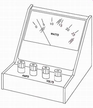
Figure 6-1. Wattmeter with a 25-watt range.
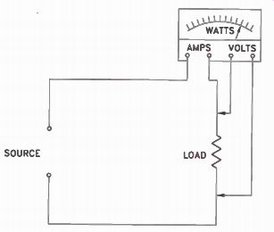
Figure 6-2. Wattmeter connections to measure power.
Where P is power in watts (W), E is in volts (V), I is in amperes (A), and R is in ohms (S). Electrical components are usually given a power rating. This rating, in watts, indicates the rate at which the device converts electrical energy into another form of energy such as heat, light, or motion. Light bulbs are the most common devices using this type of power rating. In other electrical devices this power rating indicates the maximum power the device is designed to use rather than the normal operating power.
Knowing how to determine the power of a given electrical configuration improves your overall competence as a technician. It might also help you to evaluate the performance of a defective circuit. For example, a power source could be loaded down if a circuit connected across it consumes too much power.
Knowing how to calculate power might help you locate the defective circuit.
Materials Needed
In this experiment, you will need the battery with clip, your DMM, the breadboard socket, and the following parts:
2 1-k resistors
1 2.2k resistor
1 4.7k resistor
Jumper leads
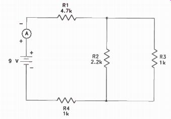
Figure 6-3. The circuit for Experiment 7.
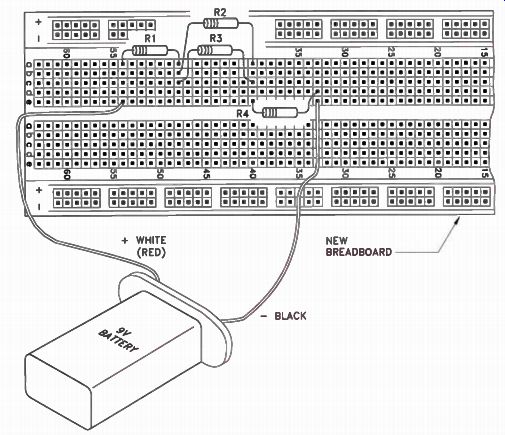
Figure 6-4. An illustration of the circuit for Experiment 6.
Procedure:
Wire Figure 6-3 on your breadboard socket. Refer to the diagram in Figure 6-4, on the next page, to make sure you have wired it correctly. Now you are ready to measure the power consumed by the circuit.
Step 1. Turn on your DMM by setting it to measure DC current. Start with the 20 mA/20 A range, since the amount of current flow in the circuit is unknown. Unplug the probe lead from the V input jack and connect it to the A input jack. This setup allows you to safely connect your DMM to the circuit as an ammeter.
Now, disconnect the positive lead of the 9-V battery from the breadboard socket and connect it to the positive lead of the DMM using one of the jumper leads. Connect the black lead to the free end of R 1. Measure the total current flow in the circuit and record your measurement in Table 6-1.
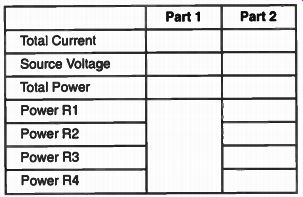
Table 6-1. Record your results for Experiment 6 here.
NOTE: If necessary, switch the DMM to a lower current range to get a more accurate reading. You will do this by positioning the selector switch to the 200-mA range, and moving the red lead of the DMM from the A jack to the mA jack. You can read even lower ranges now by simply placing your selector switch to the lower ranges.
Step 2. Next, you will measure the loaded source voltage. First disconnect the meter and reconnect the positive lead of the battery to R1. Set your DMM to the 20 V DC range.
Don't forget to unplug the red probe from the A or mA jack and connect it to the V jack.
Measure the loaded source voltage by connecting the black lead to the negative battery terminal and the red lead to the positive battery terminal. Record your measurement in Table 6-1.
You can now calculate total power consumption by multiplying the total circuit current by the loaded source voltage. If your current is in milliamps, you'll have to convert it to amps. Thus, if you measured 2.5 mA, divide this figure by 1,000 to convert it to amps. Record your results in Table 6-1 for total power under Part 1.
Step 3. To determine the power consumed by individual parts, you will need to measure the voltages across R1 and R4. Record your measurement in the margin of this page. Using the formula P = E x I, determine the power consumed by each of these resistors.
The value of I is the total current recorded in Table 6-1. Record your answers in Table 6-1 under Part 2.
Step 4. Next, you will determine the power used by resistors R2 and R3. The same voltage is dropped across both R2 and R3 because they are wired in parallel. However, the current is divided between them. Having determined the voltage, use the formula P = E2/R to find the power consumption for each resistor. Re cord your answers in Table 6-1 under Part 2.
Step 5. Add the power used by the individual parts in the circuit. Record your answer in Table 6-1 as the Total Power under Part 2.
Compare the Total Power for under Part 1 in Table 6-1 with the Total Power for Part 2. Except for a small difference, due to the parts tolerances, the results should be nearly equal.
Results
In this experiment, you calculated electrical power. You saw that power is determined by multiplying voltage by current. Total circuit power can also be determined by adding the power used by individual parts.
Technicians need to also understand that power is dissipated or converted to other forms of energy. Consequently, the fuse of a circuit responds to heat, a by-product of the power converted, by melting if the current flow exceeds the predetermined level. Some electrical parts are rated (in watts) according to their ability to dissipate heat.
----------------------
Preparing for Experiments 7-9
Ohmmeter Operation
In servicing electronic equipment, the technician usually relies on voltage and resistance measurements. Often, you will not be able to take voltage measurements, because a defect in the circuit overloads a fuse as soon as the equipment is turned on. Under these circum stances, the technician must rely on resistance measurements to locate the problem.
To use the ohmmeter section of your DMM, the black lead should be in the COM jack and the red lead should be in the V jack.
The switch is rotated through one of the six positions. You will learn how to properly select the correct position as part of the following experiments.
In taking resistance measurements, the equipment MUST be turned off. As a matter of fact, it is a good idea to unplug the equipment from the power line or disconnect the batteries if the equipment is battery operated.
This precaution will prevent accidental dam age to the DMM. If you try to take resistance measurements with the power turned on, the resistance measurements may be inaccurate, and you run the risk of damaging the DMM.
How Your Ohmmeter Works
Your DMM is primarily a voltage-measuring device. It does not measure the resistance of a part directly. The DMM contains six precision resistors that are used for resistance measurements. A different resistor is switched in for each range. In the 200-ohm range, a precision 200-ohm resistor is used internally.
In the 2k range, a precision 2k resistor is used.
When you take a resistance measurement, a small current flows through the precision resistor inside the meter and through the resistor under test. This flow produces a voltage across the resistor that the DMM measures and converts into a resistance reading.
Setting the Range Switch
As a general note, the objective in setting the range switch is to set the switch to the position that gives you the most significant reading. The maximum resistance that can be measured on each of the ranges is shown in the top row in Table 7-1. If you try to measure a resistance at too low a range, you will get an overload indication on the meter display. This reading tells you that the resistance is too high to be measured at that range. If you use too high a range when measuring a resistance, the meter will not give you the most accurate reading that it is capable of giving.
For example, suppose you have a 47 ohm resistor, and you want to check its exact resistance. Remember that resistors have a tolerance and that a 47 ohm resistor, having a tolerance of 10%, could have a resistance any where between 42.3 1 and 51.7 ohm and still be within tolerance. Because this resistance is less than 200 ohm , you would use the 200 ohm range to check the resistance.
In checking the resistance of a 47-ohm resistor in a lab, the two digits displayed on the left indicate 47. The digit on the right continually changes, sometimes displaying a 1, some times a 2, and sometimes a 3. This indicates that the resistance of the resistor is a little over 47 ohm. If we switch the range switch to the 2k position, the meter will display 0.047.
If we switch to the 20k range, we'll get a reading of 0.04 or 0.05. If we move the switch to the 200k range, we'll get a reading of 0.00. It is obvious from this that the 200 ohm range pro vided us with the most accurate reading. Now it is your turn to get some practical experience measuring the resistance of resistors.
Table 7-1. Record the reading on each range for the resistors listed and the range that gives the best reading.
------------------
Experiment 7: Using an Ohmmeter
Introduction
In checking the resistance of parts with an ohmmeter, there are three important rules to bear in mind:
Make sure the equipment that is being tested is turned off. If power is supplied from a power line, it is usually a good idea to remove the power line plug from the wall socket. If the equipment is battery operated, all batteries should be disconnected.
Use the correct range of the ohmmeter. As you will see, if you use the wrong range, the ohmmeter may indicate that a good part is open or shorted.
Keep your fingers off the part being tested when measuring high resistances. The resistance of your body can affect the result of your measurements. On low resistances, however, it does not matter. Do not touch the probes when measuring iron core devices, such as transformers or chokes, because you may receive a shock.
As you continue working with your ohm meter, you will learn other valuable tricks of the trade that will enable you to get the greatest use from the ohmmeter section of your DMM.
Materials Needed:
In this experiment, in addition to your DMM, you'll need the following resistors:
1-1-1- 1-1-1- 1-1-1-
1-k resistor
2.2k resistor
4.7k resistor
10k resistor
100k resistor
470k resistor
1M resistor
2M resistor
10M resistor
Procedure:
Step 1. Connect the ohmmeter leads to the 10M resistor and rotate the switch to the 20M position. You should get a reading a little above or below 10 megohms. Now touch the two ohmmeter leads with your fingers, and you will see that the reading drops. The resistance of your body is now in parallel with the 10M resistor, and thus reduces the resistance reading.
Step 2. Disconnect your ohmmeter from the 10M resistor and connect it across a 10k resistor. Now, starting with the 200 ohm range, note the reading on the DMM. Switch to the 2k and then the 20k, 200k, 2M, and 20M ranges. You should discover that on ranges below 20k, the DMM display indicated an overload. On the 20k range, you received a reading close to 10.00 kilohms. On the 200k, 2M, and 20M range, you got readings with fewer digits. Thus, the 20k range gave you the most accurate reading.
Step 3. Measure the resistance of each resistor listed in Table 7-1. Measure the resistance on each ohmmeter range.
Then, indicate the range that gave the most accurate reading. Record your results in Table 7-1.
Results:
In this experiment, you learned that you must choose a suitable ohmmeter range. The wrong range may indicate a fault when the resistor is actually good. Additionally, the appropriate range also gives you the most accurate reading for the resistor being measured.
----------------
Experiment 8: Circuit Continuity
Introduction:
You have seen in earlier experiments how circuit continuity can be checked with a volt meter. Also, you have learned that when continuity is intact, the circuit is able to carry current. While parts may have shorted or changed in value, these conditions do not affect the ability of the circuit to carry current.
If the circuit has continuity it simply means that the circuit does not have an open.
Most technicians prefer using the ohm meter for continuity testing, because it can easily be shifted to various points in the circuit to measure the actual resistance. Al though the ohmmeter can display the approximate sum of the resistances, it is not designed to measure the total resistance of the circuit while making continuity checks.
The true purpose of the ohmmeter is to show that the circuit is complete.
When making continuity measurements, technicians seldom bother to determine the actual resistance in the circuit. They simply check to see that there is a reading that shows continuity. When making continuity tests with your DMM, set the range switch to the 20M position. Otherwise, if you are checking a high-resistance circuit, you may get an overload reading that may lead you to believe that the circuit is open.
In this experiment, you will demonstrate that in a circuit containing both large and small resistances, a small resistor could be shorted without materially affecting the over all resistance measurement. To find such a short requires a check of the individual resistors. Do this type of check when the symptoms of the circuit indicate that there are possible problems causing the circuit to fault out.
Materials Needed
In this experiment, you will need your DMM, the breadboarding socket, the dummy resistor that you used in Experiment 2, and the following resistors:
1-1-1- 1-1-1-
1-k resistor
2.2k resistor
10k resistor
100k resistor
1M resistor
10M resistor
Procedure
You will make a voltage divider using five resistors in series and check the continuity.
Using your breadboarding socket, construct the voltage divider shown in Figure 8-1 and Figure 8-2, on the next page. By now, you should be able to build simple circuits with out the aid of a pictorial diagram.
Step 1. Measure the value of each resistor in the divider and record the resistance in ohms in the spaces provided for Step 1 in Table 8-1, on the next page. Now, add up the values of all five resistors and record this sum as the total resistance in the space provided.
Step 2. Connect one lead of your DMM to Terminal A and the other lead to Terminal B. Adjust the range switch to give a reasonable indication and record the value in Table 8-1.
Your reading should be approximately the same as the sum of the individual resistance measurements.
Step 3. To simulate a short across resistors R4 and R5, take a short piece of wire and connect it between Terminals B and D. With the DMM still connected to Terminals A and B, record your reading for Step 3 in Table 8-1. The value you record should be almost the same as that obtained in Step 2, showing that the two resistors could be completely shorted without materially affecting the ohmmeter measurement.
Step 4. Remove the 1-k resistor (R4) from the circuit and replace it with the 2.2k resistor. A change in resistance value from 1,000 ohm to 2,200 ohm is apparent when you check each individual resistor. However, see how it affects the total resistance by measuring the resistance from A to B and record your results in Table 8-1.
Step 5. Remove the 2.2k resistor and in its place substitute the simulated open resistor you made in Experiment 2. Now, measure the resistance between Terminals A and B. The meter will give an overload reading, indicating that the resistance between Terminals A and B is greater than 20 megohms. This certainly indicates that the circuit was open, since the original resistance was approximately 11 megohms.
Step 6. To find the open part in the voltage divider consisting of R1, R2, R3, the open resistor, and R5, connect the black lead from the ohmmeter to Terminal A. With the range switch in the 20M position, touch the red lead to Terminal E You should get a reading of about 10 megohms. Now, move the red lead to Terminal E. You should get a reading of about 11M, indicating continuity between Points A and E. Now move the red lead to Point D. Again, you should get a reading indicating continuity between Points A and D. Now move the red lead to Point C. You should get an overload indication that pinpoints the open circuit as being located between Terminals C and D.
Figure 8-1. The circuit for Experiment 8.
Figure 8-2. An illustration of the circuit for Experiment 8.
Results In this experiment, you saw that continuity can be checked with an ohmmeter. You saw that you can reduce the resistance of the divider in Figure 8-1 by completely shorting out R4 and R5 without appreciably changing the measured total resistance. Therefore, to check the condition of the individual resistors in a circuit having a high resistance, you must connect the ohmmeter directly across each resistor in question.
You also saw that an increase in resistance in one of the low-resistance parts will have no apparent effect on the total measured resistance.
These are key points to remember when troubleshooting electronic equipment. Make continuity tests when you suspect that a circuit is open, but remember that this does not show the value of the individual parts.
Table 8-1. Record your results for Experiment 8 here.
---------------
Experiment 9: Parallel Resistance
Introduction
You already know that electronic parts connected in parallel have a combined resistance lower than that of the smallest resistance of the group. However, as a service technician, you may want to know what the exact combined resistance should be. This enables you to measure the combined resistance and decide whether the parts are in good condition.
It is easy to decide what the combined resistance should be when parallel-connected parts have the same resistance. The rule is as follows:
The combined resistance of equal parts in parallel is equal to the resistance of one of the resistors divided by the number of resistors in the group.
Thus, if we connect three 1-k resistors in parallel, the combined resistance is 1,000 divided by 3, or 333 ohms. Three 3.3k resistors in parallel have a resistance of 1,000 ohms; two 22k resistors in parallel have a combined resistance of about 11,000 ohms.
Parallel-connected resistors are not always equal in value. When this is the case, the combined resistance, R, can be found by using the formula:
R - R1 x R2 R1 + R2
For example, if we have a 1-k resistor and a 3.3k resistor in parallel:
R _ 1,000 x 3,000 1,000 + 3,300 3,300,000 - 4,300 =- 767 ohms
It is helpful, but not imperative, that you be able to make these computations on a daily basis. As a busy technician, you may not always have the time to calculate them.
Instead, when you cannot readily tell the combined resistance at a glance, you may resort to simply unsoldering one end of each of the resistors and check the resistors individually.
If by chance you have the time to spare and find the calculations easy to work, then you can avoid the trouble of unsoldering a component to determine its condition and re solder the component into the circuit. It may be a good idea for you to invest in an inexpensive, hand-held calculator. With this additional tool, you can quickly work through these calculations.
When resistors do not have any shunting (parallel-connected) parts, the resistance value is checked by connecting the test leads directly across the resistor. With some meters, doing this can cause erratic readings if there are transistors or diodes in the circuit.
This is usually because the ohmmeter voltage is so high that the diode junction within the semiconductor may conduct and affect the measurement.
However, using the DMM issued in this kit, the voltage used in the ohmmeter section is so low that neither the diodes nor the transistors will conduct. This feature makes the DMM particularly useful in servicing solid state equipment.
In this experiment, you will connect resistors in parallel and measure their combined resistance. You will then check the measured value with the calculated resistance value to prove that the calculated value is correct.
Expect small variations between the calculated and measured values due to component tolerances.
Materials Needed
In this experiment, you will need your DMM, the breadboard socket, and the following resistors:
2 1-k resistors
1 2.2k resistor
1 10k resistor
1 100k resistor
1 10M resistor
Procedure
Table 9-1. Record your results for Experiment 9 here.
Step 1. Plug one of the 1-k resistors and a 2.2k resistor into the breadboard socket so that they are in parallel. Calculate the resistance with the formula:
R1 x R2 R+ = R1 + R2 1,100 x 2,200 R - 1,000 + 2,200 - 687.5 12
Measure the combined resistance. To do this, simply clip one lead from your DMM to each end of a resistor. Rotate the range switch until you get a suitable reading and record the measured value in Table 9-1.
Step 2. Remove the 2.2k resistor and re place it with a 10 k resistor. Calculate the resistance of the combination with the formula:
R1 x R2
R+ = R1 + R2
By substituting the values of the resistors, we have:
1,000 x 10,000 R - 1,000 + 10,000 - 909 ohms Now, measure the resistance of the parallel combination. Record this reading in Table 9-1.
Step 3. Following the same procedure, measure the combined resistance of the other parallel combinations listed in Table 9-1. In each case, calculate the values so that you can check the measured values.
Step 4. Build the series-parallel circuit shown in Figure 9-1. You should be able to do this without the aid of a pictorial diagram.
Before you measure the combined resistance, examine the circuit carefully and calculate in advance what the total resistance should be. Jot down what you think it is somewhere below the schematic diagram.
Step 5. Now connect one lead from the DMM to Terminal A and the other lead to Terminal B. Choose the appropriate ohmmeter range on your multimeter and read the resistance value. Compare this value with the value you calculated before taking the measurement within the circuit.
Figure 9-1. The circuit for Step 4 of Experiment 9.
Results
When you compared your measured values with the calculated values given in the chart, they should have been fairly close in most cases. However, because of the tolerances of the resistors, you may find that the readings differ somewhat in some cases.
When two resistors are in parallel and one is much larger, an accurate resistance check of the larger resistor cannot be performed until it is disconnected from the circuit. For example, when you measured the 10M and 100k resistors in parallel, their combined resistance should have been close to 100,000 ohms, or the resistance of the smaller resistor. Even when the 10M resistor was completely removed, the resistance remained close to the parallel value.
When there is only a slight difference in the value of the parallel resistors, or when one is disconnected or is defective, there will be a considerable change in the measured resistive value of the parallel configuration.
-------------------------
Experiment 10: Charging and Discharging Capacitors
Introduction
As you have learned, a capacitor is an electronic component that has the ability to store an electrical charge. In most circuits, capacitors charge and discharge constantly according to dynamic circuit conditions. Rates of capacitive charge and discharge are dependent upon the circuit resistance. The time (in seconds) required for a capacitor to charge to 63% of the applied voltage is equal to the resistance value (in megohms) multiplied by the capacitance value (in microfarads). This is known as the time constant of the circuit, and it is typically expressed as TC = R x C. Materials Needed For this experiment, you will need the breadboard socket and your DMM in addition to the following parts:
1 9-volt battery with clips
1 10k resistor
1 100k resistor
2 10 microF electrolytic capacitors
If you need to do so, install the battery clips on the batteries at this time.
Procedure Wire the circuit shown in Figure 10-1. Do not connect the negative battery lead until you are instructed to do so. Use a 10k resistor for R, set your meter to the 2 mA position, and move the red lead to the mA socket.
Figure 10-2, on the next page, shows one way to breadboard the circuit.
Figure 10-1. A DC voltage capacitor charging circuit.
Figure 10-2. One way to breadboard the connection for Experiment 10.
To get the 20pF capacitance shown in Figure 10-1, you'll have to connect two 10 uF electrolytic capacitors in parallel. When capacitors are connected in parallel, the total capacitance is the sum of the individual values. Remember that electrolytic capacitors should be installed with polarity positioned in the appropriate direction.
When you connect the 9-volt battery to the circuit, the voltage across the series connected resistor and capacitor will be 9 volts. The time it takes the capacitor to charge depends on the amount of resistance and capacitance in the circuit. If either the resistance or the capacitance is increased, the amount of time it takes to charge the capacitor will increase as well.
Step 1. When you're ready, touch the 9-volt battery black lead to the capacitor's negative lead. As soon as you do this, the meter will indicate a charging current. When the meter display changes to 000, the capacitor has become completely charged.
Step 2. To repeat the experiment, you'll have to discharge the capacitors. To observe the capacitive discharge current, simply unclip the red meter lead from its current position. Move the red lead to the negative lead of a capacitor. You should see the same indication on the meter as before. This shows the capacitors discharging through the resistor and the meter in the opposite direction of current flow. You can repeat Steps 1 and 2 several times to observe the action.
Step 3. Increase the amount of resistance in the circuit by replacing the 10k resistor with a 100k resistor. Repeat Step 1 and Step 2 of the experiment. Notice that the current displayed on the meter display indicates 000 more slowly than it did before in both the charging and discharging cycles.
Step 4. Remove one of the 10µF capacitors and repeat Step 1. Notice that the charging rate is faster with less capacitance in the circuit. Short the leads of the capacitors by touching the leads together. By doing this you will discharge the capacitors. Now, connect the capacitors in series to reduce the capacitance further. Electrolytic capacitors are connected in series, just like two batteries connect the positive lead of one capacitor to the negative lead of the other. The circuit should charge very quickly because it has less capacitance. (If you want to repeat this step, you will have to discharge the capacitors each time.)
Step 5. Disconnect the battery to turn the circuit off.
Results
In Steps 1 and 2 of this experiment, you proved that when power is applied to a capacitor, a high current initially flows and then decreases as the capacitor charges. As the current diminishes, the meter will eventually indicate zero. You also learned that a capacitive circuit discharges in the opposite direction. Lastly, you may have noticed that as long as the charge and discharge paths remained the same, the time for charging and discharging was equal.
In Steps 3 and 4, you saw that increasing the resistance in the circuit caused the time constant to increase. In this case, it should have taken 10 times as long for the capacitor to fully charge through the 100k resistor as it did through the 10k resistor. You also proved that capacitors connected in series have less capacitance than capacitors connected in parallel. Decreasing the capacitance also decreased the charge and discharge times. This is because the time constant was smaller. Similarly, increasing the capacitance in the circuit without changing the resistance increases the time constant.
-------------------
Experiment 11: Basic Coil Action
Introduction
A coil is an inductive device created by a looping turn of wire around a core. The conductor is usually copper wire. The core can be made of any material that affords a path for magnetic flux lines in a coil. The DC resistance of a coil is the same as the resistance of the wire itself meaning that the form of a coil doesn't change the conductor's DC characteristics. However, it does change the way the wire responds to alternating current (AC). Because a coil of wire can oppose the starting, stopping, or changing of current, it has the characteristic of inductance.
Recall that inductance is the characteristic of a coil that enables it to induce a voltage into itself. Winding wire in the form of a coil causes a significant increase in the inductance properties. Therefore, when inductance is increased the inductive reactance increases.
The opposition that the coil offers to alternating current is much greater than its opposition to direct current. This opposition to current flow is known as impedance.
You have already studied these properties in an earlier lesson. We suggest that if these factors sound vague to you, you may want to review the earlier lesson to refresh your memory concerning the impedance, reactance, and inductance properties of coils.
Materials Needed
For this experiment, you will need the breadboard socket, your DMM and the following parts: 2 9-volt batteries with clips 1 1-k resistor 2 Red light-emitting diodes 1 Choke coil
Figure 11-1. Circuit connection to demonstrate counter electromotive force (CEMF).
Procedure
A full study of inductance, inductive reactance, and many other aspects of inductors (coils) would normally require weeks of laboratory time. Therefore, this experiment will focus on the basic properties of coils. In this experiment, you'll construct a simple inductive circuit and use light emitting diodes (LEDs) to observe the voltage changes in the circuit.
You will want to begin this experiment by constructing the circuit shown in Figure 11-1 without the LEDs. To get the 18 V supply, you'll have to connect two 9-volt batteries in series aiding. Use the diagram in Figure 11-2 if you need help. Be sure to move the red lead of your DMM back to the V socket.
Figure 11-2. One way to connect components for coil demonstration.
Step 1. Connect the negative lead of the 18 V supply to the free end of the 1-k resistor and the positive lead to the free lead from the choke coil. Set your meter to the 20 V range and measure the voltage drops across the resistor and the coil. You should find that the DC voltage across the resistor is more than the DC voltage across the coil. Thus, the resistance of the coil is less than 1 kilohm. The coil's inductive properties will become evident as you connect the LEDs later in this experiment.
Step 2. Disconnect the battery red lead from the coil. Connect the LEDs across the 1-k resistor and the coil with the polarity, as shown in the schematic. An LED lights when a negative voltage is applied to the cathode and a positive voltage is applied to the anode.
Ensure that the components are installed into the circuit properly, review Figure 11-1 carefully.
The second LED (L2) should be connected with opposite polarity when compared to first LED (L1). Current should flow from the battery, through LED L1 and the 1-k resistor, through the coil, and back to the battery positive. Current should not flow through LED L2 at this point.
Step 3. Touch the battery red lead to the free end of the coil. Current in the circuit flows through L 1 and bypasses L2.
Step 4. Disconnect the red lead from the coil and carefully watch L2.
Step 5. Disconnect the battery.
Results When you initially connected power, LED L I turned on, indicating current flow in the circuit. LED L2 did not light because it does not conduct (it is reverse biased). When you disconnected the battery from the circuit, you saw that LED L2 lit very briefly. Can you ex plain this from what you know about coils and their properties? When you disconnected the battery, the circuit DC current stopped. The magnetic field surrounding the coil (induced by current flow) collapsed as circuit current stopped.
The collapsing magnetic field induces a voltage and current into the coil in the opposite direction of the battery current. The opposite polarity of the induced voltage is of the correct polarity to light L2. The induced voltage (sometimes called CEMF, or counter electro motive force) is of very brief duration, lasting only as long as the decreasing current is changing.
-------------------------
Experiment 12 : Transistor Operation
Introduction
The two types of bipolar transistors are the NPN and the PNP transistors. Both types are used in electronic circuits. For any transistor to operate, the emitter-base junction must be forward biased and the collector base junction must be reverse biased. Applying this requirement to the NPN transistor shown in Figure 12-1(A), this means that the base must be positive with respect to the emitter, and the collector must be positive with respect to the base.
Figure 12-1. (A) An NPN transistor can be represented as (B) two back-to-back diodes.
Figure 12-2. (A) A PNP transistor and (B) diode equivalent.
Figure 12-1(B) shows a two-diode representation of the NPN transistor. D1 represents the base-emitter junction, while D2
represents the collector-base junction. Figure 12-2 is similar to Figure 12-1, but it shows a PNP transistor symbol and its two-diode representation.
In this experiment, you are going to show that an NPN transistor can have a current gain when properly biased. That is, a small current in the input circuit can control a much higher current in the output circuit.
Also, you will learn how to measure voltages to determine if a transistor is saturated (conducting hard), cut off (not conducting), or biased for linear (Class A) operation.
A transistor is a solid-state device that amplifies by controlling the flow of current carriers through its semiconductor materials. The
basic idea of current flow within a transistor is that the amount of current flowing from emitter to collector is controlled by the base current. The base current is very small com pared to the collector current. Therefore, in creasing or decreasing the base current will cause a much larger collector current to increase or decrease. The total current flow in a transistor flows in the emitter circuit. Approximately 95% of the emitter current reaches the collector circuit, while the remaining 5% passes through the emitter-base circuit.
Materials Needed You will need your breadboard socket, 9 volt battery with clips, your DMM, and the following parts:
1-1-1- 1-1-1-
1-k resistor
2.2k resistor
4.7k resistor
10k resistor
10k trim potentiometer
NPN transistor (2N3904 or equivalent)
Figure 12-3. Schematic for the circuit for Experiment 12.
Figure 12-4. Lead identification for a typical transistor.
Figure 12-5. An illustration of the circuit for Experiment 12.
Procedure
Construct the circuit shown in Figure 12-3 on your breadboard.
Figure 12-4 identifies the leads of the transistor. As in an earlier experiment, the 18 V supply is produced by connecting two 9-volt batteries in series aiding. Figure 12-5, on the next page, shows an illustration of one way to wire this circuit.
Set your meter to 20 V DC and connect the black lead to ground. For this experiment, you will measure the output voltage directly from the collector of the transistor. The input voltage will be measured at the end of the 10k base resistor that connects to the center tap of the 10k potentiometer. Base voltage will be measured directly from the base of the transistor. In a moment, you'll see why the base voltage isn't necessarily the input voltage.
Step 1. Connect the battery and rotate the 10k potentiometer fully in the counterclock wise direction. Measure the output voltage on the collector and record the reading in Table 12-1, on the next page. Then, measure the base voltage and record this measurement in Table 12-1. Measure the input voltage as indicated above and record this voltage in Table 12-1, even if it's zero. Then, slowly adjust the potentiometer until you acquire a reading of 1 volt.
Step 2. With the input set to 1 V, measure the base voltage again. It should be about
0.7 V direct current. Record your results in Table 12-1. This means you have approximately 0.3 V dropped across the 10k resistor. Using Ohm's Law, it is easy to determine that you have approximately 30 microamps of current in the base circuit.
Step 3. After you record the DC voltage at the base, re-measure the output voltage and record it in Table 12-1. Now, turn the potentiometer completely clockwise and record the collector (output) voltage. Next, measure and record the input voltage once again. Then, measure and record the voltage on the base of the transistor.
Step 4. Adjust the 10k control for an input of 1 volt. Remember, for this experiment, the input is measured at the center tap of the control. Do not readjust the control after setting it.
Step 5. Now, measure the collector supply voltage and record this voltage in Table 12-2.
Table 12-1. Record your results for Step 1 here. Figure 12-2. Record your results for Step 2 here.
Then, measure and record the collector out put voltage. Subtract this voltage from the previous reading and enter your result as the voltage drop across the 1-k collector load resistor. To find the collector current, divide the voltage across the collector by the resistance and enter your results.
Step 6. Next, remove the 1 k load resistor and replace it with a 2.2k load resistor. The total resistance is now more than twice the original value. Again, measure the supply and output voltages and determine the voltage drop across the collector resistor. Then, calculate the collector current and record it in Table 12-2. When you are finished, disconnect the batteries from the circuit.
Results An NPN silicon transistor was used in Step 1. Until the bias pot was properly adjusted to produce the necessary base voltage, there was no current flow through the transistor. This was determined when you read the full supply voltage at the collector. The transistor was cut off (not conducting), and it appeared as an open circuit.
When the bias control was adjusted to pro duce 1 V DC at the 10k base resistor, you should have measured approximately 0.7 V DC at the base. You will always measure between 0.6 and 0.7 V across the emitter-base junction of a conducting silicon transistor.
With the proper bias voltage present, the transistor began conducting, and there was a voltage drop across the collector load resistor.
You should have measured about 12.3 V DC at the collector of the transistor. This indicates that the transistor is no longer cut off.
From this experiment, you have proved that a transistor must be biased before it will conduct. The emitter-base junction is for ward biased with a positive voltage at the base and the emitter grounded. A positive voltage at the base of an NPN transistor causes a reduction in the voltage at the collector. The collector was connected to a +18 V DC supply through a 1-k resistor. The base collector junction was therefore reverse biased.
When you increased the bias voltage to maximum, you found that the voltage across the emitter-junction remained essentially constant, while the voltage across the base resistor increased. This resulted in an increase in base current. This small change in base current was more than sufficient to saturate the transistor and cause the collector voltage to drop almost to zero.
A saturated transistor appears as a very low resistance, and it drops very little voltage. It has characteristics very similar to a turned-on switch. The majority of the voltage in this circuit is dropped across the collector resistor.
You also learned that once the transistor is saturated, further increase in base-emitter current will not affect the collector current. When a transistor is properly biased to operate as a linear (Class A) amplifier, the collector voltage will be approximately half of the supply voltage. In the circuit that used an 18 V DC supply, the collector voltage should be adjusted for approximately 9 V to allow a maximum positive and negative swing of an input signal without distortion.
Additionally, you learned that the size of the collector resistor did not greatly affect the collector current. From this experiment, you have determined that the base current, which you can vary by adjusting the control, actually controls the collector current; the transistor is a current-controlled device with a small base current (about 30 mA) controlling a large collector current (about 5.6 mA).
---------------------
251
Examination Questions
This is Examination Number 2332.
Make sure you print your name, student number, and examination number (Lesson No.) in the space provided on the Answer Form. Be sure to fill in the circles beneath your student number and examination number (Lesson No.). Reminder: A properly completed Answer Form allows us to evaluate your answers and speed the results and additional study material to you as soon as possible. Do not hold your Answer Forms to send several at one time. You may run out of study material if you do not send your answers for evaluation promptly.
1. If you measure the full source voltage across one of the components in a circuit and zero voltage across all the other components, then:
a. The component with full source voltage across it is shorted.
b. The component with full source voltage across it is open.
c. One of the components with no source voltage across it is open.
d. One of the components with no source voltage across it is shorted.
2. In a parallel circuit made up of two 1-k resistors, what happens to the total resistance if a 1M resistor is added in parallel with them? (Note: For accuracy, calculate the values instead of using the DMM)
a. It decreases slightly.
b. It decreases substantially.
c. It remains exactly the same.
d. It increases.
3. If the load resistance in the circuit used in Experiment 5 increases, the voltage drop across it will , indicating that the output current has
a. Increase, increased
b. Decrease, decreased
c. Increase, decreased
d. Decrease, increased
4. In the circuit shown below, the current leaving the parallel branch and flowing to the positive terminal of V is the current flowing through R1.
a. Usually greater than.
b. Considerably greater than.
c. Considerably less than.
d. Equal to.
----------252
5. What is the most practical and quickest way to determine total current in the circuit for Question 4?
a. Create an open in the circuit and then connect an ammeter.
b. Use Ohm's Law to calculate after measuring the voltage across R1.
c. Measure the voltage across R3.
d. Use Ohm's Law to calculate after measuring the voltage across R2.
6. Using the values recorded in Table 3-1, what is the voltage on Terminal 3 of Figure 3-3 with respect to Terminal 1?
a. Negative and equal to the voltage measured in Step 1.
b. Positive and equal to the voltage measured in Step 1.
c. Positive and much smaller than the voltage measured in Step 1.
d. Positive and much greater than the voltage measured in Step 1.
7. According to the information you recorded in Table 7-1, what ohmmeter range gave the most significant reading for the 2.2k resistor?
a. 2k.
b. 20k.
c. 200k.
d. 2M.
8. What resistance did you measure from the circuit shown in Figure 9-1?
a. Approximately 2,700 ohms.
b. Approximately 5,500 ohms.
c. Approximately 17,000 ohms.
d. Approximately 28,500 ohms.
9. What change in resistance would you expect between Terminals A and B of Figure 8-1 if resistors R3, R4, and R5 were shorted?
a. Increase more than 10 percent.
b. Decrease more than 10 percent.
c. Decrease less than 5 percent.
d. Increase 1 percent.
10. When you compared the base and collector currents of the conducting transistor in Experiment 12, you found that:
a. No current flowed in the circuit.
b. They were about equal.
c. The base current was slightly greater than the collector current.
d. The collector current was much greater than the base current.
--------------------------------------
NRI Graduates Say... "My NRI training really helped on the job. This gave me confidence and peace of mind, besides enabling me to tackle more challenging and profitable work.
I'd recommend NRI training, in fact I already have. The material is well presented, and explained in a way which anyone can understand.
The outstanding thing about my NRI training is the feeling that there were competent instructors I could call on when I ran into difficult lessons."
Frank J. Burke St. John's, Newfoundland Canada.