AMAZON multi-meters discounts AMAZON oscilloscope discounts
Table of Contents:
- Introduction
- Batteries
- Primary Batteries
- Secondary Cells
- Review Self-Test Questions
- Magnetism
- Permanent Magnets
- Electromagnets
- Review Self-Test Questions
- Generators
- Direct and Alternating Current
- A Simple Generator
- How Voltages Are Pictured
- DC Generators
- AC Values
- Review Self-Test Questions
- Answers to Self-Test Questions
- Lesson Questions
---------------
Lesson Objectives
In this lesson, you will:
• Study primary and secondary storage batteries as electrical power sources.
• Review magnetism and electromagnetism.
• Apply electronic principles to magnetic circuits that generate electric current.
• Learn how AC and DC power are generated.
• Learn the waveform characteristics of AC voltage and current.
------------
INTRODUCTION
There are two common methods of producing electricity. One method is by chemical action, the other uses mechanical action. Both techniques provide a primary source for electrical power.
The everyday application of chemical power generation is in the use of batteries of all kinds.
In this lesson you will study several types of batteries and explore how they work and how they are best applied. You will then learn how large amounts of electricity are produced by motor-driven generators and other mechanical systems.
BATTERIES
Two types of batteries are typically used in electronic applications: primary and secondary.
Primary batteries are composed of primary cells, which not be effectively recharged. An ordinary flashlight battery is an example of a primary battery. A flashlight battery is simply discarded when it wears out. In contrast, a second battery is made from rechargeable-cell, such as the storage batteries used in automobiles and the familiar nicad (nickel-cadmium) batteries used for children's toys and other small electronic products.
A battery produces electricity through a chemical reaction of two different materials; in this reaction, electrons transfer from one to the other. By intercepting the flow of electrons at some point, you can put them to work. The voltage and current produced by the two materials from which the battery is made are determined by the degree of reactivity they have with respect to oxygen, since the chemical action of batteries is what we call an "oxidation" reaction. The greater the reactivity between the two materials, the greater voltage and current potential they have.
Primary Batteries
Primary batteries are not rechargeable. The generation of electrical power through transfer of electrons in the battery material eventually uses up the battery. That is, the materials making up the battery stop reacting, and the battery is dead. This may seem to be a major drawback, but primary batteries may be more cost-effective than secondary batteries in certain applications, especially since they boast an ex tended shelf-life, holding a useful charge for several years, where rechargeable secondary cells will discharge in a relatively short period of time, with or without a load.
A simple electric cell consists of pieces of two different metals submerged in an acid solution.
The voltage produced by the cell depends on the metals used, as has been mentioned. For ex ample, zinc and copper produce a cell voltage of about 1.1 volts. Copper and silver increase the output level to 1.5 volts. In contrast, gold and manganese are quite reactive, and can generate a voltage as high as 3.7 volts. Of course, a battery with this relatively high voltage is not economically practical because of the high costs of gold and manganese.
Dry Cells. Dry cells are not really "dry." They are called dry cells because their chemical mix ture is in the form of a paste rather than a liquid.
The construction of an ordinary carbon and zinc dry cell battery is shown in Fig.1. Carbon-zinc cells are widely used for general-purpose batteries.
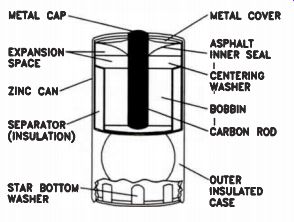
Figure 1. Principal parts of a typical carbon-zinc dry cell.
Zinc is one of the two reactive metals in the cell. Zinc metal plate formed into a can constitutes the anode. The zinc can also act as the container for the acid solution and the manganese compound. Zinc cans are usually enclosed in a thin steel jacket to increase durability and reduce the possibility of leakage, since pure zinc is structurally weak.
Inside the can is a separator made of paper or paste. It acts to physically and electrically isolate the positive and negative electrodes, while permitting electrolytic transmission in the acid electrolyte solution. Paste separators are made of electrolyte plus a gelling agent such as starch or flour. Paper separators provide superior separation and power-to-weight ratio. The paper is coated with a gelling agent and impregnated with electrolyte from the cathode material. Ordinary general-purpose dry cells use an electrolyte made of ammonium chloride, zinc chloride, and water. In heavy-duty cells, the electrolyte has a much higher percentage of zinc chloride.
Most of the material composing the cell is the cathode mix. This is the black mix, also known as the "bobbin." It is made of manganese dioxide, carbon black, and electrolyte. The carbon does two things: it holds the electrolyte in a semisolid state, and it increases the electrical conductivity of the mix. Some cells use a very pure form of manganese dioxide, known as EMD (Electrolytic Manganese Dioxide), in the black mix. They are more expensive, but the pure compound makes an extra heavy-duty cell.

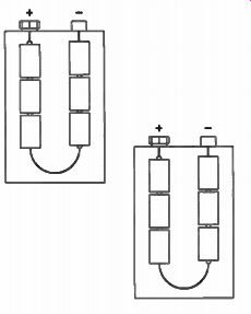
Figure 2. A 9 V transistor radio battery.
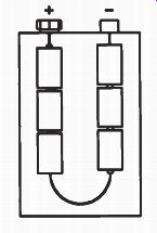
Figure 3. A drawing showing how the six cells are arranged in a 9 V
battery.
Although these cells are frequently called carbon-zinc batteries, carbon is not a part of the chemical reaction that produces electricity.
Carbon is not a metal; the active metals are zinc and manganese. A carbon rod inserted in the center of the black mix helps protect the mix from internally-generated heat, and is used as an electrode attachment point. The porous carbon rod also acts as a vent for hydrogen gas.
The no-load voltage developed by a carbon zinc cell is nominally 1.5 V, although an unused cell may measure as high as 1.6 volts. Figure 2 is a drawing of a 9 V transistor radio battery.
This battery is made up of six 1.5 V cells arranged as shown in Fig.3. The cells are connected in series; each provides a voltage of 1.5 V to give a total voltage of 9 volts.
Alkaline Cells. Alkaline cells get their name from the highly caustic base (potassium hydroxide) used in the electrolyte, rather than a slightly acidic one containing a salt such as ammonium- or zinc-chloride. An alkaline cell is similar to a carbon-zinc cell, but has significant differences, as Fig.4 illustrates (on the next page).
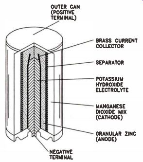
Figure 4. Principal parts of an alkaline cell.
The cathode material of an alkaline cell is EMD, the pure manganese dioxide sometimes used in carbon-zinc cells to improve performance. It is mixed with water, carbon, and some potassium-hydroxide electrolyte. Like a dry cell, the anode is zinc, but the zinc metal is a powder held in a steel jacket. The highly purified zinc powder is mixed with small amounts of mercury, forming an amalgam that greatly reduces hydrogen production in the cell. The separator is made of a porous woven, felted, or bonded material.
Alkaline cells have a no-load voltage of about 1.52 volts. Their performance exceeds that of carbon-zinc types. Alkaline cells have greater temperature tolerance, and their low current drain performance is better. However, alkalines are best where moderate to high currents are drawn for an extended time. Carbon-zinc and alkaline cells are both available in a wide range of packages and voltages. Although alkaline cells have (mostly) replaced carbon-zinc types, there are places where carbon-zinc gives better performance for price. Typically, where current drain is low but constant, and operating temperature is not extreme, carbon-zinc cells are more economical. However, they have a relatively short shelf life, so they are best suited to applications where they will be replaced regularly.
Alkaline cells can produce higher currents than carbon-zinc cells, and recover more quickly after heavy use. They are ideal for much of today's consumer-electronics equipment: cassette players, portable TVs, and radios. Electronic products can operate for several hours on alkaline cells, but would drain carbon-zinc batteries in 30 minutes.
Alkaline cells have a longer shelf life, and their output voltage decreases more slowly than carbon-zinc cells. You can extend the shelf life of carbon-zinc cells by refrigerating them to slow the chemical reactions that take place even when they are not being used. These reactions are at a much lower level in unused alkaline cells. Even with the benefit of refrigeration, however, carbon-zinc cells still have a much shorter shelf life than alkaline cells.
Low temperatures cause voltage output reductions in all types of batteries. Alkaline cells have a consistent output over a greater temperature range than do carbon-zinc cells. In temperatures below freezing, a carbon-zinc cell is incapable of delivering more than a fraction of its rated current, and is generally considered unusable. Alkaline cells have reduced output at low temperatures, but are still better than the best carbon-zinc cells.
Secondary Cells
The most desirable quality of secondary cells is their ability to be recharged. Lead-acid secondary cells, frequently called "storage" batteries, are used in automobiles, making them probably the best known example of a secondary cell.
There are several other designs for rechargeable batteries. Along with their operating characteristics, we will review the advantages and disadvantages of each.
Lead-Acid Batteries. This type of cell has two sets of internal plates. One set of plates is connected, or "bussed," together for the positive terminal; the other set of plates is bussed together and brought out at one point as the negative terminal. The set of positive plates is treated chemically to change it to an oxide of lead, the negative set is pure lead. They fit together as shown in Fig.5.
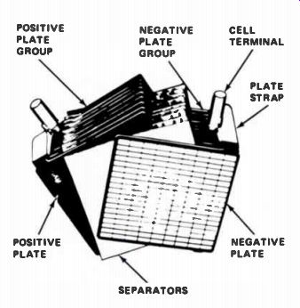
Figure 5. The construction of a storage battery.
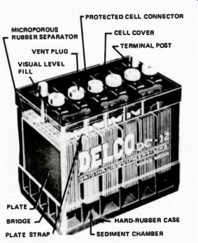
Figure 6. A 6-cell, 12 V battery.
Between the plates are sheets of insulating material called separators, made either of porous wood, perforated wood, or fiberglass. The separators keep the plates from touching, which would short-circuit and destroy the cell. Both sets of plates and separators are sealed into a container of sulphuric acid and water. This type of cell produces approximately 2 volts, plus or minus 10% depending upon conditions. Storage batteries used in modern automobiles are made of six cells connected in series so that the battery output voltage is 12 volts. A 6-cell battery is shown in Fig.6.
The lead-acid battery is charged by applying a voltage slightly higher than the battery voltage. The charger forces current through the battery, as shown on the next page in Fig.7. This current causes a chemical change in the battery, which restores the battery to essentially the same reactive chemical state it had before being used as a power source.
Notice the direction of current in Fig.7, as compared to Fig.8. When the battery is being charged, the current is forced through the battery in the opposite direction to which it flows when the battery is supplying current. In an automobile, the battery is connected to an alternator. As long as the car runs at a reasonable speed, the alternator both charges the battery and supplies operating current to the car.
Both small and large lead-acid batteries are available with a gelled electrolyte that allows them to be used in portable equipment without spilling. Lead-acid cells are also available in the form of sealed D-size cells. Lead-acid batteries are capable of sustaining very high rates of discharge. However, like most chemical reactions, the performance of lead-acid cells falls off at cold and very warm temperatures. They must also be kept well charged to achieve good performance over a long lifetime.
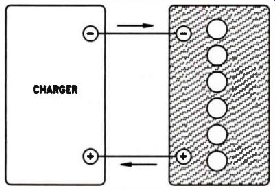
Figure 7. The direction in which current flows when a storage battery
is charged.
Lithium Cells. Until recently, lithium cells were not generally regarded as recharge-able devices. However, rechargeable lithium manganese oxide cells have made an appearance. They are intended primarily as replacements for nicad cells and large-value capacitors used in keeping memory circuits alive during equipment "off' periods. The internal construction of a flat lithium battery and a cylindrical lithium battery are shown in Fig.9(A) and 9(B), on the next page.
Lithium is an extremely reactive metal, which makes it an excellent component in energy cells.
Unfortunately, its high reactivity (it decomposes rapidly in water, for example) makes it difficult to work with. Many of these difficulties have been overcome, however, and lithium-based cells are now found in watches and calculators - wherever a trickle current is needed.
The output of a lithium cell is nominally 3 V; in some applications you can replace two 1.5 V carbon-zinc or alkaline cells with one lithium cell. A lithium battery with a 1.5 V output is also available. Lithium cells have an extremely long shelf life: 5, or even 10, years. Under conditions of low drain, their useful working life may also be five to seven years.
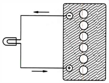
Figure 8. The direction current will flow when the battery is supplying
current.
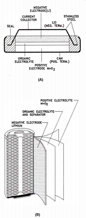
Figure 9. Lithium batteries. (A) Construction of an Li/MnO2 button cell.
(B) Construction of an Li/MnO2 cylindrical cell.
Nickel-Cadmium Cells. The internal details of a typical nickel-cadmium cell are similar to those of lithium cells. The active materials are nickel oxide, which forms the cell's positive plate, cadmium for the negative plate, and caustic potassium hydroxide electrolyte. Several manufacturing techniques are used, but typically, the positive and negative electrodes sandwich the separator in the middle. Those three layers are rolled up into a spiral package.
The separator may be nylon or polypropylene. A safety vent is provided to help prevent cell rupture from pressure buildup during charging.
The normal rate at which a nicad recharges is at one-tenth the rated output current. For ex ample, 60 mA is the correct charge current for a cell with a rating of 600 mAh (milliampere hours). The charging time should be about 14 to 16 hours. However, this is a nominal rate, and is dependent upon the cell design. Some quick charge cells can be recharged in four to six hours, and fast-charge devices can be charged at much higher currents in two hours or less. The true limitation on cell charging rate is a function of the temperature increase produced by the charging current, and the possibility of cell rupture or internal plate damage due to internal pressures.
Nickel-cadmium cells do not lose voltage out put at the same rate as carbon-zinc and alkaline cells. Fully charged, nicad no-load output voltage is about 1.4 V, which drops almost immediately to 1.25 V, and is then maintained until the charge is nearly exhausted. Nicads can provide very large amounts of current when needed, and perform consistently under conditions of continuous drain. They also have good power output under extremes of temperature.
Nickel-cadmium cells give lasting service when worked hard. In light use, they may develop a "memory" and eventually lose some of their capacity. However, recent developments in battery technology have made that much less of a problem. The charge duration of a nickel cadmium cell on a single charge is only about 70% of that of an equal size alkaline cell.
Nickel-cadmium cells are very convenient to use in a situation where they can be built into a device and the charging current supplied from the outside through a jack. If you use rechargeables to replace throw-away primary cells, it is inconvenient to remove and replace them for charging. Old or worn-out cells in a nickel-cadmium battery pack should be replaced all at once.
Mixing old and new can cause the weakest one to reverse polarity and drag down the life and performance of the entire pack.
Review
In this section of the lesson, we have covered four important primary cells and two important secondary cells. We do not expect you to remember how these cells are made, but you should remember the voltage of each cell and remember their important characteristics.
The most important characteristic of a dry cell is its economy. Its disadvantages are its limited shelf life and its limited current capabilities. The alkaline cell has a much longer shelf life than a dry cell, and a given size alkaline cell is capable of supplying a much higher current than a dry cell.
It can also supply the same current as the dry cell for a much longer time. Secondary cells have the advantage that they can be recharged and used again. There are two important types of storage cells: the lead-acid and the nickel-cadmium. The lead-acid cell has a voltage of about 2 V and the nickel-cadmium cell has a voltage of about 1.2 volts. The advantages of the nickel-cadmium cell over the lead-acid cell are that it is lighter, it can be sealed, and it does not require periodic maintenance, as most lead-acid cells do.
Self-Test Questions
1 Name the two basic types of batteries.
2. What is the principal difference between a , primary and a secondary battery?
3. The production of electrical power in a battery is by means of a reaction.
4. One advantage of primary cells is their longer .
5 The chemical reaction in a dry cell takes place between two reactive
6 A fresh carbon-zinc battery has an unloaded output voltage of approximately .
7 Why are high-performance dry cells called alkaline batteries?
8. When would you choose a carbon-zinc battery over an alkaline battery?
9 What is the no-load output voltage of a lead acid cell?
10 What is the normal recharge rate for a nickel-cadmium cell?
11 Output voltage from a fully charged nickel cadmium battery starts out at about V, and quickly drops to a constant ...volts.
12 Which secondary cell has the longest shelf life?
---------
MAGNETISM
Here we are going to briefly study magnetism, because magnetism makes devices like transformers and electric motors possible. Indeed, throughout your entire study of electronics, and your future work in the electronics field, you will find that magnetism plays a key role in many critical electronic functions.
Permanent Magnets
Some types of iron ore will pick up or attract small pieces of iron or steel. These minerals are natural magnets. A piece of iron can be made into a magnet by stroking it several times in one direction with a magnet. Iron or steel converted in this way is said to be "magnetized." Natural magnets are also called permanent magnets. Because they retain their magnetism almost in definitely. Modern magnets are made of an alloy called alnico rather than iron. Alnico is a mix ture of aluminum, nickel, and cobalt. Alnico magnets are much lighter, stronger, and retain their magnetism better than magnets made of iron or steel.
When a magnetized steel needle is suspended at its balance point by a light thread (as shown in Fig.10), the needle will always line up in a direction corresponding closely to north and south. This phenomenon led to the first practical use of magnets in compasses by early sea voyagers and travelers.
Poles of the Magnet. The ends of a permanent magnet are called poles. This name was given because, when the magnet is free to pivot on an axis, the ends point toward the poles of the earth.
The pole that points toward the North Pole of the earth is called the north pole. The pole that points toward the South Pole of the earth is called the south pole.
When two magnets are brought close together, the north poles repel each other, as do the south poles. However, the north pole of each magnet is attracted to the south pole of the other. We describe this phenomenon by saying that like poles repel, and unlike poles attract. This is the basic law of magnetism.
A compass points in a north-south direction because the earth itself is a large magnet. The magnetic poles of the earth affect the magnetic needle of the compass. The South Pole of the earth is actually a magnetic north pole, because it attracts the south pole of the magnetic com pass needle. The North Pole of the earth is a magnetic south pole, since it attracts the north pole of the compass.
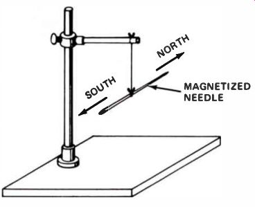
Figure 10. If a magnetized needle is suspended at its balance point,
the needle will line up in a north and south direction because it lines
up with the earth's magnetic field.
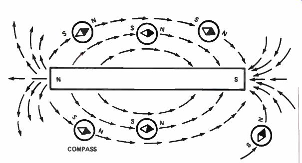
Figure 11. A small compass can be used to trace magnetic lines of force
near a permanent magnet.
Notice the similarity between the attraction and repulsion of magnetic poles, and the attraction and repulsion of electric charges. You al ready know that like charges repel, and unlike charges attract. In magnets, like poles repel, and unlike poles attract. This is a fundamental law of magnetism that you should remember.
Magnetic Lines of Force. There are lines of force surrounding a magnet. You can trace the lines of force around a magnet by using a small compass, as shown in Fig.11. When you move the compass near the north pole of the magnet, the south pole of the compass is attracted to it. The compass needle lines up with the magnetic lines of force. As you move the compass, as shown in Fig.11, you can trace out the lines of force.
You can also see the lines of force around a magnet by placing a thin sheet of cardboard over the magnet, then sprinkling iron filings evenly over the cardboard. Tap the cardboard gently and the iron filings will arrange themselves in a definite pattern, as shown in Fig.12(A). As you see, the filings are lined up with the lines of force.
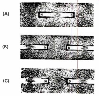
Figure 12. If iron filings are placed on a sheet of cardboard over permanent
magnets, they will trace out lines of force.
By bringing the north pole of two magnets together and performing the experiment again, you can see the repulsion between the two poles, as Fig.12(B) shows. Figure 12(C) shows the pat tern set up by the attraction between the north pole of one magnet and the south pole of another.
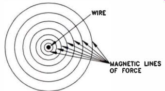
Figure 13. Cross-section of a wire. When electrons flow through a wire,
magnetic lines of force surround it.
The lines of force associated with a magnet are call: Similar lines of force surround electrically charged objects. They are called electric lines of force.
Electromagnets
Electric current flowing in a wire generates a magnetic field in the space around the wire. The production of this type of magnetic field is commonly known as "electromagnetism." The number of lines of force is greater close to the wire, and decreases with distance, as shown in Fig.13.
The relatively weak magnetic field around a single conductor can be made much stronger by winding the wire in the form of a coil, as shown in Fig.14. In a coil, the circular magnetic rings pass through the center of the coil in the same direction and reinforce each other, as shown.
This type of magnet is an electromagnet. The magnetic effect exists only as long as the current is flowing through the wire.
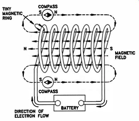
Figure 14. The more turns of a wire in a coil, the stronger the magnetic
field becomes when electrons flow through the coil.
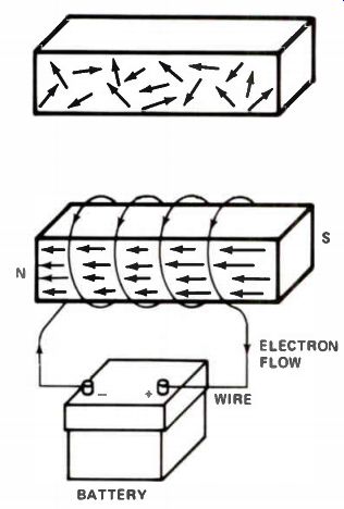
Figure 15. (A) In an unmagnetized bar of iron, the tiny magnets in the
iron do not line up. (B) If the iron bar is magnetized, they will line
up.
The electromagnet shown in Fig.14 can be made much stronger by inserting an iron bar, or a bar of some magnetic material, inside the coil.
The bar is called a core. The actual increase in the strength of the magnet will depend upon the type of core material used.
The magnetic core is composed of tiny particles, each one a small magnet with a north and south pole. Under normal conditions, these particles are randomly arranged, as shown in Fig.15(A). In the magnetic field inside the current carrying coil, the core particles arrange in a single orientation, as shown in Fig.15(B). The entire bar becomes a single strong magnet.
When the circuit opens and current flow stops, the magnetic field collapses. Most of the particles return to a random state, although some residual magnetism remains.
Induced Currents. We have seen that current flowing through a coil produces an electromagnet. Is the opposite true? If a magnet is placed inside a coil, will a current flow? A flashlight bulb connected to a coil wound on a hollow form is shown in Fig.16. When the magnet is moved rapidly from outside the coil to inside the center of the coil, the bulb will light while the magnet is moving. When the magnet stops inside the coil, the light goes out. The bulb lights again when the magnet is moved quickly out of the coil. If the magnet is moved rapidly back and forth in the coil, the bulb will light and remain lit as long as the magnet is in motion.
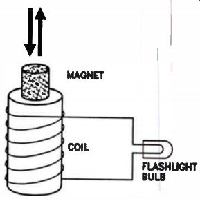
Figure 16. An illustration of how magnetic lines of force induce a voltage.
What is happening? Well, the magnetic lines of force that surround the magnet move through the turns of the wire coil. The magnetic lines of force are said to "cut" the turns of the coil as the magnet moves. This action generates, or "induces," a small voltage in each turn of the coil.
This effect continues for as long as the number of magnetic lines of force cutting the coil is changing. The voltages induced in each turn of wire add together. The total induced voltage produces a current flow through the coil and through the bulb. We call the voltage produced an induced voltage and the current an induced current, because no physical contact is made, and no chemical action takes place.
Figure 17 shows another way to induce voltage. Two coils are wound on the same form so that they are close together. One coil is labeled L1 and the other L2. Coil L1 is connected to a flashlight battery through a switch labeled SW. Coil L2 is connected to a flashlight bulb. An iron core is inserted through the form on which the coils are wound to increase the strength of the magnetic field.
Closing the switch starts current flowing in L1. The flow of current in L1 induces a voltage in L2, causing the bulb to glow briefly. The glow lasts for only an instant after the switch is closed. Opening the switch interrupts the current flow through L1. Again, the bulb glows for an instant, indicating that opening the switch also caused a voltage to be induced in L2.
The action of the two coils looks much different from the effect obtained with the moving magnet shown in Fig.16. However, the basic principle is much the same. When the switch is closed, current flows in L1, causing a magnetic field to build around it. The magnetic field builds quickly, but is not instantaneous. The expansion of the magnetic field around L1 causes magnetic lines of force to cut the turns of L2. This changing, expanding field induces a voltage in L2.
Once the field reaches its limit, the number of lines of force cutting L2 is not changing. Voltage induction then stops in L2. Opening the switch causes the field around L1 to collapse. Once again, a changing field cuts the turns of L2. As the field collapses, voltage is again induced in L2, and the lamp glows briefly.
It is important to remember that a change in a magnetic field around a coil will induce a voltage. It is a changing field that does the job; a constant field does not induce a voltage.
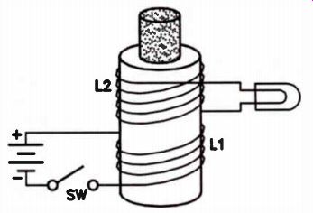
Figure 17. When the circuit to L1 is opened or closed, a voltage will
be induced in 12.
Review A magnet has a north pole and a south pole.
Invisible magnetic lines of force exist in space between the north and south poles of a magnet.
Like magnetic poles repel, and unlike magnetic poles attract.
There is a magnetic field around a current carrying wire. An electromagnet can be made by passing a current through a coil. Inserting an iron core into an electromagnet will result in a stronger magnetic field.
If the number of magnetic lines of force cutting a turn of a coil change, voltage is induced in that turn of the coil. If the magnetic lines of force cutting all the turns of a coil change, there will be a voltage induced in each turn of the coil, and these voltages will add together. If the coil is connected to a complete circuit, current will flow in the circuit.
Self-Test Questions
13 State the basic law of magnetism.
14 If a pole magnet attracts the south pole of a compass, is this a north pole or a south pole?
15 Are the magnetic lines of force around a current-carrying wire stronger close to the wire, or at a distance?
16 What effect will placing an iron core inside an electromagnet have on the strength of the magnetic field?
17 If the ends of a coil are connected to a flash light bulb and a very strong permanent magnet is placed inside the coil, will the flashlight bulb light? How long will the flash light bulb remain lit?
--------------
GENERATORS
Batteries are very useful, but their ability to supply large amounts of power is limited. Even a powerful storage battery cannot supply large amounts of current without soon being exhausted and in need of recharging. Even if storage batteries could supply the large amounts of energy consumed daily by the average large city, we would still need to have some way of recharging the battery. Thus, we would have need for a device other than a battery that is capable of supplying large amounts of electricity.
You have learned that a varying magnetic field cutting through a coil induces a voltage in the coil. If the magnetic field is made to vary constantly, a continuing voltage is induced. The induced voltage can supply current to an external circuit. This is the basic principle of an electric power generator.
Before studying generators, let's learn the differences between direct current and alternating current.
Direct and Alternating Current
Current supplied by a battery always flows from the negative terminal through the external circuit, and back to the positive terminal. The current always flows in one direction. We call it direct current, or DC current. The voltage sup plied by a battery, or any other voltage source that causes a direct current to flow, is referred to as a de voltage. One terminal on a battery is always the negative terminal and the other terminal is always the positive terminal.
A DC generator is a device that generates direct current. In other words, the current coming from a DC generator always flows in the same direction. This means that the generator terminals always have the same polarity. One terminal is the negative terminal, and the other terminal is the positive terminal. The polarity of a given terminal, negative or positive, does not change.
Devices connected to the generator make up the load. The load could be a light bulb, a motor, or a combination of light bulbs and a motor. The DC generator and the load connected to it are called the DC circuit. In a DC circuit where the generator voltage is constant and the resistance of the load is constant, the current flowing in the circuit is constant.
Alternating current, or AC current, is different from direct current. It does not have a constant value or a constant polarity. It changes continuously, according to its characteristic rate (frequency) and voltage potential (amplitude). Alternating current begins with a zero voltage and polarity. It first flows in one direction, building up to a maximum value, then returns to zero.
It then reverses direction and polarity, builds up to a maximum value in the opposite direction, and returns again to zero. This complete process is called a cycle.
While there are many devices that operate only on direct current, alternating current has many useful applications. Indeed, our modern industries depend upon large amounts of alternating current being readily available.
Let's proceed and learn more about alternating current and AC voltage, and how a simple generator operates.
A Simple Generator
A simple generator of electric current and voltage can be built as shown in Fig.18. This is intended only as an example, and consists of a single turn of wire placed between the poles of a magnet. As the coil rotates, it cuts the magnetic lines of force between the north and south poles of the magnet. This induces a voltage in the coil.
The amount of voltage produced depends upon the number of magnetic lines cut by the coil as it rotates, which in turn depends upon the strength of the magnetic field and the speed at which the coil is rotated.
What is the nature of the voltage produced by this generator? When the coil is in the position shown in Fig.19(A), it is moving mostly in a direction parallel to the lines of force between the magnetic poles. Therefore, it is not cutting through any lines of force, but only moving parallel to them. Remember, to induce a voltage, the turns of the coil must cut through magnetic lines of force. In Fig.19(A) the coil is not cutting lines of force, so no voltage is induced.
As the coil rotates towards the position shown in Fig.19(B), it begins moving at an angle to the lines of force, and cuts through an increasing number as it moves. Thus, a proportional amount of voltage is induced in the coil. As movement continues toward the position shown in Fig.19(C), more voltage is induced as the coil moves at a sharper angle to the lines of force.
Finally, when it reaches the position shown in Fig.19(D), it is moving directly perpendicular to the lines of force, cutting through them at a maximum rate. The voltage induced is at its highest value as the coil moves through the perpendicular point. Continuing to turn, the coil moves through the positions shown in Figures 19(E) and 19(F). It cuts fewer and fewer lines of force until it reaches the position shown in Fig.19(G). Here, the coil is once again moving parallel to the lines of force, so no voltage is being induced.
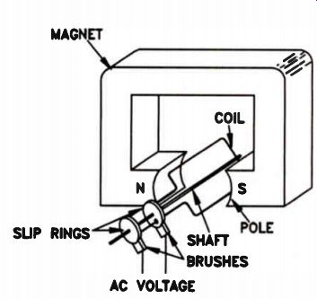
Figure 18. A simple AC generator.
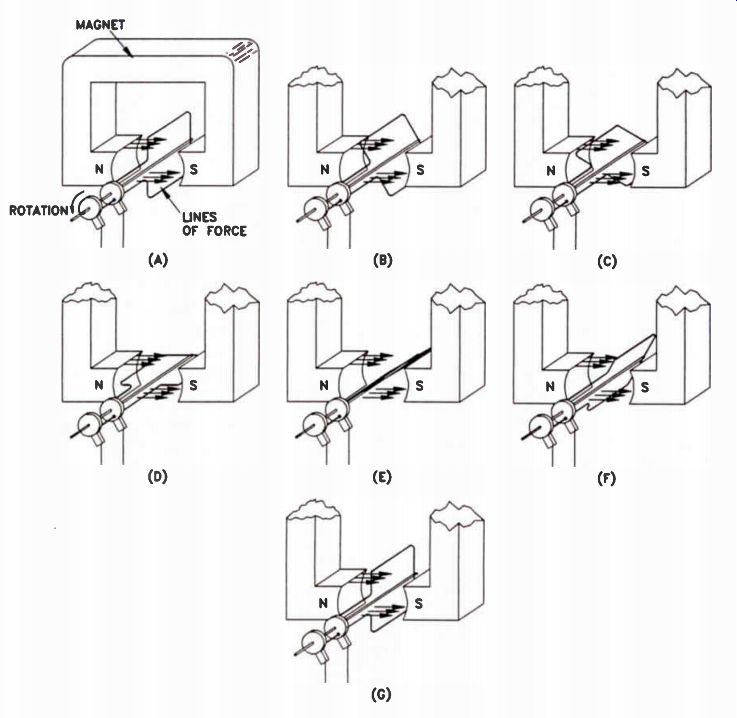
Figure 19. In this illustration, the coil is rotating counterclockwise.
The voltage produced by this generator depends upon the movement of the
coil in relation to the magnetic lines of force.
How Voltages Are Pictured
When we discussed series-connected batteries, we said that one terminal of the two batteries could be considered zero, and the voltage at the other terminals marked in reference to this terminal. You can do the same thing with a generator. You can use one lead as the ground or common lead and measure the voltage at the other lead as either positive or negative with respect to the common lead.
If we assume that one lead is a common or ground lead (or has zero voltage), we can represent the voltage at the other lead as a line on a graph. In Fig.20, the horizontal line across the center of the graph is the zero voltage line; it represents the voltage at the ground, or common lead. Each horizontal step above the zero line represents a positive voltage. Lines below the center zero line represent negative voltages. The vertical lines each represent one position of the coil from Fig.19.
To have the convenience of round figures, let's assume the coil generates 100 V at the instant it is in the position shown in Fig.19(D). If the voltage is +100 V with respect to the common terminal, we would place a mark (X) on the graph at the point where the +100 V line crosses the vertical line running through D, as shown in Fig.20(A). Similarly, the voltages induced at the other points would be marked on the graph. This would look like Fig.20(B). We then draw a smooth curve joining all these points, as shown in Fig.20(C). This curve represents the voltage produced by the generator through one-half turn.
As the coil rotates through the remaining half turn, the voltage polarity reverses. It will be negative with respect to the ground terminal because the coil cuts through the magnetic lines of force from the opposite direction. This produces a curve on the graph like Fig.21(A). Removing the horizontal and vertical reference lines, we can get a better look at the shape of the output voltage, as in Fig.21(B). This is called a waveform.
This waveform is how AC voltage supplied by the power company is commonly represented. It is called a sine (pronounced sign) wave. The voltage represented by one complete turn of the coil in the magnetic field is a cycle. The power supplied by most power companies in this country is 60-cycle power.
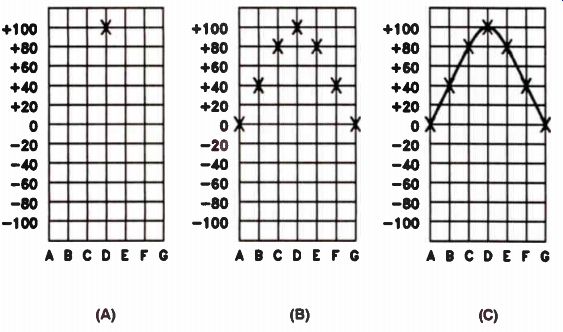
Figure 20. Construction of a graph of the voltage produced by the generator
in Figure 11.
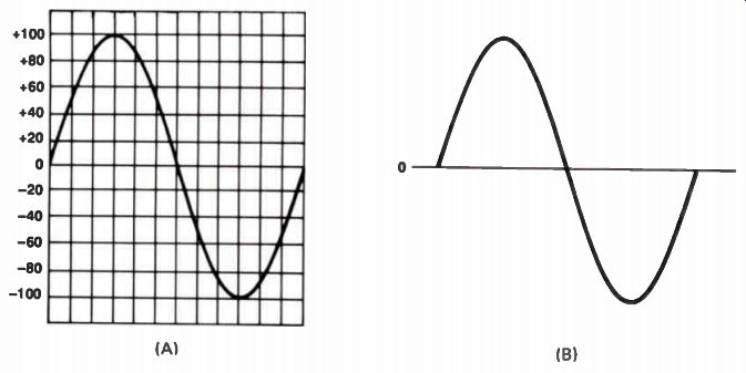
Figure 21. The appearance of the output voltage produced by the generator
as it travels through one complete turn.
When we say 60 cycle, we mean 60 cycles per second. That is, the voltage goes through 60 cycles, like the one shown in Fig.14, each second.
This is called the frequency of the AC voltage. To make the two-pole generator like the one in Fig.18 produce this type of voltage, it must turn at a speed of 60 revolutions per second, which is 3600 revolutions per minute (rpm). The part of the cycle above the line is called a positive half cycle. The half-cycle below the line is the negative half-cycle. The highest voltage reached du' the cycle, 100 V in this case, is called the peak voltage. There exe- two peaks: a positive and a negative peak. Each peak is 100 volts. The peak-to-peak voltage, which is the total voltage between the positive peak and the negative peak, is 200 volts. Remember these terms; they will be used frequently in this course.
Another term for frequency of AC voltage is hertz, abbreviated Hz. Hertz and cycles-per second mean exactly the same thing. These expressions are interchangeable, though hertz is the preferred term. When you see the expression 60 Hz, it refers to an alternating voltage, or current, that completes 60 cycles per second.
The voltage generated by this one-turn primitive generator would be extremely low, even with a very strong magnetic field. But higher voltages can be obtained by putting more turns of wire on the coil. In fact, 10 times as much voltage is induced in a 10-turn coil as in a single-turn coil.
If one-tenth of a volt is induced in a 1-turn coil, one-tenth of a volt is induced in each turn of a 10-turn coil. These voltages add together to make a total of 1V available at the output terminals. With 100 turns of wire, we can get 10 V; 1000 turns on the coil would produce 100 volts.
Thus, by putting the required number of turns on the coil of a generator, we can generate any desired voltage.
DC Generators
A practical generator does not use a permanent magnet. Instead, an electromagnet supplies the magnetic field. Operating current for the electromagnet can be obtained from the generator itself, from another generator, or even from a battery However, de current is required to make an electromagnet. The voltage produced by the generator we discussed is ac. How can we get DC current from an AC generator? A practical AC generator does not use direct physical connections to the wire winding of the coil. The coil rotates at a high speed, which would quickly twist and break off solid connections. So, the ends of the coils connect to slip-rings. Brush contacts ride on the slip-rings, allowing AC voltage to be tapped from a generator. The slip-ring and brush surfaces are precisely-machined parts; the brushes glide over the surface of the slip-rings as the coil rotates, keeping excellent electrical contact with minimum abrasion.
However, we can get DC output if we use two slip-rings and a commutator, as shown in Fig. 22.
A commutator resembles a slip-ring, but it is split in half and the two halves are insulated from each other. The brushes are placed so that each brush contacts one section of the commutator as the coil makes the first half-revolution, and the other section of commutator as the coil makes the second half-revolution. The result is that current in the external circuit always flows in the same direction, as shown in Fig.23. As a result, at the output we have a voltage like that shown in Fig.24.
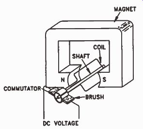
Figure 22. A simple DC generator.
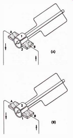
Figure 23. (A) Section 1 of the commutator is negative, and section
2 is positive. (B) Section 1 is positive, and section 2 is negative.
Brush A is always connected to the negative section of the commutator,
and brush B to the positive section. Current flows in only one direction.
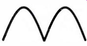
Figure 24. Output of a simple DC generator.
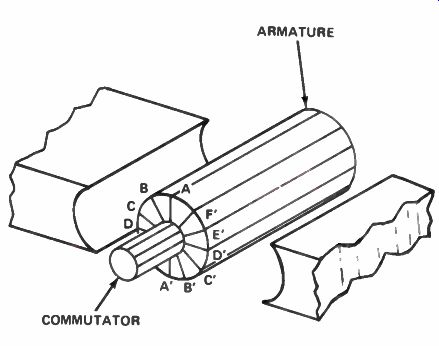
Figure 25. The armature of a DC generator with six series-connected
coils.
This is essentially the same wave shape as in Fig. 21. The difference is that the negative half cycle below the line is made positive by the automatic reversing of the connections to the coil achieved by the commutator and brushes.
Voltage like that shown in Fig.24 is called pulsating dc. It is defined as a de voltage because the current flows in one direction. However, since the voltage varies, the amount of current also varies. The current flows in pulses and actually drops to zero twice during each turn of the coil. Pulsating current can be used in some applications, but it is troublesome because it is not pure dc, like the DC supplied by a battery.
A more efficient generator design is shown in Fig.25. Here there are a number of coils wound on an iron form called an armature. The coils are in different positions around the armature. In the position shown, coil A-A' does not cut any lines of force and has no voltage induced in it.
Coil B-B' is in a position to cut a few lines of force, and has some voltage induced in it. Coil C-C' is further into the magnetic field, cutting still more lines of force and generating a proportional amount of voltage. Coil D-D' is cutting directly across the lines of force and the maximum voltage will be induced in it. These coils are connected in series and brought out to the connections on the commutator. Two brushes are used on the commutator. The output voltage from this type of machine will be nearly constant because there will always be one coil in or near each position shown in Fig. 25. The voltage produced by the generator will be the voltage of all the coils in series.
While some of the coils are producing very little voltage, the coils near the position D-D' will produce considerable voltage. The commutator used with this type of generator has 12 sections instead of two. There will be some fluctuation in the output voltage, but not nearly as much as in a generator with a single coil.
If we designed the 6-coil generator shown in Fig.25 so that its maximum output voltage was 100 V, during the first half-revolution the voltage would rise from 95 V to 100 V, then fall back to 95 V six times. The same thing would happen during the next half-cycle. The advantage is that we can reduce the voltage variation with a 6-coil machine. The single-coil machine, on the other hand, would vary between 0 and 100 V every half-turn. Compare the output from a 100 V single-coil de generator to the output from a 100 V 6-coil DC generator shown in Fig.26.
AC Values
Look back at the 1-cycle AC waveform shown in Fig.21. At the start of the cycle, the voltage is zero. After the coil rotates one-quarter of a turn, the voltage reaches its maximum value. At the halfway point, its back to zero again. At three quarters of a turn, the voltage is at its maximum negative value, and at the end of the cycle the voltage is back to zero. The voltage reaches a maximum value twice in each cycle.
Since AC voltage fluctuates constantly, how do we measure its applied value? When we talk about a de current, we might say that the current flowing in the circuit is 1 ampere. This means that a certain number of electrons flow past a given point in the circuit in a period of one second. This same number of electrons continues to flow as long as the current is 1 ampere.
What happens with AC current? With the voltage rising and falling twice each cycle, the current flow has two maximum and two minimum points in each cycle. Therefore, the number of electrons flowing in the circuit is not constant.
In fact, it changes continuously as the AC voltage goes through its cycle.
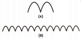
Figure 26. (A) Voltage from a single-turn generator. (B) Voltage from a
generator with coils like in Figure 25.
To get around the difficulty caused by its constant variation, we measure AC in terms of equivalent dc. When we say that the AC current flowing in the circuit is 1A, we mean that the current is the equivalent of 1A of dc. This equivalence is established on a basis of com parable heat produced. For instance, a de current of 1A flowing through a heating element generates a certain measurable amount of heat.
When AC current flowing through the same heating element produces the same amount of heat, we define that AC current as 1 ampere.
Basically, the same system is used to measure AC voltage. If a de voltage of 100 V forces a current of 1 A through a standard resistance, the AC voltage that forces an AC current of 1A through the same resistance is said to be 100 volts. This is called the effective, or rms voltage.
An AC current that flows as a result of this voltage produces the same heating effect as the equivalent amount of de current.
From looking at an AC voltage waveform, you can see that the actual voltage is greater than the effective value during part of the cycle, and less than the effective value during the rest. The maximum voltage that the AC reaches during a half-cycle is called the peak voltage, as we mentioned before. The peak voltage is approximately 1.4 times the effective voltage. Since each peak is 1.4 times the effective voltage, the peak-to-peak voltage is twice that, or 2.8 times the effective voltage. Figure 27 shows an effective AC voltage of 100 volts. The peak value is 140 V, and the peak-to-peak value 280 volts. Study this figure carefully to be sure that you understand it.
It is important to remember that when we are talking about AC voltages, unless we specifically refer to the peak or peak-to-peak voltages, we are talking about effective voltages. Also remember that the peak voltage is 1.4 times - the peak-to-peak voltage is 2.8 times--the effective voltage. Peak voltage, peak-to-peak voltage, and rms voltage are terms you will see many times during your career in electronics. Remember that rms voltage is the same as the effective voltage.
A good example for comparison of voltage measurements is the voltage supplied to most homes in this country The average power company supplies a voltage of somewhere between 115 and 120 volts, 60 Hz ac, for lighting and general domestic use. This is the effective value of the voltage. Let us assume that the voltage supplied to your home is exactly 120 volts. What is the peak voltage reached during each half cycle? It will be 1.4 x 120, which is 168 volts. The peak-to-peak voltage supplied to your home will be 336 V (or 2.8 x 120). The net effect of this AC voltage is the same as supplying a DC voltage of 120 V to the electric light.
The Importance of AC. You may wonder why we have gone into so much detail in describing alternating current. Alternating current is important not only because it is the type of power supplied by the power companies, but also Because AC signals are used throughout the entire electronics industry The sound that comes from the loudspeaker in a radio or telephone receiver, or the sound from your telephone, is produced by AC signals having a frequency not too much higher than the power-line frequency. The radio waves that travel through space to bring you radio and TV programs are actually AC signals of a much higher frequency. AC signals are used in every branch of electronics. In later lessons you will learn how these signals are produced and how they are used. You will also learn that many circuits and components have different behaviors when an AC voltage is applied, as com pared to when a de voltage is applied. You will learn how we take advantage of these differences.
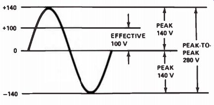
Figure 27. AC waveform showing effective (rms), peak, and peak-to-peak
voltages.
Review
We have covered a great deal of material in the preceding sections. There are several important things that you should remember, including what an AC cycle looks like, and that this AC voltage is called a sine wave.
Remember that when we speak of AC voltage and current, we are speaking of the voltage and current that will produce the same effect as the equivalent values of dc. Remember that the peak value of the AC cycle is 1.4 times the effective value, and the peak-to-peak value is 2.8 times the effective value.
Self-Test Questions
18. What are the two kinds of electrical current produced by power sources?
19. What kind of voltage produces a current that flows in only one direction?
20. What do we call voltage that causes current to flow first in one direction, then in the other direction, many times in a second?
21. What is the name given to the AC voltage waveform supplied by the power company?
22. What is a cycle?
23. What do we mean by 60 Hz?
24. What device on a de generator reverses the ' connections of the coil to produce direct current instead of alternating current?
25. What type of current is produced by a, simple DC generator?
26. What is the difference between 1 A of de r current, and 1 A of AC current?
27. If we say the AC voltage is, 100 V, are we referring to the , effective dr the peak value of the AC voltage?
28. If the rms voltage is 200 V, what is the peak value of the voltage?
ANSWERS TO SELF-TEST QUESTIONS
1. Primary and secondary are the two basic types of batteries.
2. Secondary batteries are rechargeable.
3. Electrical power in a battery is the result of chemical reaction.
4. Primary batteries have the advantage of a longer shelf life (storage period) without severe loss of charge.
5. The chemical reaction in a dry cell is caused by metals such as zinc or lead, and their oxides.
6. A fresh carbon-zinc battery has a 1.5 V un loaded output voltage. The typical no-load voltage of a dry cell, or zinc-manganese (carbon zinc) battery, is 1.5 volts.
7. Alkaline batteries get their name from their caustic alkaline base of potassium hydroxide, which is used as part of the electrolyte.
8. In conditions of low current drain at a constant warm temperature, carbon-zinc batteries may be more economical than alkaline batteries.
9. The no-load voltage of a lead-acid cell is 2 V, plus or minus 10%, depending on conditions.
10. The normal recharge rate for a nickel cadmium cell is approximately 10% of the rated current output.
11. A fully-charged nickel-cadmium battery starts at about 1.4 V and quickly drops to a constant 1.25 volts.
12. The lithium battery has the longest shelf life.
13. The basic law of magnetism states: Like poles repel, and unlike poles attract.
14. The basic law of magnetism addresses this statement: If one pole of the magnet attracts the south pole of the compass, the pole must be an unlike pole, and therefore must be a north pole.
15. The magnetic lines of force around a current carrying wire are stronger close to the wire.
16. Placing an iron core inside an electromagnet will increase the strength of the field.
17. The flashlight bulb will light while the mag net is being placed inside the coil. Once the magnet is inside the coil and no longer moving, the flashlight bulb will no longer light.
18. Electrical current power sources produce both direct current and alternating current.
19. DC voltage flows in only one direction.
20 AC voltage causes current to flow first in one direction, then in the other direction, many times a second.
21. The waveform supplied by the power company is called a sine wave.
22. The waveform shown in Fig.21(B) represents one cycle. In a cycle of an alternating current, the voltage between the two terminals of the generator starts at zero, then builds up to a maximum value with one polarity, then drops back to zero; it then builds up to a maximum value with the other polarity, and then drops back to zero. During the next cycle it will simply repeat the first cycle.
23. The measurement of 60 Hz means 60 cycles per second, which means that there are 60 complete cycles in a second. This means that the voltage starts at zero, builds up to a maximum with one polarity, drops back to zero, builds up to a maximum value at the opposite polarity, and drops back to zero a total of 60 times in a second.
24. A commutator reverses the connections of 27 the coil to produce de voltage.
25. A simple de generator, like the one shown in Fig.22, would produce a pulsating de (shown in the waveform in Fig.24). A pulsating de of this type is normally not desirable, and the 28 excessive pulsating can be eliminated by means of an armature, such as that shown in Fig.25. The armature holds several coils connected in series to produce a smoother DC output.
26. Actually, 1A of DC current and 1 A of AC current flowing through a heater produces the same amount of heat as a de current of 1 A flowing through the same heater.
An AC voltage that is not specified as a peak value is assumed to be the effective or rms value. If we want to provide the peak value, we should specifically state that it is the peak value, or assume the effective (rms) value.
With a rms voltage of 200 V, the peak value of the voltage is 280 volts. The peak value of an AC voltage is 1.4 times the rms value. Thus, if the rms value is 200 V, the peak value is 280 V (or 200 x 1.4).
--------------------
Lesson Summary
Some of the important facts you should remember about this lesson are:
• Primary storage batteries are not rechargeable; secondary batteries are.
• The movement of a conductor within a magnetic field generates current and voltage in the conductor.
• The voltage that is produced in a conductor coil, by movement in a magnetic field, is proportional to the strength of the magnetic field and the number of turns in the coil.
• Both AC and DC generators are constructed from multiple sets of magnets and multiple windings of wire.
• AC current is in the form of a sine wave with peak, effective, and peak-to-peak voltage and current characteristics.
LESSON QUESTIONS
This is Lesson Number 2220. Make sure you print your name, student number, and lesson number in the space provided on the Lesson Answer Form. Be sure to fill in the circles beneath your student number and lesson number.
Reminder: A properly completed Lesson Answer Form allows us to evaluate your answers and speed the results and additional study material to you as soon as possible.
Do not hold your Lesson Answer Forms to send several at one time. You may run out of study material if you do not send your answers for evaluation promptly.
1. The basic difference between a primary cell and a secondary cell is:
a. A secondary cell can be recharged.
b. A primary cell can be recharged.
c. A secondary cell has a higher voltage.
d. A primary cell has a higher voltage.
2. Notice how the cells are connected in the diagram. If each cell has a voltage of 2 V, the voltage applied to the bulb is:
a. 2 volts.
b. 4 volts.
c. 6 volts.
d. 8 volts.
3. If two 9 V batteries are connected in series as shown, what is the polarity and voltage of terminal B with respect to terminal C?
a. +9 volts.
b. -9 volts.
c. +18 volts.
d. -18 volts.
4. If a permanent magnet is held motionless in side a coil, will a voltage be induced in the coil?
a. Yes.
b. No.
c. Only if there is a complete circuit.
d. Only if there is an iron core.
5. When we say that the effective AC current is 1A, we mean:
a. A constant current of 1 A flows.
b. The peak current is 1 ampere.
c. The current flowing has the effect of 1A dc.
d. The average current is 1 ampere.
6. If the effective AC voltage produced by a generator is 10 V, the peak voltage is:
a. 10 volts.
b. 0 volts.
c. 28 volts.
d. 14 volts.
7. If a two-pole, single-turn AC generator is turning at 1800 rpm, what is the frequency e AC produced?
a. 30 Hz.
b. 60 Hz.
c. 15 Hz.
d. 75 Hz.
8. If you find that when you bring two magnetic poles together they attract each other:
a. The two poles must be north poles.
b. The two poles must be south poles.
c. One pole must be a north pole and the other a south pole.
d. Both answers a and b may be correct.
9. The chief advantage of the dry cell over the lead-acid cell is:
a. It supplies a higher voltage.
b. It can supply a given current longer.
c. It has a longer shelf life.
d. It is cheaper to manufacture.
10. To induce a voltage in a conductor, what two things are needed?
a. Magnetic field and motion.
b. Copper and magnetism.
c. Electrolyte and reactive metal.
d. Current and resistance.
-------------------
NRI Schools
CASHING IN ON DISCONTENTMENT
Discontentment is a good thing - if it makes you want to do some thing worthwhile. If you had not been discontented with your current situation, you never would have enrolled in your NRI course.
Practically everyone is discontented from time to time. If we allow ourselves to be floored by discontentment, we can easily become complainers who find fault with anything and everything and end up bitter and resentful failures.
If we're smart, we learn to use our discontentment to motivate us.
We use it to keep us focused on the goals we have set for ourselves.
We know that we are creating a better life for ourselves, so sacrifices are worth making. We are happy in our work. We face defeat squarely and come out winners.
At this moment, you may be discontented with many things - your progress in this course, your current earning ability, or your life in general.
Make that discontentment work for you. Don't let it get you down.
If you do, you may not be able to pick yourself back up again. Keep striving to beat the causes of your discontentment. Remember that it's always darkest before the dawn. And remember, the people who are real successes in life work their hardest when they are face to face with the greatest discouragements and disappointments.
The McGraw-Hill Companies
---------------------------