AMAZON multi-meters discounts AMAZON oscilloscope discounts
Table of Contents:
- How Resistors Are Used
- Physical Characteristics of Resistors
- Resistor Types
- Resistor Values Tolerances EIA Values
- Color Code
- Precision Resistors
- Thermistors
- Varistors
- High-Voltage Resistors
- Resistor Wattage Ratings
- Review
- Self-Test Questions
- Using Resistors to Set Circuit Voltages
- Voltage Division
- Series-Dropping Resistors
- Bleeder Resistors
- Review
- Self-Test Questions
- Answers to Self-Test Questions
- Lesson Questions
----------
Lesson Objectives
In this lesson, you will ...
• Review resistor types, constructions, and tolerances.
• Learn the resistor color code for identifying resistors.
• Examine how resistors are used to establish circuit voltages.
• Study how resistors can stabilize voltage sources.
This lesson is devoted almost entirely to resistors and their uses. It is important that you learn how they are used so that you can determine if a circuit is working properly. You also need to be able to select a suitable replacement for a resistor when one is needed.
There are many uses for resistors. Different circuits require different operating voltages but, for economy, the required operating voltages must all be obtained from a single power source.
Resistors are used to drop the voltage to the correct value. Resistors are also used to isolate parts from each other so that one will not interfere with the operation or action of another.
PHYSICAL CHARACTERISTICS OF RESISTORS
Resistors come in many shapes and sizes, and with several different design parameters. The design of a resistor depends mostly upon the application for which it is intended. Special variable resistors, called potentiometers, are widely used in electronic equipment to control the volume and tone in radio and TV receivers, and to control picture brightness and contrast in TV receivers and video displays. They also control the level of the sound signal in radio transmitters, and the level of both sound and picture signals in TV transmitters. There is no end to the uses of resistors in electronic equipment, so it is important that you understand how they work and are used.
Resistor Types
We have already introduced several types of resistors used in electronic equipment, of which the most frequently used is the carbon resistor.
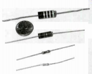
Figure 1. Relative physical size of the four different watt age carbon
resistors compared to a penny.
There are two types of carbon resistors; one is made of a carbon compound held together by a cement-type binder, and the other is made by depositing a film of carbon on a thin ceramic rod.
Carbon resistors are manufactured in 1/4 W, 1 W. and 2 W. Devices such as video cassette recorders and microcomputers contain hundreds of carbon resistors. Most of the carbon resistors in these devices are 1/4 W or 1/2 W resistors.
There are also wire-wound resistors. A wire wound resistor made by winding a resistance wire on a form. Resistance wire is a special type of wire that has a relatively high resistance.
Figure 1 is a photograph showing the relative physical size of the four different watt age carbon resistors as compared to a penny.
Wire-wound resistors have wattage ratings that start at 3 or 4-W, and range upward to very high wattage ratings. Very high wattage rating resistors are large and heavy and are often suspended on mounting brackets, bolted, or riveted to the chassis. Wire-wound resistors cannot be made conveniently in high resistance values. Since they are made by winding wire in a coil on an insulated support, they often take on some of the characteristics of a coil, which may not be desirable.
Metal-oxide resistors are another type. These resistors can be made in higher wattage ratings than carbon resistors, yet still have many of the advantages of carbon resistors. Where larger values of resistance are necessary, metal-oxide resistors must be used instead of wire-wound resistors. The metal-oxide resistor is made by depositing a metal-oxide film on a ceramic or glass tube or rod. The oxide film is in a linear path rather than a winding path, so it does not act like a coil.
The rheostat is one kind of variable resistor.
Rheostats may be wire-wound devices, or may be made from a carbon element. A rheostat has a sliding contact which rotates to allow selection of the desired resistance. The resistance is deter mined by the position of the sliding contact with respect to the total resistance available.
The variable resistor shown in Fig. 2 is a potentiometer. A potentiometer has three terminals. The resistance between the two outside terminals is constant - equal to the entire resistance of the carbon or wire-wound element inside the control. The center terminal connects to a sliding contact and is adjustable across the resistance element. Like the rheostat, the resistance between the sliding contact and either end of the total resistance is selected by turning the control. Since the total resistance is constant, when the resistance between the slider and one end of the resistance element decreases, the resistance between the slider and the other end increases.
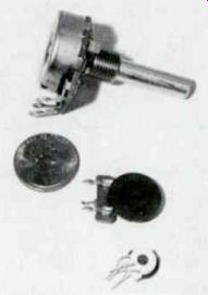
Figure 2. A potentiometer.
Potentiometers with high resistances are usually carbon control. Low-resistance potentiometers may either be carbon or wire-wound controls; most, however, are carbon controls.
Carbon controls are preferred over wire-wound controls because they are less likely to develop dirty or burned spots on the resistance element.
These spots produce noise as the control is rotated.
Resistor Values
You should know from your previous lessons that a wide range of resistor values are used in electronic equipment. You should also remember that in abbreviating resistor values the letter k represents a thousand and the letter M represents a million. Thus, a resistor marked 2.2k has a value of 2200 ohms. A resistor marked 2.2 M has a resistance of 2,200,000 ohms. To convert from kilohms to ohms, move the decimal point three places to the right. To convert from ohms to kilohms, move the decimal point three places to the left. To convert from megohms to ohms, move the decimal point six places to the right, and to convert from ohms to megohms, move the decimal point six places to the left.
Sometimes you must convert from megohms to kilohms. For example, a resistor might be marked 0.1 M. To convert this to ohms, move the decimal point six places to the right. Thus, 0.1 M becomes 100,000 ohms. To convert from megohms to kilohms, move the decimal point three places to the right. Therefore, a 0.1 M resistor is the same as a 100k resistor. You will find resistors marked 470k on some diagrams, and 0.47 M on others.
Remember that both mean the same thing: the resistance of the resistor is 470,000 ohms.
Tolerances
The carbon resistor is the most widely used resistor in electronic equipment. These resistors are manufactured with a tolerance of either 5 or 10%. Occasionally, you will come across a carbon resistor with a tolerance of 20%, but these resistors are infrequently used.
The tolerance of a resistor indicates how close its actual resistance is to its rated resistance.
Consider a 100-ohm resistor with a 5% tolerance.
You will find that 5% of 100 is 5 ohms. If the resistor has a 5% tolerance, its actual resistance is within 5 ohms of 100 ohms. That is, the resistor may have a value anywhere between 95 and 105 ohms. A 10% tolerance in a 100-ohm resistor is 10 ohms. A 10% resistor may have a value anywhere within 10 ohms of 100 ohms, a value between 90 and 110 ohms.
Resistor tolerance is indicated on the body of the resistors with a silver band. A silver band indicates a tolerance of 10% and a gold band a tolerance of 5 percent. A carbon resistor without silver or gold tolerance band is a 20% resistor.
EIA Values
The EIA (Electronics Industries Association) has set up standard values for carbon resistors.
In designing electronic equipment, you will rarely need a resistor of an exact value. Although, for example, an engineer might calculate that a particular circuit requires a 3721-ohm resistor, that is a nonstandard value. However, 3600 is a standard value, and so is 3900 ohms. Minor changes in the circuit would easily allow one of the standard values to be used.
Standard EIA carbon resistor values are shown in Fig.3. All these values are available in resistors having a 5% tolerance. You can get a carbon resistor having a resistance as low as 0.24 ohm, and as high as 22 megohms. However, 10% resistors are available only in the values that are shaded.
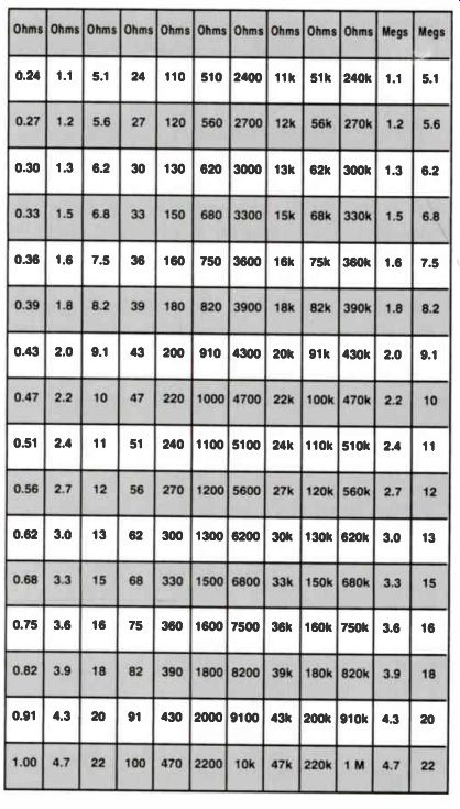
Figure 3. Standard EIA resistor values.
Older equipment usually has higher percent ages of 10% tolerance resistors. These resistors were less expensive to manufacture, and a 5% resistor was seldom needed. However, new and improved resistor-manufacturing hardware can produce, measure, and sort resistors to the nearest 5% value. Today most resistors are 5%, because they are priced comparably to 10% resistors.
When replacing a 10% resistor you can always substitute a 5% unit. However, this allowance is one way; you cannot replace a 5% tolerance resistor with a 10% part. It is possible that substituting a 10% resistor for a 5% resistor will alter the performance of the circuit. However, if the industry trend toward 5% tolerance continues, it may soon be impossible to buy a 10% resistor at all.
Color Code
The resistance value of a carbon resistor is specified by three color bands around the body.
To determine the value of a resistor, first find the tolerance band; it will either be silver or gold.
Hold the resistor so that the tolerance band is on the right, as shown in Fig.4. The three color bands are to the left of the tolerance band. From left to right, the color of the first band represents the first digit of the resistance value, the second band color indicates the second digit, and the color of the third band (sometimes called the multitier) indicates the number of zeros to add to the two-digit number formed by the first and second bands.
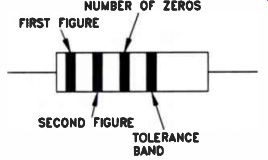
Figure 4. Resistor values and tolerance are identified by color bands
as shown.

Figure 5. Standard resistor color codes.
The standard resistor color codes are shown in the chart in Fig.5. Referring to this chart, sup pose the first band is yellow, the second band is purple, and the third band is orange. The yellow band stands for the first digit in the resistance, or 4. The purple band means the second digit is 7, and the orange band adds three Os after the 7.
Therefore, the resistance value is 47,000 ohms, or 47 kilohms.
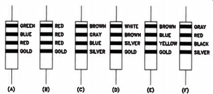
Figure 6. (A) 5600 ohms, 5.6k, 5%; (B) 2200 ohms, 2.2k, 5%; (C) 18,000,000
ohms, 18M, 10%; (D) 0.91 ohms, 5%; (E) 160,000 ohms, 160k, 5%; (F) 82
ohms, 10%.
A resistor coded red, red, brown has a resistance of 220 ohms. A black band in the third position means no Os are added, so a resistor coded red, red, black has a resistance of 22 ohms.
A gold band represents a 0.1 multiplier; there fore, a resistor coded red, red, gold has a resistance of 2.2 ohms, because you move the decimal point one place to the left to indicate multiplication by 0.1. If, in addition to the third gold band, the fourth band (or tolerance band) is gold, the resistor value is 2.2 ohms with a 5% tolerance. If the tolerance band is silver, it means that the resistor value is 2.2 ohms with a tolerance of 10%. A few resistors have a fifth color band after the tolerance band. This is a reliability indicator, and is of little concern to the electronics technician.
Resistors rarely fail unless there is a an overload failure in the circuit. When the circuit fails, the resistor may burn out regardless of its reliability.
Figure 6 shows several resistors, and the caption gives the value of each of these resistors.
Cover the caption and try writing out the resistor values. After you write out all the values, check your answers against the values given in the caption.
Precision Resistors
In some equipment, usually electronic test equipment, resistors having tolerances of 1% or 1/2% are used. These resistors are made by a different process than the carbon resistors used in most equipment, and are significantly more expensive than standard resistors.
These 1% and 1/2% resistors are called precision resistors. Their value is usually stamped on the resistor body, along with their tolerance. Although many precision resistors are available "over the counter," some special application units have to be ordered from the manufacturer or an authorized distributor.
Thermistors
A thermistor is a special type of resistor. Thermistors are made of a material that decreases in resistance as its temperature increases. We say that a thermistor has a “negative temperature coefficient." This means that as the-temperature thermistor goes up, its resistance goes down.
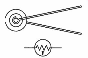
Figure 7. A typical thermistor and its schematic symbol.
A typical thermistor and its schematic symbol are shown in Fig.7. These devices are frequently used in circuits where there is likely to be a high current surge when the equipment is turned on.
When the thermistor is cold it has a high resistance, and most of the applied voltage is dropped across the thermistor. This limits the amount of current that can flow in the circuit. However, as the thermistor warms up, its resistance decreases (sometimes to a very low value) so that normal current can flow in the circuit.
Varistors
Another special type of resistor is the varistor.
This type of resistor is also called a voltage dependent resistor, which means that the resistance of the device depends upon the voltage across it. As the voltage across a varistor increases, the resistance of the varistor decreases.
A drawing of a varistor and its schematic symbol are shown in Fig.8. Varistors are used in circuits where a high voltage might appear suddenly. When this happens, the resistance of the varistor decreases rapidly, drawing off a large current from the voltage source, and preventing damage to other components. Varistors are frequently used in color TV receivers and video displays.
High-Voltage Resistors
In some applications, resistors are used across circuits where there is a very high voltage. The resistance of the resistor may be so high that the power dissipation is less than 1/2 W, but a 1/2 W carbon resistor is not suitable for high-voltage applications.
A typical high-voltage resistor is shown in Fig.9, on page 8. It is made by depositing carbon in a spiral groove cut in a ceramic-type body. The resistor is deliberately made several inches long so that there is no possibility of the high voltage arcing across it. Resistors of this type are found in TV receivers, especially color TV receivers.
Resistor Wattage Ratings
As you know, electrical power is measured in watts. In a previous lesson, you were introduced to three forms of the power equation: P = EI, P = I^2R, and P = E^2/R. In most cases, a resistor in an electrical circuit conducts some amount of current flow. For a 1/4 W resistor, the square of the current 1 2 times the value of the resistor R should not exceed 1/4 watt. For a 1/2 W resistor, I^2R must not exceed 1/2 watt. This is the case for any wattage rating, because exceeding the rating may result in the destruction of the component.
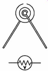
Figure 8. A typical varistor and its schematic symbol.
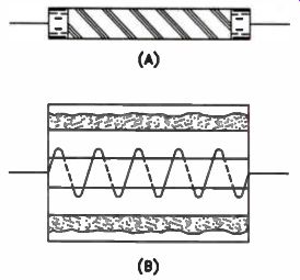
Figure 9. A high-voltage resistor.
The wattage rating of a resistor is sometimes lied its dissipation rating. A 1/2 W resistor can dissipate power. The resistor consumes electrical power by dissipating, or radiating, it as heat. In actual practice, if the power in a circuit is 1/2 W, we typically use a 1 W resistor, which has twice the dissipation capability necessary. When carbon resistors get hot, they tend to change value. Therefore, it is a good idea to use a larger resistor with a higher power dissipation tin to avoid this problem.
The deposited-film type of resistor is made in ratings of between 2 W and about 10 watts.
These resistors are larger than carbon resistors and can handle more power. Unlike carbon resistors, they do not have the tendency to change value when hot, and can be operated closer to their full wattage rating.
Wire-wound resistors can be made with extremely high wattage ratings. You will seldom find wire-wound resistors rated at higher than 10 W in a radio, TV, or microcomputer. However, in radio and TV transmitting equipment, as well as industrial equipment, some wire-wound resistors can dissipate several thousand watts or more. These high-wattage resistors are made from large-diameter resistance wire that can carry a high current. They are wound on big ceramic tubes to provide a large area to dissipate the heat produced by the current flowing through the resistance wire.
Review
You have reached the point in your course where you should be able to convert ohms to kilohms and to megohms, and then back again without any trouble. This is important because all three units are used by manufacturers on circuit diagrams.
You should memorize the resistor color-code chart. Start by writing it out several times; start with black 0, brown 1, red 2, and so on. It is not very important to remember gold and silver in the third band, because you seldom encounter small-value resistors. However, remember the meanings of the tolerance bands: gold is more valuable than silver and has a value of 5%, and silver has a value of 10 percent. The fifth band is a reliability band. Any time you have to replace a 10% resistor you can use a 5% resistor of the same value.
A thermistor is a resistor which has a resistance that decreases as the resistor warms up. A varistor is a resistor with a resistance which decreases as the voltage across it increases. A high-voltage resistor is a special resistor made several inches long so that the high voltage in the circuit will not jump across it.
Self-Test Questions
1. What is 4.7k equal to in ohms?
2. Express 0.39 M in kilohms and in ohms.
3. What is 680,000 ohms in kilohms and in megohms?
4. A 2200-ohm, 10% resistor actually has a value of 2000 ohms. Is this resistor within its rated tolerance?
5. A 10,000-ohm resistor has a tolerance of 5 percent. What is the maximum resistance that the resistor might have and still be within tolerance?
6. Reading from left to right, the color bands on a resistor are orange, white, yellow, and gold. What is the value and tolerance of the resistor?
7. If a resistor is color-coded brown, black, green, and silver
8. If a resistor is color-coded green, blue, orange, and gold?
9. If a resistor is color-coded red, red, red, and silver, what is the value and tolerance?
10. In a piece of electronic test equipment, a 100k, 1% resistor is burned out. You have available a 100k, 1/2% resistor. Can you use this resistor as a replacement?
11. What do we mean when we ay that a tor is dissipating 10 watts?
12. If the voltage across a 1000-ohm resistor is 100 V, how much power is the resistor dissipating? 13. If the voltage across a 5000-ohm resistor is 50 V, what is the power dissipated by the resistor?
14. If the current through a resistor is 2A, and the resistance of the resistor is 25 ohms, what is the power dissipated by the resistor?
--------------
USING RESISTORS TO SET CIRCUIT VOLTAGES
We mentioned earlier that in electronic equipment several different operating voltages may be required for different loads. In most cases, these voltages are taken from a single power supply to reduce equipment cost. Resistors are often used to reduce the voltage from the power supply to the required value.
You have seen a number of circuits where one or more resistors connect across a battery to form a series circuit. You also know that the current is the same in all parts of a series circuit, and that each voltage drop is the product of the current multiplied by the resistance. In a single series circuit, a higher resistance has a higher voltage drop across it than a smaller resistance; equal resistances have equal voltage drops.
It is important for you to remember all of this so you will recognize that each voltage drop in a series circuit is proportional to the size of the resistance creating the drop. The greater the resistance, the higher the voltage drop across it.
Voltage Division
A string of resistors in series can be regarded as a voltage divider. Each resistance produces a voltage drop equal to its proportional part of the applied voltage. Since the current remains the same throughout the circuit, the source voltage divides itself among the resistors in the circuit according to the value of each. (Remember Kirchhoff's law: the sum of the voltage drops in a series circuit is equal to the source voltage.) For a series loop, there is a direct means of calculating the voltage drop across any particular resistor, without figuring out the current first. To do this, use the formula:
ER = x ET RT
Where ER is the resistor voltage drop you want to calculate, R is the value of the resistor, RT is the total resistance in the circuit, and ET is the source voltage applied to the series circuit.
For example, if three 50-ohm resistors are in series across an applied voltage of 100 V, as shown in Fig.10, what is the voltage drop across each resistor? Since all of the resistors are equal, each has one-third the total resistance of the circuit, and one-third the total applied voltage, or 33.3 volts.
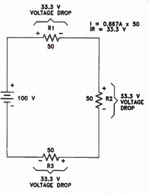
Figure 10. Voltage drops in a series circuit.
You can easily verify this relationship by making the complete current and voltage drop calculations. The total resistance in the circuit is 150 ohms, so the series circuit current is 100 V divided by 150 ohms, or 0.667 amperes. When you multiply the current by the value of resistance to find the voltage drop (using Ohm's law) you find that each resistor has a voltage drop equal to 50 ohms multiplied by 0.667 A, or 33.3 volts.
Unfortunately, circuits will rarely be as simple as those in this example. Suppose the resistors are of unequal value: R1 = 20 ohms, R2 = 30 ohms, and R3 = 50 ohms, like in Fig.11. Add up the total resistance in the circuit (20 + 30 + 50) to get 100 ohms. By itself, R1 is 20/100, or 20% (0.2) of the total resistance. Therefore, the voltage drop across R1 is equal to 20% of the total voltage (0.2 x 100 = 20 volts). Coincidentally, the numbers come out to round figures in the above example. But, the calculation works for odd numbers as well. Suppose that the resistors in the circuit are more realistic:
R1 = 220 ohms, R2 = 470 ohms, and R3 = 1800 ohms.
By adding up the total resistance (220 + 470 + 1800), you get 2490 ohms total. Divide R1 (220 ohms) by 2490 to get 8.8 percent. R2 (470 ohms) accounts for 18.9% of the total; the largest resistor, R3 (1800 ohms), accounts for 72.3% of the source voltage.
Given a source voltage of 100 V, the voltages would be 8.8 V across R1, 18.8 V across R2, and 72.3 V across R3. If the source voltage is changed to 150 V, as shown in Fig.12, we can find the voltage drop across each resistor by simply taking its percentage of the source voltage. In this case, that would be 150 x 0.088, or 13.2 V across R1, 150 x 0.188, or 28.2 V across R2, and 150 x 0.723, or 108.4 V across R3.
Series-Dropping Resistors
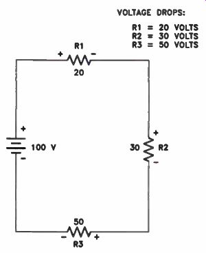
Figure 11. Voltage divider action.
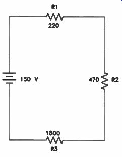
Figure 12. A possible voltage divider arrangement.
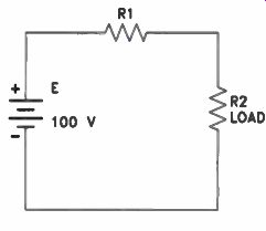
Figure 13. The series-dropping resistor R1 is used to drop the battery
voltage to 50 V for the load R2.
In the circuit shown in Fig.13, on page 12, the source voltage is a 100 V battery, and R2 is the load. Let's assume that the load requires an operating voltage of 50 volts. This means that R1, the series-dropping resistor, must reduce the voltage applied to R2 to 50 volts. We know that current flowing through R1 produces a voltage drop across it, so we must select a value for R1 that will drop enough voltage to leave 50V across
R2. With a source voltage of 100 V, this means that R1 must drop 50 volts.
In this case, since each resistance drops 50 V, R1 and R2 will be equal. However, this isn't always the case. When the voltage drops are unequal, you need to know the load resistance and the voltage it requires. You can then use Ohm's law (I = E/R) to find the current flow in the circuit. The difference between the source voltage and the voltage required by the load is the voltage that must be dropped by R1. To find the resistance of R1, use Ohm's law in the following form: Assume R2 has a resistance of 5000 ohms, with 50 V across it. The current through R2 is: 50 I = 5000 - 0.01 A To find the resistance of R1, subtract the 50 V required by R2 from the source voltage of 100 volts.
The voltage across R1 must be 50 V:
E 50 =I 0.01 - 5000 ohms 12
What happens if the resistance of the load (R2) changes?
Suppose the resistance of R2 varies by as much as 2500 ohms, as in Fig.14. The resistance of R2 can go as low as 2500 ohms, or as high as 7500 ohms. We show this range of resistances by writing 5000 + /- 2500 and saying "five thousand plus or minus twenty-five hundred." If the resistance of R2 drops to 2500 ohms, the total resistance in the circuit made up of R1 and R2 is only 7500 ohms. The total current flow increases to:
100 I = = 0.013 A 7500
This changes the voltage drop across R1 to:
E = 0.013 x 5000 = 65 V
Subtracting this from 100 V leaves only 35 V across R2.
If the resistance of R2 increases to 7500 ohms, the total resistance in the circuit is 12,500 ohms.
The total current flow in the circuit drops to 0.008 amperes. Now the voltage drop across R1 is: E = 0.008 x 5000 = 40 V
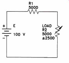
Figure 14. When the values of R2 vary, the voltage across it will vary.
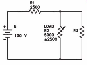
Figure 15. Adding a bleeder resistor, R3, in parallel to R2, will help
stabilize the voltage across R2.
All of this means that one series-dropping resistor is not particularly effective as a voltage regulator. Under the conditions given, the voltage applied to the load, R2, can change from 35 V up to 60 V as the resistance of R2 changes.
By adding a third resistor, called a bleeder resistor, in parallel with R2, we can take a step closer to stabilizing the voltage across R2.
Bleeder Resistors
Figure 15 shows the same 100 V source, and R2 as the load with a nominal resistance of 5000 ohms. We've added a third resistor, R3, which also has a value of 5000 ohms. We know that two equal-value resistors connected in parallel have one-half the resistance of one, so the resistance of R2 and R3 in parallel is 2500 ohms. We want a voltage drop of 50 V across the two-resistor network, so we expect the combined current in the parallel pair to be 50 divided by 2500, or 20 milliamps (I = E/R). That 20 mA flows through R1 in series, and R1 drops the remaining 50 volts. So, the value of R1 must be 50 V divided by 0.02 A, or 2500 ohms (R = E/I). Let's see what happens when the value of R2 changes. Suppose R2 drops to 2500 ohms. This causes the combined resistance of R2 and R3 in parallel to drop to 1667 ohms. The total resistance in the circuit (consisting of R1 in series with the parallel combination of R2 and R3) drops to 4167 ohms. Current flow in the circuit increases from 0.02 to 0.024 ampere.
If the current flow through R1 increases from 0.02A to 0.024A, its voltage drop increases from 50 to 60 volts. The voltage across the load drops to 40 volts. Remember that in the first example, before R3 was added, the voltage dropped to 35 volts. Here we have a change of 10 V, as opposed to a change of 15 volts.
Suppose R2 increases to 7500 ohms. The parallel resistance of R2 and R3 will be 3000 ohms, and the total resistance in the circuit is 5500 ohms. With a source voltage of 100 V, the current flow in the circuit decreases to 0.018 A, the voltage drop across R1 drops to approximately 45.5 V, and the voltage drop across the load to 54.5 volts. Remember that in the last case, before we added R3, the voltage drop across the load climbed to 60 volts. The addition of the bleeder resistor has stabilized the voltage across the load to a significant degree.
The addition of a bleeder resistor increases the current through R1, allowing the use of a smaller series-dropping resistor. Changes in load current, therefore, have less effect on the voltage drop across the series resistor and the voltage across the load remains more constant. The greater the current through the bleeder resistor (that is, the smaller the resistor), the greater the voltage-stabilizing effect. However, since the current through the bleeder is wasted current, a compromise between voltage stability and power lost in the bleeder is generally reached.
At one time, bleeder resistors were widely used in electronics applications to stabilize the voltage in various circuits. They are still found in electronic equipment, but usually for a different purpose, as you will learn later. There are better and more economical ways to maintain a constant voltage in modern equipment.
Review
Resistors can be used to establish fixed voltages in a series circuit. Their values can be calculated easily by following the principle of voltage division, where the voltage drop across each resistor is directly proportional to the relative value of that resistor with respect to the source voltage.
Resistors are often used to drop a voltage from a power source to a lower value needed in a circuit. Bleeder resistors are used across a load through which the current varies to stabilize the voltage across the load. Bleeders were widely used for this purpose, but now there are better devices available and bleeders are used less often.
Self-Test Questions
15. In a series circuit containing 10-, 20-, and , 30-ohm resistors, what is the voltage drop across each resistor if the source voltage is 30 volts?
16. Determine the voltage drops of the circuit shown in Fig.12 by using Ohm's law to calculate the circuit current first. Do these figures correspond with the percentage values listed in the text above (8.8%, 18.9%, and 72.3%)?
17. What is a series-dropping resistor used for?
18. What is the purpose of the bleeder?
19. Which type of bleeder is more effective, a high-resistance bleeder that draws very little current, or a low-resistance bleeder that draws a substantial current?
20. If a load that requires an operating voltage of 60 V is to be operated from a 150 V source, what voltage must the series-dropping resistor drop?
21. If, in the preceding example, the resistance of the load is 1200 ohms, what should the resistance of the series-dropping resistor be?
--------------------
ANSWERS TO SELF-TEST QUESTIONS
1. 4.7k is equal to 4700 ohms.
2. 0.39 M equals 390k, and 390,000 ohms.
3. 680,000 ohms equals 680k, or 0.68 M.
4. The resistor is within its rated tolerance. A 2200 resistor with a tolerance of 10% may vary as much as 220 ohms above or below its indicated value. Subtracting 220 from 2200 gives 1980 as the lowest limit of the resistor.
Since 2000 ohms is between this lower limit and the indicated value of the resistor, the resistor is within tolerance.
5. The resistor may have a resistance of 10,500 ohms. Five percent of 10,000 ohms is 500 ohms.
Therefore, the maximum value the resistor can have and still be within tolerance is 10,500 ohms.
6. 390,000 ohms, or 390k. The tolerance is 5%.
7. 1,000,000, ohms or 1 M. The tolerance is 10%.
8. 56,000 ohms, or 56k. The tolerance is 5%.
9. 2200 ohms, or 2.2k. The tolerance is 10%.
10. Yes, the 1/2% resistor has a closer tolerance than the 1% resistor. It is a better resistor.
You can always use a better resistor, one with a closer tolerance, as a replacement.
11. When we say a resistor is dissipating 10 W, we mean that the resistor is using 10 W of electrical energy. We say it is dissipating the power because it changes the power from electrical energy to heat.
12. 10 watts. To rind the power dissipated by the resistor we use the formula: E2 Substitute 100 for E and 1000 for R: 100 x 100 P = 1000 (Canceling three Os above the line and three Os below the line gives you P = 10 watts.)
13. 1/2 watt. To solve the problem use the formula: p E2 4 = R Substitute 50 V for E and 5000 ohms for R: 50 x 50 P = 5000 2500 _ 5000 1 - - w 2
14. 100 watts.
To solve the problem use the formula: P = I^2R
Substitute 2 for I and 25 for R: P = 2 x 2 x 25 = 100 W
15. The total resistance is 10 + 20 + 30, or 60 ohms.
For R1, 10 ohms is 10/60, or 1/6, so its voltage drop is 1/6 of the source voltage. One sixth of 30 is 5 volts. R2 equals 20/60, or 1/3; one-third of 30 equals 10 volts. R3 is one-half the total resistance, and drops one-half the total voltage, or 15 volts.
16. The total resistance in the circuit is 2490 ohms (220 + 470 + 1800). Current is E/R, or 150/2490, which equals 0.060 amperes.
Multiplying 0.060 by 220, 470, and 1800 produces voltage drop figures of 13.2 V, 28.3 V, and 108.4 V, respectively. This corresponds with the values that can be determined from the percentage that each resistor represents of the total, by multiplying the percentage represented by the resistor and the value of the source voltage.
17. A series-dropping resistor drops the available voltage to the value required by the load.
18. A bleeder is used to regulate, or to help maintain a constant voltage across the load.
19. A low-resistance bleeder that draws a substantial current is more effective than a high- resistance bleeder that draws only a small current.
20. 90 volts.
21. 1800 ohms.
60 I = 1200 = 0.05 A
The value of the series-dropping resistor can be found using the formula: E R = - 90
0.05 = 1800 ohms
-------------
Lesson Summary
Some of the important facts you should remember about this letter are:
• Resistors are available in many values, wattage ratings, and designs.
• You can identify the value and tolerance of a resistor by reading the color-coded bands on its body.
• Resistors determine the currents in an electronic circuit, and therefore determine most of the voltage drops.
• A bleeder resistor can help stabilize a source voltage, but uses some circuit current unproductively.
LESSON QUESTIONS
This is Lesson Number 2221.
Make sure you print your name, student number, and lesson number in the space provided on the Les son Answer Form. Be sure to fill in the circles beneath your student number and lesson number.
Reminder: A properly completed Lesson Answer Form allows us to evaluate your answers and speed the results and additional study material to you as soon as possible. Do not hold your Lesson Answer Forms to send several at one time. You may run out of study material if you do not send your answers for evaluation promptly.
1. Three important types of resistors are: Carbon, metal-oxide, and wire-wound resistors.
b. 1/2 W, 1 W, and 2 W resistors.
c. 1%, 5%, and 10% resistors.
d. Ohm, kilohm, and megohm resistors.
2. A resistor that is color-coded green, blue, orange, and gold has a resistance and tolerance of:
a. 56,000 ohms, 5 percent.
b. 6500 ohms, 5 percent.
c. 6500 ohms, 10 percent.
d. 56,000 ohms, 10 percent.
3. A resistor that is color-coded gray, red, red, and gold has a resistance and tolerance of: 8200 ohms, 5 percent.
b. 8500 ohms, 10 percent.
c. 8500 ohms, 5 percent.
d. 850 ohms, 5 percent.
4. Most of the carbon resistors found in a video cassette recorder or in a microcomputer are:
a. 1/4 or 1 watt.
b. 1/2 or 1 watt.
c. 1 or 2 watts.
d. 1/4 or 1/2 watt.
5. If the voltage across a 5000-ohm resistor is 100 v how much power is the resistor dissipating?
a. 100 watts.
b. 50 watts.
c. 10 watts.
d. 2 watts.
6. In a series circuit containing four resistors 100, 200, 300, and 400 ohms, what is the voltage across the 400-ohm resistor if the applied source voltage is 50 volts?
a. 5 volts.
b. 10 volts.
c. 15 volts.
d. 20 volts.
7. What are the color-code bands of a 120-ohm, 5% resistor?
a. Brown, red, black, and gold.
b. Black, red, black, and silver.
c. Brown, red, brown, and gold.
d. Black, red, brown, and gold.
8. What are the color-code bands of a 47,000-ohm, 10% resistor?
a. Yellow, purple, orange, and gold.
b. Yellow, purple, orange, and silver.
c. Yellow, purple, red, and gold.
d. Yellow, purple, yellow, and gold.
9. A 750-ohm load must be operated with a voltage of 75 volts. The available voltage is 125 volts. What value of series-dropping resistor should be used to drop the voltage?
a. 250 ohms.
b. 500 ohms.
c. 750 ohms.
d. 1000 ohms.
10. The resistance of a thermistor:
a. Increases as the voltage increases.
b. Decreases as the temperature increases.
c. Increases as the temperature increases.
d. Decreases as the voltage decreases.
-----------------
NRI--HELP YOUR MEMORY
Experience is a great teacher, providing you have a great memory! Even if you don't have a good memory, there are things that you can do to make the most of the one you have. An unusual design or production problem may take you hours to figure out the first time you encounter it - but the next time, you should be able to solve the problem in a flash. Unfortunately, that next time may not occur for several months; by then you may have completely forgotten what you did the first time.
You can aid your memory by keeping notes. Every time you encounter a difficult situation, write up a careful and complete description of it and how you corrected the problem.
After collecting this information, you'll never use it if you don't organize it and keep it close to your work area. Use a file system or a notebook to arrange your notes by project name or topic. In time, you will have a valuable storehouse of troubleshooting information - such as only you can collect!
---------------------------