AMAZON multi-meters discounts AMAZON oscilloscope discounts
Table of Contents:
- Introduction
- Characteristics of Coils
- How Coils Produce Voltage
- Lenz's Law for Coils
- Methods of Changing Flux Linkages
- Review
- Self-Test Questions
- Inductance
- Self-Induced Voltages
- Units of Inductance
- Factors Affecting Inductance
- Inductive Reactance
- Mutual Inductance
- Review
- Self-Test Questions
- Applying Ohm's Law to Coils
- Phase
- Impedance
- Finding the Current in an AC Circuit
- The Q of a Coil
- Review
- Self-Test Questions
- Answers to Self-Test Questions
- Lesson Questions
-----------------------
Lesson Objectives:
In this lesson you will...
• Discover how coils and magnets can produce voltage and current.
• Learn Lenz's Law for coils.
• Be introduced to the properties of inductance.
• Examine how inductance affects inductive reactance.
• Learn how inductance and resistance combine to form impedance.
• Learn about the effects of inductance on the current and voltage phases in an electronic circuit.
INTRODUCTION
You will look at inductance in this lesson, and you will discover how it relates to electromotive force. Inductance is an interesting phenomenon which continues to be studied and explored.
Each electron in an electric current creates a small magnetic field when it moves. A current, which consists simply of many moving electrons, creates a larger magnetic field that is the sum of all the fields of the individual moving electrons.
The magnetic field and the current are firmly interrelated. If either is changed, the other will also change.
In this lesson you will learn how inductance affects de circuits and how it opposes current in an AC circuit. You will also learn about the factors that affect inductance and how inductors affect circuit behavior.
-------------
CHARACTERISTICS OF COILS
Coils are important components in many electronic circuits. Almost every piece of electronic equipment has one or more coils in it.
You will see coils of one or two turns, and even hundreds - or thousands - of turns. Coils that are self-supporting and contain only air and coils wound on a nmagnatic_material (such as cardboard) are called air-core mils. Coils that are wound on a _magnetic material (such as iron or steel) are called iron-core coils.
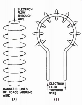
Figure 1. (A) When current flows through a wire, magnetic lines of force
are set up around the wire. (B) When the wire is bent into a loop, the
lines of force all go through the loop in the same direction.
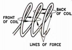
Figure 2. Lines of force loop around both turns of the coll.
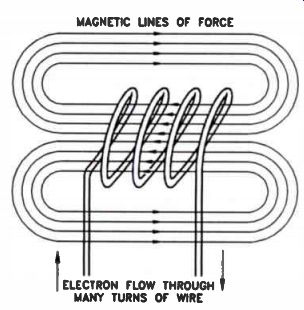
Figure 3. Magnetic lines of force form complete loops, passing through
and around the coil.
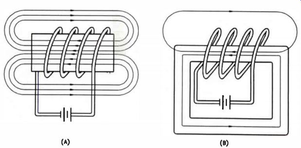
Figure 4. (A) Inserting an iron core in a coil reduces the reluctance
and increases the number of magnetic lines of force. (B) A complete iron
core reduces the reluctance still further.
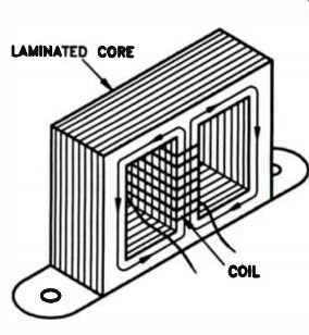
Figure 5. Iron cores have a greater flux than air cores.
You already know that when current flows through a wire there is a magnetic field created around the wire. As Fig.1(A) shows, this field is made up of circular magnetic lines of force (flux) around the wire. The field is much stronger closer to the wire than it is at a distance. When the wire is bent into the form of a loop, as shown in Fig.1(B), all the magnetic lines of force go through the loop in the same direction. This tends to concentrate the magnetic lines of force and produce a much stronger magnetic field.
In the 2-turn coil shown in Fig.2, the magnetic lines of force loop around both turns of the coil.
This field can be made stronger by winding even more turns on the coil, as shown in Fig.3. Here you can see that the magnetic lines of force go through the coil and then separate, some flowing around one side of the coil and some flowing around the other side. Notice that the magnetic lines of force are complete loops flowing through the entire center of the coil, around one side, and then back through the center of the coil.
Like the resistance to electric current found in conductors, magnetic lines of force flowing around a coil encounter opposition to the magnetic field. …. reluctance.
We can reduce the reluctance in a magnetic circuit by placing an iron core inside the coil, as shown in Fig.4(A). Iron has much lower reluctance than air, and tends to concentrate and strengthen the magnetic field. The magnetic lines of force leaving the end of the core still flow through the air.
By using a core such as the one shown in Fig.4(B), this reluctance can be further reduced by providing a complete magnetic path for the lines of force.
However, this is not a complete solution. Because the lines of force flow in loops in both directions, some of the lines of force will continue to flow through the air. By constructing a core as shown in Fig.5, we can establish a complete magnetic path around both sides of the coil, and minimize reluctance.
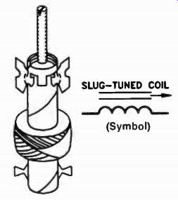
Figure 6. A slug-tuned coil and its schematic symbol.
Iron-core coils work best at low frequencies.
Coils used at high frequencies have either an air core or a ferrite core such as the one shown in Fig.6. This coil is wound on a cardboard form with an adjustable ferrite core inside. The core, or "slug," can move in and out of the coil by means of a screw-type adjustment at the top. The schematic symbol for this type of coil is shown.
Not all coils of this type have screw adjustments. In some, the ferrite slug is threaded and slotted. It can be screwed in or out of the coil with a nonmagnetic alignment tool. This coil uses the same schematic symbol as the screw type.
Slugs are made of different materials, but ferrite is the most common. Ferrite has very high magnetic permeability …. magnetization. Its is made of powdered iron with other mifèfiIs such as manigarjie- , cobalt, nickel, or zinc added to give the desired permeability. These materials are mixed together, then fired at a high temperature. When they cool they form a solid slug. The permeability of the material depends upon the materials used.
Electric circuits have an electromotive force or voltage that causes current to flow. An electro magnetic circuit Ilas a magnetomotive force that _ produces neti . This magnetomotive force is measured in ampere-turns. If a coil has 1 turn and the current flowing through it is 1 A, the magnetomotive force is 1 ampere-turn. If the coil has 2 turns and 1A, it has 2 ampere-turns.
If it has 10 turns, it is 10 ampere-turns. If the 10-turn coil has 2A flowing through it, the magnetomotive force is 20 ampere-turns.
The equivalent of current in magnetic circuits is the magnetic lines of force, or magnetic flux; the more magnetic lines of force there are, the greater the magnetic flux. The number of magnetic lines of force produced depends upon the magnetomotive force. The higher the magnetomotive force, the greater the number of magnetic lines of force, and the greater the flux density. Flux density also depends upon the reluctance or resistance to the magnetic lines of force. The lower the reluctance, the greater the flux.
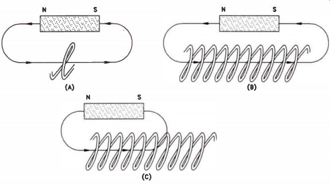
Figure 7. How the number of flux linkages can be changed. (A) There
is one flux linkage. (B) There are 10 flux linkages. (C) There are six
flux linkages.
Again, note the similarity between the magnetic circuit and the electric circuit. The magnetic circuit essentially follows Ohm's law for electric circuits. If you increase the magnetomotive force, which is the equivalent of voltage, you'll increase the magnetic flux, which is the equivalent of current. If you reduce the reluctance, you'll increase the magnetic flux.
Remember that when we discussed the conductivity of materials, we said that copper is a good conductor of electricity, but silver is even better. Copper is a better conductor than aluminum and iron. Because conductivity of materials varies, wires of the same size and length may have a different resistance, depending on the materials from which they are made.
Similarly, magnetic circuits may have a different reluctance depending on the permeability of the materials in the magnetic path. Permeability in magnetic circuits is the equivalent of conductance in an electrical circuit. We base the permeability of materials on air - …ty-ef--aiti-isene. Magnetic materials have a higher permeability than non-magnetic materials. If the permeability of a material is 20, we can expect 20 times the magnetic flux through this material than there would be through air for the same number of ampere-turns.
Magnetic circuits are important because they can help you understand how coils work. You should remember what is meant by magnetomotive force, magnetic flux, reluctance, and permeability.
How Coils Produce Voltage
It is important that you understand how a voltage can be produced by a coil. To see this, you must first learn something about flux and flux linkages, and then see how changing the flux linkages of a coil will produce a voltage in the coil.
Flux Linkages. Suppose you have a magnet that produces a single magnetic line of force. If the magnet is brought near a coil having one turn, such as that shown in Fig.7(A), there will be one magnetic line linking with (or passing through) the one-turn coil, and there will be one flux linkage. If there were 10 turns on the coil and one line of force passed through all 10 turns, then there would be 10 flux linkages, as shown in Fig.7(B). In turn, if the single magnetic line passed through and linked only 6 turns of the 10-turn coil, as shown in Fig.7(C), there would be only 6 flux linkages. Flux linkage tells us how many magnetic lines of force pass through and "link" the turns of a coil. If we have a magnet that produces 100 magnetic lines, and if the entire 100 lines are linked to a coil having 80 turns, the number of flux linkages is 80 x 100, or 8000 flux linkages.
Figure 8(A) shows a magnet with 10 magnetic lines of force, but only two of them cut through all 5 turns of the coil. Consequently, there is a total of 10 flux linkages. As you can see, part of the flux is lost, because not all of the lines of fore cut through the coil. This is called flux leakage.
If we move the magnet to …own in Fig.8(B), so that the magnet is placed inside the coil and all 10 lines cut through the 5 turns of the coil, there is a total of 50 flux linkages.
When the number of flux linkages increases from 10 to 50, a voltage is produced in the coil as the magnet moves This voltage, as you know, is called induced voltage. If the magnet is moved away from the coil so that the number of flux linkages decreases, a voltage is again induced in the coil as the magnet moves.
In each of these cases there is a change of 40 flux linkages. If we have a stronger magnet so that the number of lines of force is greater, and therefore the change in flux linkages is greater, a larger voltage is induced in the coil.
By moving the magnet either toward or away from the coil, there is a voltage induced in the coil that is affected by the speed with which the magnet is moved. If the magnet is moved slowly so that the number of flux linkages changes slowly, the voltage induced in the coil is small.
However, if the magnet is moved rapidly so that the change in flux linkage occurs very quickly, the voltage induced is higher. In other words, the í th voltage induced in the coil depends not only on e change in flux linkages, but also upon the speed with which the change occurs. Basically, this is another way of stating that the voltage induced depends upon the number of lines of force that "cut" the windings of the coil in a unit of time. The faster the change occurs, the higher the induced voltage.
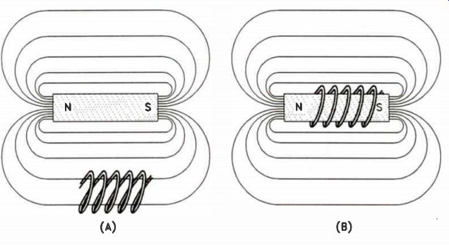
Figure 8. (A) There are 10 flux linkages with the magnet outside of
the coil. (B) There are 50 flux linkages when the magnet is moved inside
the coil.
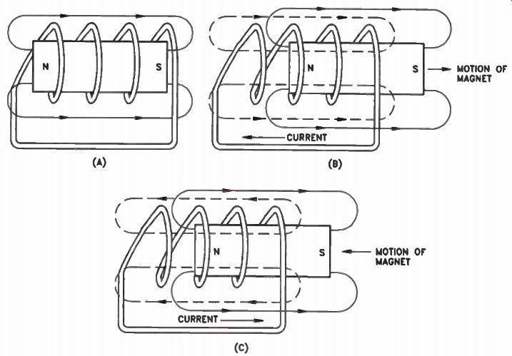
Figure 9. Changing the number of flux linkages induces a voltage in
the coil. The polarity of the voltage depends upon whether the number
of flux linkages is increasing or decreasing. (A) Eight flux linkages.
(B) As the magnet is moved away, the number of flux linkages changes.
(C) As the magnet moves back into the coil a voltage is induced.
Lenz's Law for Coils
The polarity of the voltage induced in a coil depends on the direction of the flux and whether the flux linkages are increasing or decreasing.
This relationship is known as Lenz's law, named after the man who discovered it.
Voltage is induced when the number of flux linkages cutting a coil changes. If the circuit is complete, this induced voltage sends a current through the coil. This current opposes the change in the magnetic flux. If the flux linkages are increasing, the magnetic flux produced by the current in the coil opposes the increase. If the flux linkages are decreasing, the magnetic flux produced by the current in the coil opposes the decrease.
This is an important concept, and may be better understood by referring to the circuit shown in Fig.9. In Fig.9(A), there is a magnetic circuit with two flux lines cutting through a 4-turn coil, which creates 8 flux linkages. As the magnet is moved away from the coil, reducing the number of flux linkages, shown in Fig.9(B), a voltage is induced in the coil and current flows. The current flowing in the coil creates another magnetic field which aids the flux linkages already existing. In other words, it tries to maintain the original eight flux linkages. As long as the number of flux lines are changing, the induced voltage causes an induced current that produces flux lines as shown.
If the magnet is moved back into the coil, as shown in Fig.9(C), the number of flux linkages increases. However, a voltage is induced in the coil that causes a current to flow in the opposite direction, and set up its own flux lines of force to oppose the increasing flux lines from the magnet.
If the number of flux linkages is decreasing, the induced voltage has a polarity that causes a current flow to oppose this decrease in flux linkages. In turn, if the flux linkages are increasing, the induced voltage will have a polarity that causes the current to flow to oppose this increase in flux linkages.
If this sounds to you like the induced current creates a field that fights against the action of the magnetic field that started the whole process, this is essentially what happens.
Remember, electrical energy does not spring from nowhere. In this case, the motion of the magnet is a physical energy input which is being converted into electrical energy by the effect of the magnetic field upon the coiled conductor. The currents and the fields act as a load upon the physical movement of the magnet or coil (whichever is being made to move), and that load is expressed as opposing fields.
Methods of Changing Flux Linkages
There are three methods of producing changes in flux linkages in a coil: moving the coil or the magnet, changing the reluctance, or changing the current flowing in the coil.
Motion. You know that when a conductor moves through a magnetic field, it cuts the magnetic lines of force so that a voltage is induced in the conductor. In a generator, for instance, as the coil rotates it moves through and cuts the magnetic lines of force produced by a magnet. The voltage induced creates a current if an external circuit is present. Current flowing in that external circuit creates a field around the coil that opposes the change in the original flux linkages, producing the voltage.
Changing the Reluctance. Any change in the reluctance of the material in the magnetic field will change the amount of flux that passes through the coil, thus changing the flux linkages through the coil and inducing a voltage. Remember: a voltage is induced whenever there is a change in flux linkages.
Changing the Coil Current. Transformers used on AC power lines are an example of how a changing coil current is used to produce a voltage. You should remember that the voltage on an AC power line is constantly varying from zero up to peak with one polarity, back to zero, to a peak with the opposite polarity, and then back to zero.
As shown in Fig.10(A), a transformer is made by winding two or more coils on a single core.
When the first winding of the transformer, the primary winding, is plugged into the AC power line, the varying voltage across it will cause a varying current to flow through this winding.
The varying current through the primary winding will produce magnetic flux that is constantly changing.
This changing flux induces a voltage in the other winding on the transformer, called the secondary winding. The voltage induced in the secondary winding depends upon the ratio of the primary turns to the secondary turns.
If both windings have the same number of turns, the voltage induced in the secondary winding is equal to the voltage applied to the primary winding. If the secondary winding has twice as many turns, the voltage induced is twice the voltage applied to the primary winding. This type of transformer is called a step-up transformer. If the secondary winding has only half as many turns as the primary winding, the voltage induced in the secondary is equal to half the voltage applied to the primary. This type or transformer is called a step-down transformer.
The schematic symbol for a transformer having two windings is shown in Fig.10(B). Figure 10(C) is the schematic symbol of a transformer with two secondary windings. In this case, one winding has more turns than the primary, so it is a step-up secondary winding; the other secondary winding has fewer turns than the primary, so it is a step-down secondary winding. You will learn more about transformers in a later lesson when you study power supplies.
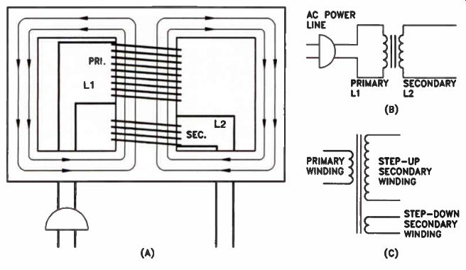
Figure 10. A power transformer. (A) The primary winding is connected
directly to the power line. As the current through the primary winding
varies, the flux produced by L1 will vary, resulting in a change in flux
linkages through the secondary winding, inducing a voltage in the secondary
winding L1. (B) The schematic symbol for one primary and one secondary
winding. (C) The schematic symbol for one primary and two secondary windings.
Review
There are several important facts that you should remember from this section of the lesson.
Remember that a voltage is induced in a coil when the number of flux linkages changes.
Either an increase or a decrease in the number of flux linkages will induce a voltage in the coil.
Remember Lenz's law. It states that the induced voltage always acts in such a direction that it tends to oppose the original change in flux linkages.
Changes in flux linkages can be produced by cutting through magnetic lines of force, by changing the reluctance in the magnetic circuit, or by changing the current flowing through the circuit.
Self-Test Questions
1 What type of a coil is wound on a cardboard form?
2 What purpose does an iron core serve in a coil?
3 What is magnetomotive force?
4 What is the unit used to measure magneto motive force?
5 If the current flow through a 25-turn coil is 2 A, how many ampere-turns are produced?
6 What is reluctance?
7 Does the magnetic circuit in an air-core coil have a higher reluctance than an iron-core coil?
8 What is permeability?
9 What is the relationship between flux, magnetomotive force, and reluctance?
10 What are flux linkages?
11 If three magnetic lines of flux cut through four turns of a coil, how many flux linkages are there?
12 If 100 flux linkages cut through a coil, and this number of flux linkages does not change, what will the voltage induced in the coil be?
13 According to Lenz's law, if there is a change in the number of flux linkages cutting a coil, induced voltage produces a current. Does the magnetic flux produced by the current aid or oppose the change in flux linkages?
14 When the number of flux linkages cutting a coil is reduced, will the field produced by the induced voltage aid or oppose the original lines of force?
15 List three methods of changing flux link ages.
------------
INDUCTANCE
The property of a coil that determines the voltage induced in the coil is called inductance.
The inductance of a coil depends upon the number of turns of wire on the coil, and upon the permeability of the material. Saying that a coil has inductance is as obvious as saying a resistor has resistance. Inductance is a basic property of coils; it indicates how much voltage is induced in a coil for a given change in flux linkages.
Self-Induced Voltages
If a voltage is connected to a coil, current will flow through the coil and set up a magnetic field.
As Fig.11 illustrates, the magnetic field will produce lines of flux around the coil.
If the current flowing through the coil is suddenly changed, the magnetic field generated by the current also changes. This changes the number of flux linkages produced, and therefore passing through, the turns of the coil. The change in flux linkages within the coil itself (caused by either an increase or decrease in circuit current) induces a voltage in the coil. In accordance with Lenz's law, this voltage opposes the change and causes a current to flow in such a direction as to produce a magnetic field that opposes the change in the magnetic field. The voltage induced in this manner is known as a self-induced voltage.
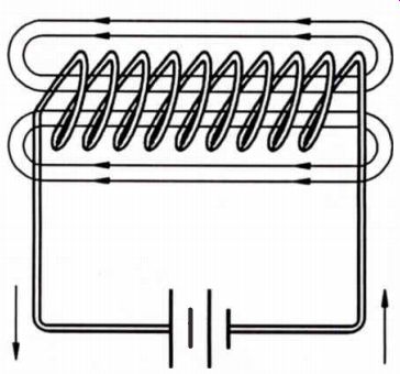
Figure 11. If a voltage source Is connected to a coil, current will
flow through the coil and a magnetic field will be set up.
Units of Inductance
For a given change in flux linkages, the voltage that is induced in a coil depends upon the inductance of the coil. The unit of inductance is the henry, abbreviated H. It is named after Joseph Henry, a scientist who did a great deal of experimentation with coils. A coil will have an inductance of 1 H if a current change of 1 A per second will induce a voltage of 1 V in the coil.
Some iron-core coils used in electronics have an inductance of 10, 20, or perhaps as high as 30 henrys. Most air-core coils, however, have a very small inductance. For convenience, just as the ampere can be broken down into mA and µA, the henry can be broken down into millihenrys (mH) and microhenrys (uH). A millihenry is a thousandth of a henry and a microhenry is a millionth of a henry.
To convert henrys to millihenrys (like converting amperes to milliamperes), just move the decimal point three places to the right. To convert from millihenrys to henrys, move the decimal point three places to the left. To convert henrys to microhenrys, move the decimal point six places to the right, and to convert from microhenrys to henrys, move the decimal point six places to the left. To convert from millihenrys to microhenrys, move the decimal point three places to the right, and to convert from microhenrys to millihenrys, move the decimal point three places to the left.
Factors Affecting Inductance
The inductance of a coil is affected by the number of turns on the coil. A coil having 200 turns will have a higher inductance than a coil having 100 turns on the same type of core.
Inductance is also affected by the shape and size of the coil. A long coil that has considerable space between the turns will have a lower inductance than a short coil with the same number of turns closer together. The reason for this is that in a coil with more space between turns, many of the lines of flux will escape after cutting through only a few turns of the coil. This results in flux leakage.
The diameter of a coil also affects the inductance in the coil. A coil with a large diameter will have a higher inductance than one with a smaller diameter and the same number of turns.
The inductance of a coil is also affected by the core material. A core material with a high permeability will produce more flux, and therefore more flux linkages. The higher the permeability of the core material, the greater the inductance.
Inductance is not limited to coils alone. Wire wound resistors have inductance. As a matter of fact, even a straight piece of wire has some inductance, because when a current flows through a wire, a magnetic field is set up around the wire and the wire is cut by magnetic lines.
The inductance of a short piece of straight wire is very low (only a fraction of a microhenry), but in some circuits operating at very high frequencies even this small amount may be important.
Because the most important property of a coil is inductance, coils are often called inductors or inductances. Remember these terms - you will see them often.
Inductive Reactance
If we connect an iron-core coil across a battery as shown in Fig.12(A), current will flow. When the switch closes, the current that flows produces an increasing magnetic field. That field, in turn, induces a voltage in the coil that opposes the current. However, the induced voltage is not great enough to prevent the current from reaching its maximum value, which is limited only by the de resistance of the coil wire.
When the current reaches its maximum value the magnetic field no longer changes, and subsequently, no more opposing voltage is induced in the coil.
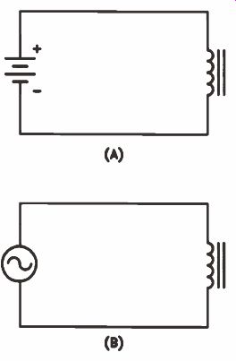
Figure 12. (A) A coil connected to a battery, and (B) to an AC generator.
In connecting the same coil across a 60 Hz AC generator, as shown in Fig.12(B), there is an entirely different effect. As the voltage from the generator increases, current increases in the coil. This generates a changing flux which induces a voltage in the coil that opposes the increase in current. When the AC voltage reaches its maximum value and begins to decrease, the current and the magnetic field (and hence the flux) also start to decrease. When this happens, a voltage will be induced in the coil which op poses this change, aiding the existing field.
This induced voltage is called a counter electromotive force, which is abbreviated cemf. In effect, this c_emf subtracts from the applied voltage so that there is considerable opposition to the flow of AC through the coil. This opposition is called reactance, and since it is produced by an inductor, it is called inductive reactance.
We use the letter L to represent inductance, the letter f to represent frequency, and the letter X to represent reactance. When we want to indicate that the reactance is inductive reactance, we use a subscript L with an uppercase X. The formula for the inductive reactance of a coil is: XL = 2nfL You can see from this formula that inductive reactance varies directly with frequency. If you double the frequency of the AC applied to the coil, the inductive reactance will also double. Similarly, the inductive reactance varies in direct proportion to the inductance of the coil.
You have probably seen the Greek letter pi (pronounced pie) before. It is used for finding the area of a circle. The value of sr is approximately 3.14, so 2-pi has a value of 6.28. You will often see the formula for inductive reactance written: XL = 6.28fL (The multiplication signs are frequently omitted for convenience, but the formula actually means 6.28 x f x L.) Now you can get a better idea of how the inductive reactance of a coil limits the current through the coil. A 1 H coil might have a DC resistance of 25-30 ohms. Let's assume it is 30 ohms. If we connect that coil across a 120 V DC power line, a current of 4 A will flow through the coil. However, using the formula for inductive reactance, the same coil, when connected across a 60 Hz power line, will have an inductive reactance of: XL = 6.28 x 60 x1 = 377 ohms If we connect this coil across a 120 V, 60 Hz power line, the inductive reactance alone would limit the current to 0.32 ampere.
Mutual Inductance
When two coils are placed close together so that the field from one coil cuts the turns on the other, a changing field in the one coil will induce a voltage in the other. We call this mutual inductance and it is represented by the letter M. Mutual inductance may be either aiding or op posing, depending upon whether the two fields aid or oppose each other.
If two coils are connected in series, but are far enough apart that their fields do not interact, the total inductance will be equal to the sum of their individual inductances. In other words:
L T = L1 + L2
If two coils are placed so that their fields interact and they are connected in series, the mutual inductance between the coils enters into the total inductance. If the coils are connected so that their fields aid, the total inductance be comes:
L T = L1 + L2 + 2M
If they are connected so that their fields oppose, the total inductance becomes: L T = L1 + L2 - 2M
When coils are connected in parallel, the effect is similar to resistors connected in parallel. This is easy to see if you look at Fig.13. Coils L 1 and L2 are connected in parallel across a 120 V AC generator. If we assume that each coil has an inductive reactance of 120 ohms, there is a current of 1 A flowing through each one, with a total current flow of 2 amperes.
In this example, since the total current is twice what it is through either coil, the combination must have only half the inductive reactance.
This means that the total inductance in the circuit must be only half the inductance of either coil. If we connect a third coil in parallel, the total inductance is only one-third the inductance of each individual coil.
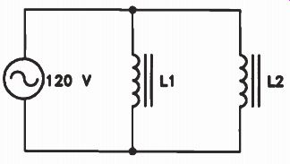
Figure 13. Coils connected in parallel act like resistors connected
in parallel. The total inductance is less than the inductance of the
smallest coil.
Review Inductance
is the electrical property that describes coils, and the unit of inductance is the henry. When a current flowing through a coil changes, there is a voltage induced in the coil that opposes the change that produces it. This voltage is a self-induced voltage and is called counter electromotive force, abbreviated c_emf.
Inductive reactance is the opposition that a coil offers to the flow of AC through it. Inductive reactance is measured in ohms, and is similar to resistance because it opposes the flow of AC through the coil.
When coils are connected in series, the total inductance is the sum of the individual inductances. If they are connected in series and there is mutual coupling between the two, the mutual coupling may either add to the total inductance or subtract from it, depending on whether the fields aid or oppose each other. When coils are connected in parallel, they act like resistors in parallel, so that the total inductance is less than the inductance of the smallest coil.
Self-Test Questions
16 What is the property of a coil that will deter mine the voltage induced in it?
17 If the voltage applied to a coil is suddenly increased, will the self-induced voltage produced in the coil aid or oppose the applied voltage?
18 What is the unit used to measure inductance?
19 What are three factors that affect the inductance of a coil?
20 What is the inductive reactance of a coil?
21 What is the unit of measurement for the inductive reactance of a coil?
22 What is the inductive reactance of a 10 H coil at a frequency of 60 hertz?
23 If two coils, one having an inductance of 6 H and the other having an inductance of 8 H, are placed some distance apart so that there is no mutual inductance between them, what is the total inductance of the two coils if they are connected in series?
24 Two coils, one having an inductance of 4 H and the other having an inductance of 3 H, have a mutual inductance of 2 henrys. If the coils are connected in series and are aiding, what will the total inductance be?
25 If an 8 H coil and a 7 H coil that have a mutual inductance of 3 H are connected in series in opposition, what will the total inductance of the two coils be?
26 Convert 2.2 H to millihenrys.
--------------------
APPLYING OHM'S LAW TO COILS
Ohm's law tells us that current in a de circuit depends upon the voltage applied and the resistance in the circuit. This rule applies to AC circuits also, but you must calculate the total opposition to current, which consists of the DC resistance plus any reactance. This composite total opposition to current flow is called impedance and is represented by the letter Z. In this section of the lesson you are going to learn about impedance and about phase - another important aspect of AC circuits.
Phase
Phase is a common term in the study of electronic circuits. The expressions "in phase," "out of phase," and "phase shift" will become very familiar to you.
In a circuit containing only resistance, if we increase the voltage, the current increases immediately - the increase in current follows the voltage changes instantly. In an AC circuit containing only resistance, as the voltage goes through its cycle, the current varies instantaneously as the voltage varies. We say that the current is in phase with the voltage. This simply means that a change in voltage will produce a similar change in the current flow in the circuit at the same instant.
This is not true of circuits containing coils.
Look at the circuit shown in Fig.14. Here we have a resistor and a coil connected in series, and the two are connected across an AC generator.
Let's examine the AC current flowing through the circuit to see what happens to the voltage across the resistor and the coil as the current goes through its cycle.
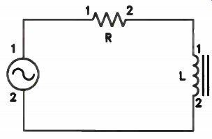
Figure 14. A coil and resistor connected in series across an AC source.
Figure 15(A) shows a single current cycle from the AC generator in Fig.14. The start of the sine wave cycle is marked point A. At the instant the cycle begins at point A, the current is increasing at its maximum rate of change. This occurs at both the upslope and downslope of the AC waveform. The rate of change is greatest during gains or drops in current, and lower (but still changing) around the peaks. At the peaks, the rate of change briefly drops to zero as the direction of current flow reverses.
Consider the voltage across the resistor R. As the current increases from point A to point C, the voltage drop across the resistor increases at exactly the same rate as the current, generating the waveform shown in Fig.15(B). At point C, as the current reaches its maximum value, so will the voltage. As the current reverses direction and goes through the second half of its cycle, the voltage will follow exactly as shown in the waveform. Notice that at each instant in time throughout the entire cycle, the voltage across the resistor is exactly proportional to the current flowing through it. Here the current and voltage are in phase.
The voltage and current across the coil will not be in phase. This is because the voltage across the coil depends upon the rate of flux change.
The maximum flux change occurs when the current is changing at its highest rate. Therefore, since the current is changing at a maximum rate at point A in Fig.15(A), we will have a maximum voltage across the coil. As the current increases from point A to point C, the rate of change decreases until it reaches point C, where it does not change at all, at which point we will see the minimum amount of voltage across the coil.
Remember, this self-induced voltage in the coil opposes the applied voltage from the generator. It is a result of inductive reactance to alternating current in the coil, and is not the same thing as resistive voltage drop. There is a voltage drop across the DC resistance of the coil that may be taken into account if necessary but for the moment we are measuring the reactively induced voltage.
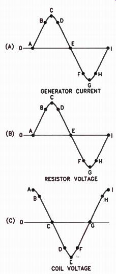
Figure 15. (A) A single current cycle, (B) the resulting voltage drop
across the resistor, and (C) the voltage across the coil.
The voltage across the coil continues to follow the curve shown in Fig.15(C). The induced voltage decreases until, when the current reaches point C, the voltage has dropped to zero. Now as the current begins to decrease, a voltage is induced in the coil that tries to oppose that change.
That is, the voltage builds up from C to a maximum value at E when the current is going through zero and changing at the maximum rate. As the current begins to flow in the opposite direction from E to G, the rate of change once again is decreasing, so the voltage falls from E to G as shown in Fig.15(C). Finally, as the current falls from G to I, where it once again changes at its maximum rate, the coil voltage builds up from G to I, reaching a maximum value once again.
Compare Fig.15(A) to Fig.15(C). In Fig.15(A), from point A to point I is one cycle. It also represents 360°, or a complete circle extended over time (shown graphically). From A to E is a half-cycle (180 degree), and from A to C is a quarter cycle (90°). When the generator current begins its first quarter-cycle increase (from A to C), the induced coil voltage begins to decrease. As generator current peaks, and enters its second quarter-cycle from C to E, once again the coil voltage is a quarter-cycle ahead. This process continues indefinitely. We say that the voltage across the coil leads the current by 90 degrees.
Conversely, we can say that the current lags the voltage by 90°; it means the same thing. In any case, this is an extremely important point for you to remember: in a purely inductive circuit, the current will always lag the voltage by 90 degrees.
None of this changes the fact that current is the same in all parts of a series circuit - that is, the current is the same in the generator, the connecting wires, the resistor, and the coil. The time lag (the phase difference) is between current and voltage in the coil.
What about the phase relationship of the circuit current and voltage? Because of the resistive component in the circuit, the voltage phase must lead the current by some value between 0° and 90°, since the circuit is not purely inductive. Let's assume that the resistance in the circuit of Fig.14 is equal to the inductive reactance of the coil. The voltage developed across the resistor is equal to IR, and the voltage developed across the coil is equal to ' XL (the circuit current times the reactance of the coil). Therefore, the voltage drop across the resistor is equal to the reactive voltage across the coil.
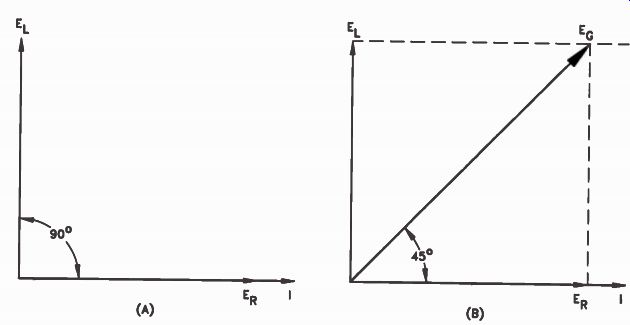
Figure 16. Vector diagrams showing the relationship between circuit
current, generator voltage, coil voltage, and resistor voltage of the
current shown in Figure 15. (A) The vectors for circuit current ( ER)
and coil voltage ( EL). ( B) The generator voltage vector ( EG)-
We can use a vector diagram (shown below) to determine the phase relationship between the generator voltage and current. This is the relationship in the complete circuit, as "seen by" the generator. We start by drawing the vector I as shown as Fig.16(A). The horizontal position of the current vector I is referred to as zero degrees.
Since the voltage across the resistor is in phase with the current through it, we can draw the resistor voltage vector on top of the current vector.
The vector representing the voltage across the coil leads the current by 90 degrees. To diagram this fact, we rotate this vector 90° in a counterclockwise direction. It is the same length as the resistor voltage vector because the two voltages are equal. To find the generator voltage vector, we complete the diagram, as shown in Fig.16(B), by drawing two dotted lines to their junction and completing the generator vector. With the voltage across the coil equal to the voltage across the resistor, the circuit voltage phase will lead the circuit current phase by 45 degrees.
Another important point to notice in our vector diagram is the relative length of the vectors EL, ER, and EG. The length of the vector EG is equal to the generator voltage. Since EL and ER are equal, EG is 1.41 times as long as either vector. At first you might think that this is a contradiction. After all, we said that in a series circuit the sum of the voltage drops is equal to the source voltage.
Let's suppose that the voltage across the resistor is 10 V, and the voltage across the coil is 10 volts. You might think that the voltage across the generator should be 20 volts. However, since the resistor voltage and the coil voltage are not in phase, you cannot add them together using simple arithmetic to get the generator voltage.
If we have 10 V across the resistor and 10 V across the coil, the generator voltage is 14.1 volts. If you took an AC voltmeter and measured these voltages and got a reading of 10 V across the resistor and a reading of 10 V across the coil, when you measured the generator voltage you would get a reading of 14.1 volts.
The reason for this out-of-phase condition is that the voltages across the coil and across the resistor do not reach their peak values at the same time. Remember, the AC voltage is constantly changing. If we measured the circuit voltages at any given instant, using special equipment, we would find the sum of the voltages across the coil and resistor equal to the generator voltage. However, you can find the generator voltage mathematically without using vectors, by using the formula:
EG = VER 2 + EL 2
Substituting 10 V for ER and 10 V for EL we get:
EG = N/100 + 100 = NT2iY0 - = 14.1 V
Impedance
The practical way to study how a coil behaves in an AC circuit is to imagine that the coil is made of a pure inductance with a resistor in series with it. This is essentially the type of circuit used in Fig.14. You should see in the figure that the current in the circuit lags behind the generator voltage. Where the resistance is equal to the inductive reactance, the phase difference is 45 degrees.
In actual practice, the resistance will generally be much smaller than the inductive reactance, so the phase difference will approach 90 degrees.
Consider the case of a 1 H coil having a resistance of 50 ohms at 60 cycles. The inductive reactance of the coil at 60 cycles is 377 ohms. To find the impedance, we use the formula:
Z - N/R2 + XL 2
Substituting 377 for XL and 50 for the resistance you get:
Z = V502 + 3772
= V2500 + 142,129
Z = J144,629 = 380 ohms
Notice that the impedance, or total opposition, is only 380 ohms, even though the inductive reactance of the coil is 377 ohms and the resistance is 50 ohms. In most cases, you will find that the impedance of a coil is only slightly higher than its inductive reactance.
Finding the Current in an AC Circuit
To find the current in an AC circuit, use Ohm's law in the form: E I = That is, divide the applied voltage by the circuit impedance.
You can find the impedance by formula, or by using vectors. The mathematical method is simpler. Suppose the resistance is 30 ohms and the inductive reactance is 40 ohms, as in Fig.17.
We'll assume that the resistance of the coil is so low that we can ignore it, as we do in most practical cases. To find the impedance, use the formula: Z = N/112 + XL 2
Substituting 30 for R and 40 for XL we get: Z = V302 + 402
= J900 + 1600
= JIMU
= 50 ohms
The impedance of the circuit is 50 ohms. Since the voltage is 100 V, the current will be as follows:
100 I = = 2 A 50 To find the impedance by adding vectors, remember that the voltage across the resistor is in phase with the current.
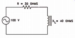
Figure 17. To find the current in this circuit you must first find the
impedance.
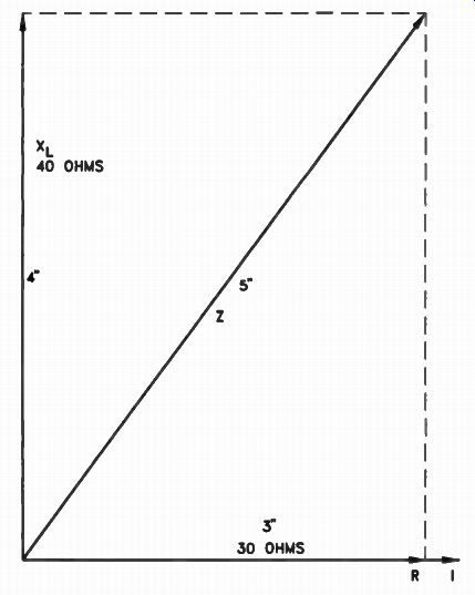
Figure 18. Vector solution for the impedance of the circuit.
We therefore draw a current vector with the resistance vector on top of it. If we assume a scale of 10 ohms to an inch, we draw the resistance vector 3" long, as shown in Fig.18. Since the voltage across the coil will lead the current by 90°, we draw the vector representing the inductive reactance 4" long for 40 ohms and rotate it 90° from the resistance vector. To complete the vector diagram, draw a dotted line from the end of the reactance vector parallel to the resistance vector, and another dotted line from the end of the resistance vector parallel to the reactance vector. We could then draw a line from the zero point up to the junction of these two dotted lines, which will give us the impedance vector. If you draw your vector to scale carefully and measure the impedance vector, you will find it is 5" long.
Therefore the impedance must be 5 x 10, or 50 ohms.
In the circuit shown in Fig.17, the current flow is 2 A, the voltage across the resistor is 2 x 30, or 60 V, and the voltage across the coil is 2 x 40, or 80 volts. Again, remember that you can't add these two voltages directly to get the generator voltage since the voltages are not in phase. Using the formula: EG - V ER2 + EL 2 Substituting 60 V for E R and 80 V for EL, you get: EG •• V602 + 802
= V3600 + 6400
- V10,000 = 100 V
At first glance, the voltages across the resistor and inductor in the circuit shown in Fig.17 add up to more than 100 V if you use simple arithmetic. This appears to contradict Kirchhoff's law. However, when you add the voltages vectorially, or by means of the formula we've given, you see that the sum of the two voltages is indeed equal to the source voltage. We can't add them directly using simple arithmetic because they are not in phase.
In the next lesson, when you study capacitors, you will find that a capacitive circuit has essentially the opposite effect of an inductive circuit.
In a capacitive circuit the current leads the voltage by 90 degrees.
The Q of a Coil
Since coils are wound with wire they have resistance as well as inductive reactance. The higher the ratio of inductive reactance to resistance, the better the coil. We call this relation ship the Q of the coil; we will study this in depth in future lessons. It is calculated with the formula:
Review
You should now understand the term phase and what it means when the current lags the voltage.
You should also understand that impedance is equal to the vector sum of the resistance and reactance. The impedance of a coil will always be greater than the resistance or reactance alone.
Sometimes impedance is only slightly higher than the inductive reactance, however.
The voltage across a component in an AC circuit can be found by using Ohm's law. The sum of the individual voltage drops in an AC circuit is equal to the source voltage, provided we add these voltages vectorially. We cannot add them by means of simple arithmetic and expect their sum to be equal to the source voltage.
Self-Test Questions
27 What do we mean when we say that the voltage and current in a circuit are in phase?
28 What is the phase relationship between the voltage and current across a resistor?
29 What is the phase relationship between the voltage and current across a coil?
30 What is meant by impedance?
31 A resistor and a coil are connected in series across a generator. If the voltage across the resistor is 12 V and the voltage across the coil is 16 V, what is the generator voltage?
ANSWERS TO SELF-TEST QUESTIONS
1. An air-core coil is wound on a cardboard form. The form merely supports the turns of the coil; it has no appreciable effect on the operation of the coil.
2. An iron core provides a better path for the magnetic lines of force. We say it has a lower reluctance.
3. Magnetomotive force is the force that sends magnetic flux around a magnetic circuit.
4. The ampere-turn is used to measure magnetomotive force.
5. A 2 A current flow through a 25-turn coil produces 50 ampere-turns.
6. Reluctance is the opposition to flux in a magnetic circuit. It is equivalent to resistance in an electrical circuit.
7. Yes; the reluctance in the magnetic circuit of an iron-core coil is much lower than the reluctance in the magnetic circuit of an air-core coil.
8. The permeability of a material indicates the ability of the material to pass the magnetic lines of force. The higher the permeability of the material, the less reluctance it will offer to magnetic lines of force.
9. In a magnetic circuit the flux is equal to the magnetomotive force divided by the reluctance.
10. A flux linkage is a magnetic line of flux cut ting through a single turn of a coil. If the magnetic line of flux cuts through two turns there will be two flux linkages, and if it cuts through five turns there will be five flux linkages.
11. There will be 12 flux linkages. A magnetic line of flux cutting through a single coil produces one flux linkage. Therefore, three lines cutting through four turns produces 12 flux linkages.
12. The voltage will be zero. If the number of flux linkages cutting a coil does not change, there is no voltage induced in the coil.
13. The induced voltage will produce a current which will, in itself, produce a magnetic field that opposes any change in flux linkages.
14. It will aid the original lines of force. If the field is reduced, the induced voltage produced in the coil will cause a current to flow in such a direction that the magnetic field produced will tend to prevent the number of flux linkages from decreasing. In order to do this, it must aid the original field.
15. Cutting lines of force, changing the reluctance, and changing the coil current are methods of changing flux linkages.
16. Inductance determines the voltage that will be induced in a coil.
17. It will oppose the applied voltage. The self induced voltage will try to keep the current constant so that the flux will remain constant.
To do this, it must oppose the applied voltage.
18. The henry is the unit of inductance.
19. The number of turns on the coil, the diameter of the coil, and the permeability of the core material affect the inductance.
20. The inductive reactance of a coil is the op position the coil offers to the flow of AC current through it.
21. The inductive reactance of a coil is measured in ohms.
22. 3768 ohms. To find the inductive reactance of a coil you use the formula: XL= 6.28 xfxL Substituting 60 for f and 10 for L we have: XL = 6.28 x 60 x 10 = 3768
23. 14 henrys. When two coils that are not mutually coupled together are connected in series, the total inductance is simply the sum of the two inductances.
24. 11 henrys. To find the total inductance of the two coils, use the formula: LT = L1 + L2 + 2M Substituting 4 H for L1, 3 H for L2, and 2 H for M we get: LT = 4 + 3 + (2 x 2) = 11 H
25. 9 henrys. To find the inductance of the two coils, we use the formula: L T = L1 + L2 - 2M Substituting 8 H for L1, 7 H for L2, and 3 H for M we get: L T = 8 + 7 - (2 x 3) = 9 H
26. 2200 millihenrys.
To convert henrys to millihenrys you must multiply by 1000 (which is the same as moving the decimal point three places to the right). 2.2 x 1000 = 2200
27. When we say that the voltage and current are in phase, we mean that any change in voltage produces a corresponding change in current. In other words, an increase in voltage causes an instant increase in current, or a decrease in voltage causes an instant decrease in current.
28. The voltage and current across a resistor are in phase.
29. The voltage across a coil will lead the current by 90 degrees. Another way of expressing the same thing is to say that the current lags the voltage by 90 degrees.
30. Impedance is the total opposition to current flow. It is made up of the reactive opposition and the resistive opposition to current flow.
31. EG = V ER 2 + EL i
= V 12z + 16z
= %/144 + 256
- Nrfor)
= 20 V
Lesson Summary
Some of the important facts you should remember from this lesson are:
• Voltage and current are induced in a coil and any attached conductors by the relative motion between the coil and the magnet.
• The amount of voltage produced by induction is directly proportional to the number of magnetic lines of force that are cut per unit of time.
• Since inductance acts to oppose a change in the direction of current flow, inductive reactance occurs when alternating current is applied to an inductive circuit.
• Circuit impedance can be calculated by taking the square root of the sum of the squares of the circuit resistance and the inductive reactance.
• Inductive circuits cause a phase shift in circuit voltage, such that voltage phase will lead the current by as much as 90°, depending on how much resistance is also in the circuit.
LESSON QUESTIONS
This is Lesson Number 2222.
Make sure you print your name, student number, and lesson number in the space provided on the Les son Answer Form. Be sure to fill in the circles beneath your student number and lesson number.
Reminder: A properly completed Lesson Answer Form allows us to evaluate your answers and speed the results and additional study material to you as soon as possible. Do not hold your Lesson Answer Forms to send several at one time. You may run out of study material if you do not send your answers for evaluation promptly.
1. If the reluctance of a magnetic circuit is increased, the flux will:
a. Increase.
CID Decrease.
c. Remain the same.
d. Disappear.
2. In a magnetic circuit, the equivalent of voltage is:
a. Reluctance.
Magnetomotive force.
c. Magnetic flux.
d. Permeability.
3. At a frequency of 100 Hz, the inductive reactance of 1 H is:
a. 6.28 ohms.
b. 62.8 ohms.
628 ohms.
d. 6280 ohms.
4. Two 15 H coils have a mutual inductance of 5 henrys. What is the total inductance when they are connected in series if the flux of one cell aids the flux of the other?
a. 20 henrys.
b. 30 henrys.
c. 35 henrys.
d 40 henrys.
5. If the two coils in the preceding question are connected so that the flux of one opposes the flux of the other, the total inductance is:
a. 20 henrys.
b. 30 henrys.
c. 35 henrys.
d. 40 henrys.
6. The impedance of the circuit shown below is:
a. 30 ohms.
b. 40 ohms.
c. 50 ohms.
d. 70 ohms.
7. If the impedance of the circuit shown below is 20 ohms, the current flow is:
a. 0.5 ampere.
b 1 ampere.
c. 2 amperes.
d. 4 amperes.
8. In the circuit shown below, the voltage across the coil is:
a. 2 volts.
b. 4 volts.
8 volts.
d. 16 volts.
9. If, in the circuit shown above, the frequency of the AC current is doubled, the voltage:
a. Across the resistor will increase.
b. Across the coil will remain the same.
c. Across the coil will decrease.
d. Across the coil will increase.
10. If the current flow in the circuit shown below is 1A, the generator voltage must be:
a. 300 volts.
b. 400 volts.
500 volts.
d. 600 volts.
--------------
NRI Schools
LEARNING NEVER ENDS
More and more it becomes evident that learning is a continuous process - that it is impossible to break the habit of studying with out slipping backward. Look around you at all the marvelous developments of the last 20 years. You have the advantage of having "grown up" with them, yet there are probably many things you wish you knew more about. Imagine what can happen in the years ahead if you do not keep abreast of the stream of new things that are bound to come.
Your NRI course is preparing you for the problems of today and tomorrow, but you cannot stop here. In 10 years, will you still be up to date? Yes, if you plan your future. Resolve now that you will keep up. You have the fundamentals; keep them fresh in your mind by constantly reviewing. Read and study technical literature and textbooks, join in discussion groups and listen to lectures, take advantage of every possible educational opportunity Then, and only then, can you face the future unafraid, no matter what technical developments the future may hold.
---------------------------