AMAZON multi-meters discounts AMAZON oscilloscope discounts
Table of Contents:
- Introduction
- How Capacitors Store Electricity
- Charging a Capacitor
- Capacitance
- Factors Affecting Capacitance
- Review
- Self-Test Questions
- Typical Capacitors
- Variable Capacitors
- Paper Capacitors
- Ceramic Capacitors
- Mica Capacitors
- Electrolytic Capacitors
- Review
- Self-Test Questions
- Capacitors in AC Circuits
- How AC Flows in AC Circuits with Capacitors
- Capacitive Reactance
- Capacitors in Series and Parallel
- Time Constant
- Voltage-Current Phase
- Voltage Distribution
- Impedance
- Review
- Self-Test Questions
- Answers to Self-Test Questions
- Lesson Questions
--------
Lesson Objectives
In this lesson you:
• Learn the principles of capacitance.
• Study how capacitors store electricity.
• Learn about the several different types of capacitors.
• See how capacitors affect electrical circuits, and how circuits affect capacitance.
• Study the difference in capacitive effects for alternating and direct current circuits.
INTRODUCTION
Electrical circuits contain opposing forces. You have studied inductance; now we turn your attention to a circuit element that has effects opposite to those of inductance. This element is capacitance. We can show that inductance and capacitance are opposites by matching each unit of inductance in a circuit with an equivalent unit of capacitance. The result is a circuit in which, at some frequency the capacitive effect balances the inductive effect, leaving a purely resistive circuit.
Some electronics engineers and manufacturers have devoted a lifetime to the development, improvement, and manufacture of capacitors. Great progress has been made in the quality, efficiency, reliability, and the size reduction of capacitors. Now, with microelectronics, capacitance becomes an integral, invisible part of these microscopically sized circuits.
Capacitance, like inductance, is a part of electronics. The study of capacitance is necessary for successfully solving the circuit problems which we constantly face in electronics.
-------------
HOW CAPACITORS STORE ELECTRICITY
A capacitor is nothing more than two pieces of metal separated by a nonconducting material.
The material may be air, a gas, a liquid, or a solid.
It is called the dielectric, and the metal elements are called plates. If there is nothing between the plates but air, we say the capacitor has an air dielectric.
A simple capacitor made of two metal plates with an air dielectric is shown in Fig.1. When the plates of the capacitor are connected to a battery, electrons will flow from the negative terminal of the battery into plate A. At the same time, electrons will flow from plate B to the positive terminal of the battery. This is because they are repelled by the surplus of electrons on plate A and attracted by the positive terminal of the battery.
At first, the voltage between the two plates will be zero. A very high current will flow, as shown in Fig.2, to charge the capacitor. As the capacitor charges, the voltage between the plates builds up, and while the current decreases, the capacitor voltage increases. Eventually, the potential between the plates is equal to the battery voltage. At this time, the current is zero, the voltage between the plates is equal to the battery voltage, and we say that the capacitor is charged.
If we disconnect the capacitor from the battery, the condition of imbalance that has been set up on the capacitor plates will remain. We have a surplus of electrons on one plate and a shortage of electrons on the other. Thus, we have electricity stored in the capacitor.
If we connect a wire from one plate of the charged capacitor to the other, electrons will flow from the side having a surplus of electrons over to the side having a shortage of electrons. The flow of electrons will continue until the number of electrons on the two plates is balanced, and there is no longer a charge on them. When the charge has disappeared, we say the capacitor is discharged.
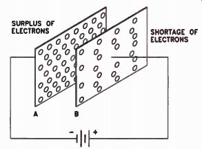
Figure 1. A capacitor is connected to a battery.
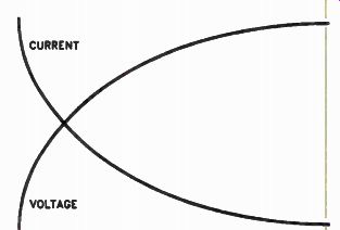
Figure 2. The relationship between the capacitor's voltage and current.
This is a very brief explanation of how a capacitor can store electricity. Large capacitors, particularly those used in high-voltage circuits, can store large amounts of electricity. Before touching the leads of a large capacitor, you should short the leads together with a screwdriver or similar object to be sure that the capacitor is discharged. If you touch the terminals of a charged capacitor you can receive an unpleasant and possibly dangerous shock.
You might wonder how we can use a capacitor in electronic equipment, because there is no complete path for current to flow through it. Indeed, as shown by the current curve in Fig.2, once the capacitor is charged so that the potential between the two plates is equal to the battery potential, there will be no further current flow.
Once a capacitor is charged, it effectively blocks the flow of de in the circuit.
Charging a Capacitor
A capacitor does not charge instantly. The length of time it takes to charge a capacitor depends upon two things: the size of the capacitor and the amount of resistance in the circuit.
You might think that there is no resistance in the circuit shown in Fig.1, but this is not true.
There is resistance in the leads used to connect the capacitor to the battery; in addition, there is the internal resistance of the battery itself, which is a function of how much current the battery can produce. These two resistances limit the rate at which the capacitor can charge. Because it takes time to charge a capacitor, there is a current flow in the circuit, as shown in Fig.2, when the capacitor is first connected to the battery. This current flows as long as the battery is charging the capacitor. When we disconnect the capacitor from the battery and discharge it, there will be a current flow once again, but this time in the opposite direction. Again, the length of time it takes the capacitor to discharge will depend upon the capacitance of the capacitor and the resistance in the circuit.
The charge on a capacitor depends upon the battery voltage used to charge it. A higher voltage exerts more force on the atoms of the plates and moves more electrons than a lower voltage.
There are other things, however, that affect the charge we can store in a capacitor. The electrical size of the capacitor is called the capacitance of the capacitor, and it is just as important as the charging voltage. Let's see what we mean by "capacitance".
Capacitance
The term capacitance is used to describe the electrical size of the capacitor in the same way that inductance is used to describe the characteristics of a coil, or the way that resistance is used to indicate the size of a resistor.
The unit of capacitance is the farad (pronounced FAIR-AD). The capacitance of a capacitor is a measure of its ability to store electricity. A capacitor with a high capacitance can store more electrons than a capacitor with a lower capacitance.
A farad actually represents an extremely large capacitance. It is so large that it is never used in electronics. The units used are the which is one millionth of a farad, and the picofarad, which is one millionth of a microfarad. The modern abbreviation for microfarad is µF, but you will also see mf and mfd used in older texts and diagrams. The abbreviation for picofarad is pF. In older literature, you might run into the term micro-microfarad, abbreviated mmf, which is also a millionth of a microfarad.
Sometimes you will want to change from uF to pF or from pF to uF. To change from the larger unit, microfarads, to the smaller unit, picofarads, move the decimal point six places to the right. In other words, a capacitor that has a capacitance of 0.0005 µF has a capacitance of 500 pF. You simply add the zeros to the right of the five and move the decimal point six places to the rig To convert from picofarads to microfarads, divide by 1,000,000. This is done by moving the decimal six places to the left. A 500 pF capacitor has a capacitance of 0.0005 µF. We simply add zeros to the left of the five and then move the decimal six places to the left.
The words microfarad and capacitor are both rather long, so technicians have shortened them.
They generally refer to a 2 uF capacitor as a two-mike cap. A 0.005 µF capacitor is called a double-oh five-mike cap, or a point double-oh five capacitor.
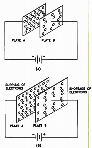
Figure 3. (A) The smaller capacitor. (B) The larger capacitor can store
a greater charge.
Factors Affecting Capacitance
The three factors that affect the capacitance of a capacitor are the area of the plates, the spacing between the plates, and the dielectric used between the plates.
In Fig.3, two capacitors are shown. In Fig.3(B), the capacitor has larger plates than the one in Fig.3(A), so we can force more electrons onto plate A and pull more electrons off plate B. Thus the capacitor in Fig.3(B) has a greater capacitance than the capacitor in Fig.3(A). We can also increase the capacitance by ad ding more plates. In Fig. 4(A), two plates -- A1 and A2 -- are connected. This effectively increases the plate area and hence the capacitance. Adding additional plates, as shown in Fig.4(B), increases the capacitance still more.
Reducing the spacing between the plates increases the capacitance. Figure 5(A), on page 6, shows a capacitor charged to the battery potential. If we move the plates closer together, as shown in Fig.5(B), the electrons on the negative plate force additional electrons out of the positive plate, thus increasing the positive charge on it. This in turn draws additional electrons into the negative plate, increasing the capacitance of the capacitor.
The third factor that affects the capacitance is the dielectric. The dielectric is the material between the plates of the capacitor. If, instead of air between the plates, we insert a piece of mica, paper, ceramic, or mylar, the capacitance increases, depending upon the dielectric constant of the material.
Dielectric Constant. The degree of effect of the dielectric material on the capacitance compared to the capacitance using air as the dielectric, is called the dielectric constant. The dielectric constant of mica is between six and eight because this is how much it increases the capacitance of a capacitor when inserted between the plates in place of air.
Different materials have different dielectric constants. Paper has about the lowest of any material you find used in capacitors, between 1.5 and 3. Ceramic has one of the highest dielectric constants of any material. The dielectric constant depends on the type of ceramic, but can be as high as 1500. Many ceramic capacitors have a relatively small physical size but a high capacitance.
Figure 6(A), on the next page, shows the plates of a capacitor before they are charged. Between the plates is an atom with electrons going around the nucleus in a circular path. Figure 6(B) shows the path of the electrons around the nucleus when the capacitor is charged. The electrons are repelled by the negative plate and attracted by the positive plate so that they travel in an oval path. This brings the electrons much closer to the positive plate so that they force additional electrons out of the positive plate. This increased shortage of electrons on the positive plate in turn attracts additional electrons onto the negative plate.
Air is a mixture of gases, and in a gas the atoms are relatively far apart. In solid materials, the atoms are closer together, so inserting a solid material dielectric increases the effect of this distortion. The amount by which the effect is increased depends upon the density of the material and the characteristics of the material itself. The effect is similar to pushing the plates of the capacitor closer together so that they al most touch. This enables us to get a very high capacitance.
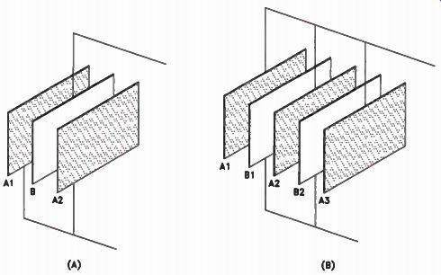
Figure 4. Adding plates to a capacitor increases the capacitance.

Figure 5. Because the plates are farther apart, the capacitor in (A)
has a smaller capacitance than the one shown at (B).
Voltage Rating. When manufacturers design a capacitor, they design it for use in a circuit with a certain maximum operating voltage. The voltage is usually marked on the capacitor and is called the working voltage. For example, a capacitor with a working voltage of 12 V is designed for use in a circuit where the de operating voltage is 12 V or less.
If you have to replace a defective capacitor, you should use a replacement with a working voltage at least as high as the working voltage of the original. You can use a capacitor with a higher working voltage if there is room. Usually, capacitors that have a higher working voltage are also larger.
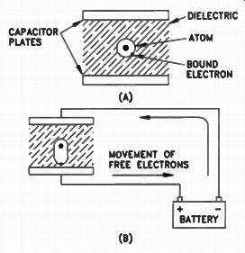
Figure 6. Shifting paths of the electrons in the dielectric.
Review
The basic action of a capacitor depends upon its ability to store an electric charge. There is no complete circuit through a capacitor, but current flows in a circuit in which the capacitor is connected while the capacitor is being charged and while it is being discharged. A capacitor is not charged instantly; the time it takes to charge a capacitor fully depends on the capacitance and the resistance in the circuit.
The electrical size of a capacitor is measured in farads, but the farad is such a large unit that the practical units are the microfarad (which is a millionth of farad) and the picofarad (which is a millionth of a microfarad). The capacitance of a capacitor depends upon the area of the plates, the spacing between the plates, and the dielectric between the plates. The dielectric constant of a material is a number that tells you the number of times the capacitance of a capacitor increases when this material is placed between the plates of the capacitor as compared to air.
The voltage rating of the capacitor tells you the maximum safe voltage that you can apply to a capacitor. Capacitors with a higher voltage rating can always be used to replace a defective capacitor in a piece of electronic equipment if there is space.
Self-Test Questions
1 What do we mean when we say that a capacitor is charged?
2 What two factors affect the length of time it takes to charge a capacitor?
3 What factor determines the amount of charge a capacitor can hold for a given amount of voltage?
4. What two practical units are used in electronics to indicate the capacitance of a cap
5.
6. Convert 680 pF to microfarads.
7. Name the two factors that affect the capacitance of a capacitor.
8. What is the die-electric constant of a material.
9. Why does a material with a dielectric constant greater than air have the effect of increasing the capacitance of a capacitor?
10. If a capacitor is marked 0.02 µF, 16 V, what does the marking 16 V mean?
--------------
TYPICAL CAPACITORS
Capacitors are also divided into fixed and vari able types. A fixed capacitor has a fixed capacitance that cannot be changed, whereas a variable capacitor, as the name implies, is designed so that its capacitance can be varied by some convenient method. Most variable capacitors use an air dielectric, and are called air capacitors. Some variable capacitors have a mica dielectric and are referred to as variable mica capacitors. Most fixed capacitors use some dielectric other than air.
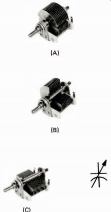
Figure 7. (A) The capacitor is adjusted for minimum capacitance, (B)
half capacitance, and (C) maximum capacitance. The capacitor's schematic
symbol is also shown.
Variable Capacitors
Three views of a typical variable capacitor are shown in Fig.7 The capacitor is made up of two sets of plates as shown in Fig.7(A). The bottom set of plates is connected to two shafts held in place by two insulators. Connected to these shafts are two terminals for external connections. One shaft and one of the terminals are visible in the photograph.
The bottom plates, called the stator, are stationary. The top plates con a rotatable shaft, causing the top set of plates to move in between the stator plates.C1 that can rotate are called the rotor plates or siiiipTy the n Fig.7(B), the rotor is turned 90° so that the rotor plates are half-meshed with the stator plates. In Fig.7(C), the rotor has been rotated an additional 90° so that the plates are completely meshed with the stator plates. The schematic symbol is also shown.
Figure 8 shows what happens as we turn the rotor inside the stator. Remember, we said that one factor that affects the capacitance of a capacitor is the area of the plates. In the illustration shown in Fig.8(A), the area of the rotor that is opposite the stator is extremely small. The only area affected is the edges of the two plates.
There is a small capacitance between the edge of the stator and the edge of the rotor. As the capacitor turns to the position shown in Fig.8(B), about one quarter of the rotor plate is opposite the stator plate. The capacitance is much greater than at Fig.8(A). In Fig.8(C) about half the rotor is opposite the stator, in Fig. 8(D) about three fourths, and at Fig. 8(E) the entire rotor is meshed inside the stator so that there is maximum capacitance.
In the capacitor shown in Fig.8, there is just one rotor plate and one stator plate. In the capacitor shown in Fig.7, notice that there are a number of plates on both the rotor and on he stator. By using a number of stator and rotor plates, we can get a much higher capacitance capacitor because the area of the plates is increased.
The capacitance of a variable capacitor also depends on the spacing between the plates. Look he two capacitors shown in Fig.9. The capacitor in Fig.9(A) is much larger than the one at Fig.9(B), but they have the same maximum capacitance because the spacing between the plates in the capacitor shown in Fig.9(A) is double the spacing between the plates in the capacitor shown at Fig.9(B). The capacitor shown at Fig.9(A) is built for use in circuits in which voltages are higher than those in circuits that use the capacitor shown in Fig.9(B). Another type of variable capacitor is the trimmer capacitor. A typical trimmer capacitor is shown in Fig.10. These capacitors are used to trim, or adjust, tfie - cii;Eiiit to compensate for variations in other components in the circuit.
A trimmer capacitor is made by securing a fixed plate to an insulated material. On top of the fixed plate is a piece of mica, and the movable plate is secured by a rivet so that it does not touch the fixed plate. The spacing between the plates is changed by tightening or loosening the adjusting screw. If additional capacitance is needed, it can be obtained simply by adding another layer of mica over the adjustable plate and then adding a second fixed plate. Another layer of mica is then added along with a second adjustable plate. Additional layers of plates and mica can be added so that the trimmer may have a number of stationary and adjustable plates.
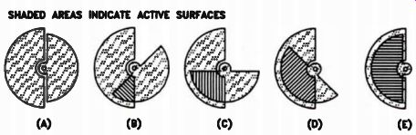
Figure 8. How a variable capacitor with straightline capacitance plates
works.
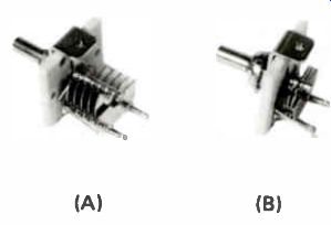
Figure 9. (A) This capacitor has the same maximum capacitance as the
one shown at (B).
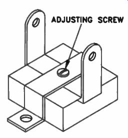
Figure 10. A typical trimmer capacitor.
Paper Capacitors
A paper capacitor is made from two sheets of tinfoil, with a sheet of paper between them, as shown in Fig.11 (A). The tinfoil and paper are rolled, as shown in Fig.11(B), until they are shaped like Fig.11 (C). Wire leads are then attached to the foil sheets that protrude from each end of the capacitor. After the leads have been attached to the tinfoil, the capacitor is encased in a molded container that keeps out moisture and dirt.
The paper capacitor is so named because a paper dielectric is used between the two plates.
Today, however, paper alone is seldom used as the dielectric. Mylar and mylar-coated paper are more widely used. Polyester materials are also used; a capacitor with a polyester dielectric has a very high resistance to humidity. Polystyrene is also used as a dielectric; polystyrene capacitors have a very high insulation resistance.
Two typical capacitors of this type are shown in Fig.12 along with the schematic symbol. The lower capacitor has axial leads, meaning that the leads come out of the ends parallel to the body of the capacitor. The upper capacitor has radial leads that come out of the capacitor at an angle of 90° to the capacitor body.
Years ago, capacitors caused a lot of problems in electronic equipment. However, with today's manufacturing techniques you seldom find a defective capacitor. If anything happens to the case so that it is not a perfect seal, moisture can seep into the capacitor and cause leakage. Some times in a radial capacitor, the case is damaged at the end where one of the leads is attached. The connection to the lead may break off, in which case the capacitor is open, or the insulating foil may be damaged, and the capacitor shorted. If you suspect a capacitor is defective, try a new one in the circuit.
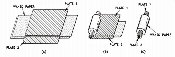
Figure 11. How a paper capacitor Is made.
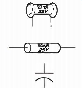
Figure 12. A typical paper capacitor and its schematic symbol.
Ceramic Capacitors
You find more ceramic capacitors in modern electronic equipment than any other type. They are widely used because they are reliable, economical to manufacture, and because they have a relatively large capacitance for their small size.
There are three types of ceramic capacitors: the disc, the tubular, and the feed-through. All three types are shown in Fig.13 along with the schematic symbol for a feed-through capacitor.
The symbol used for tubular and disc ceramics is the same symbol that is used for a paper capacitor.
Of the three types of ceramic capacitors, the disc is by far the most widely used. You seldom see tubular ceramic capacitors because they are much more expensive to manufacture than discs.
Feed-through capacitors are used as bypass capacitors in high-frequency circuits.
Disc capacitors are made with capacitances from less than 1pF up to several uF. Disc capacitors are like resistors in that they have different tolerances. Common tolerances are 5, 10, or 20 percent. Often the tolerance is indicated on the capacitor by a letter rather than the actu tolerance figure. The letter J is used to represent a 5% tolerance, K a 10% tolerance, and M a 20% tolerance. You'll also find disc capacitors with a tolerance rating of +100% or -O. The letter P is used to represent this tolerance. Another tolerance rating is +80% to -20%, where the letter Z is used to represent this tolerance. Still another tolerance is GMV, or guaranteed mini mum value. That is, a capacitor marked 100 pF GMV has a capacitance at least that high. It could have a capacitance of 200 pF or 500 pF, or even higher. The manufacturer has simply guaranteed the minimum capacitance to be at least the value stamped on it.
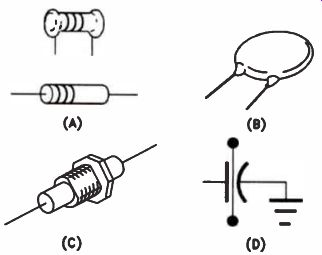
Figure 13. (A) Tubular, (B) disc, and (C) feed-through ceramic capacitors.
(D) The schematic symbol for a feed through capacitor.
Ceramic capacitors also have temperature coefficients. This means that the capacitance may change as the temperature changes. For example, a common type of ceramic capacitor is called a Z5U. This capacitor is designed for operation between 10°C and 85°C. The label Z5 gives you this information. The letter U tells you that the capacitance may change as much as +22% or -56% over that temperature range.
However, in many applications, this change in capacitance is not important. The Z5U capacitor is frequently used because it is generally the most inexpensive capacitor available.
Ceramic capacitors are also made with a lower temperature coefficient. For example, a capacitor labeled Z5F has a temperature coefficient of only 7.5 percent. Z5P indicates a temperature change of 10% within the operating range.
These capacitors are only used in circuits where a change of capacitance can cause a problem Because they are more expensive than the Z5U type.
You will also see ceramic capacitors marked either with the letter N or P followed by a number. The N indicates negative temperature coefficient and P indicates positive temperature coefficient. The capacitance of a capacitor with a negative temperature coefficient always decreases as the temperature increases. The capacitance of a capacitor with a positive temperature coefficient increases as the temperature increases. The larger the number following the letter N or E the greater the capacitance change for a given temperature change.
Some ceramic capacitors are marked NPO, which stands for negative, positive, zero. These have neither a negative nor a positive tempera ture coefficient. Its value does not change as the temperature changes. These capacitors are found only in critical circuits where any change in capacitance would upset the performance of the circuit.
The closer the tolerance of a capacitor and the smaller the temperature coefficient, the more expensive the capacitor is. If you have to replace a defective ceramic capacitor, you can always use one with the same tolerance and the same temperature coefficient as the original. In man cases, you can use a Z5P capacitor to replace a Z5U, or you can use a Z5F capacitor to replace a Z5P capacitor. However, if you have to replace a capacitor with a negative temperature coefficient one with a positive temperature coefficient, or an NPO capacitor, you should use a replacement with the same temperature coefficient.
Ceramic capacitors are manufactured with many different voltage ratings. Usually, the higher the voltage rating, the larger the physical size of the capacitor. The operating voltage in 7' modern electronic equipment using transistors and integrated circuits is generally quite low, so most ceramic capacitors have a voltage rating as low as 50 volts. When a capacitor of a higher voltage rating is required, the manufacturer specifies a higher voltage rating.
Ceramic capacitors are very reliable, but occasionally a lead wire breaks and a short develops across the capacitor. When this hap , pens, the shorted capacitor is not hard to find because it has a low resistance reading. Unless there is something connected directly across the capacitor, a low resistance reading indicates that the capacitor is shorted.
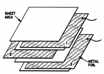
Figure 14. How a mica capacitor is made.
Mica Capacitors
Figure 14 shows the construction of one type of mica capacitor. It is made by placing thin metal foil sheets between thin sheets of mica.
The entire unit is sealed in a Bakelite or ceramic container. Mica is brittle and can't be rolled into a round form like paper or mylar, so the shape of a mica capacitor is flat.
Another type of mica is the silver mica capacitor. In this capacitor, thin layers of silver are sprayed onto the mica sheets, as shown in Fig.15. Since the silver layers are very thin, opposite plates of the capacitor can be brought very close together to obtain a relatively high capacitance in a small package.
Although mica capacitors are excellent capacitors, they are no longer frequently used because they are much more expensive than other types.
Figure 15. A silver mica capacitor.
Electrolytic Capacitors
Electrolytic capacitors are widely used in electronic equipment because you can get a / higher capacitance for a given physical size than in any other type of capacitor. There are two types of electrolytic capacitors: aluminum' capacitors, which use aluminum for the plates, and tantalum capacitors, which use tantalum for the plates. Of the two, the aluminum capacitor is more widely used because aluminum is much less expensive than tantalum.
An electrolytic capacitor is made up of two long strips of metal with an electrolyte in paste form placed between the two plates, as shown in Fig.16(A). The anode plate is treated before the capacitor is assembled to produce a coating of oxide on the surface of the plate. The oxide, which is very thin, acts as the dielectric. A gauze type material soaked with the electrolyte is then laid in contact with the oxide. The other plate is then placed on top of the gauze. The gauze, saturated with the electrolyte, and the top plate form the cathode or negative plate of the capacitor. The whole assembly is then rolled up with the negative plate on the outside, then encased in a metal container.
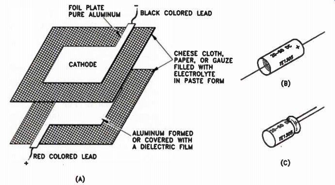
Figure 16. (A) Electrolytic capacitors are made of two plates with an
electrolytic paste form placed between the two plates.
The assembly is then rolled and placed in a tubular metal can. (El) The leads are then brought out of the two ends of the capacitor, or as shown at (C), the leads are brought out of one end of the capacitor.
In the double-ended electrolytic capacitor shown in Fig.16(B), the lead from the negative plate comes out one end of the capacitor and is in contact with the metal container. The lead from the positive plate, or anode, comes out the other end and this end is sealed with an insulating material. In the single-ended electrolytic capacitor shown in Fig.16(C), the two leads come out of the same end of the capacitor.
Electrolytic capacitors can be made with very high capacitances because the dielectric, which is an oxide coating on one of the plates, is very thin. Since the other plate consists of the aluminum and the gauze saturated with electrolyte, the two plates are very close together. You find some very small electrolytic capacitors with very high capacitances.
As we mentioned earlier, aluminum is more widely used in electrolytic capacitor because it is less expensive than tantalum. However, tantalum capacitors are better capacitors and are used in applications where the superior performance of the capacitor justifies the additional expense.
Polarity. Electrolytic capacitors can only be used in de or pulsating DC circuits. The plate called the anode must always be connected to the positive side of the voltage source, and the plate called the cathode must always be connected to the negative side of the voltage source. If you connect an electrolytic capacitor into the circuit backwards, or use it in an AC circuit, a very high current flows through the capacitor, destroying it.
In some electrolytic capacitors, the anode is marked with a + sign and the cathode with a - sign. In most electrolytic capacitors, however, only one of the two leads is marked. Once you've found the - sign indicating the cathode or the + sign indicating the anode, you can identify the unmarked lead.
Voltage Rating. The thinner the dielectric oxide coating in an electrolytic capacitor, the higher the capacitance; but the thinner the dielectric, the lower the voltage that can be applied to the capacitor. Manufacturers specify the maximum voltage that can be applied to an electrolytic capacitor. If you use an electrolytic capacitor in a circuit where the operating voltage is higher than the voltage rating of the capacitor, the capacitor will most likely break down.
Defects. Electrolytic capacitors are amongst most troublesome components in electronic equipment because they deteriorate, particularly if they are not used. You should not buy a large stock of electrolytic capacitors. Avoid keeping unused caps longer than six months. you do have a capacitor longer than six months--before using it, you should place a small operating voltage across the capacitor and gradually increase it until the voltage applied to the capacitor slightly exceeds the rated voltage f the capacitor. Electrolytic capacitors also deteriorate as they are used. The moisture in the electrolyte slowly escapes so that the capacitance of the capacitor decreases.
The dielectric in an electrolytic capacitor is not a perfect insulator. Some electrons can cross from the negative plate to the positive plate. In a good capacitor this leakage current is very low, but in time the leakage current may become excessive. When this happens, the capacitor be comes warm. Anytime you find a warm or hot electrolytic capacitor, you should replace it.
Review
In this section we have discussed a number of different types of capacitors. In general, you can classify them into two types: those in which the capacitance is variable and those in which the capacitance is fixed.
It is not important that you remember how the various types of capacitors are made. It is important to remember that capacitors can open, short, and develop intermittent defects. A low resistance reading across a capacitor indicates that the capacitor is shorted or has developed excessive leakage.
Self-Test Questions
11. What do we mean when we say that the dielectric of a variable capacitor is air?
12. Why are capacitors such as paper or mylar capacitors molded in a ceramic type of, material?
13. Why aren't mica capacitors more widely used in electronic equipment?
14. What does Z5F stamped on a ceramic disc capacitor indicate?
15. Name two metals used in electrolytic capacitors.
16. What do we mean when we say an electrolytic capacitor has polarity?
17. Can an electrolytic capacitor with a DC voltage rating of 10 V be used in a circuit where the operating voltage is 15 volts?
18. If you notice that an electrolytic capacitor is getting hot, what should you do?
-----------------
CAPACITORS IN AC CIRCUITS
Capacitors are rarely used in purely direct current circuits. Once a capacitor is placed in a DC circuit and charged, there is no further current flow in the circuit. Capacitors are most important when used in AC circuits and in circuits that have both AC and dc.
How AC Flows in AC Circuits with Capacitors
Figure 17 shows a simple circuit with a capacitor connected across an AC generator.
There is a current flow in this circuit, and the exact amount of current depends upon the voltage of the generator, its frequency, and the capacitance of the capacitor.
When terminal 1 of the generator is negative and terminal 2 is positive, electrons flow from terminal 1 into the side of the capacitor marked A. Electrons are forced out of the side marked B to terminal 2 of the generator, which attracts these electrons because it is positive. During the next half-cycle, the polarity of the generator reverses so that terminal 1 is positive and terminal 2 is negative. Now electrons on the side of the capacitor marked A are pulled out by terminal 1 which is positive, and electrons are forced into side B of the capacitor by terminal 2 of the generator, which is negative.
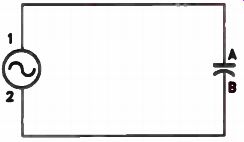
Figure 17. A capacitor connected across a generator.
Electrons flow back and forth in the circuit as the generator goes through first one half-cycle and then the other. They flow first into one side of the capacitor, forcing electrons out of the other side, then the opposite. Notice that electrons do not flow through the capacitor. The plates of the capacitor are separated by a dielectric and the dielectric is a nonconducting material. However, because the capacitor stores the charge in each direction of current flow, and discharges in the opposite direction when the polarity changes, we have the effect of the current flowing in the circuit.
Refer to Fig.18. At the start of the AC cycle when the voltage is zero, there are electrons in both plates of the capacitor. The electrons in each atom of the dielectric revolve around the nucleus, as shown in Fig.18(A). However, when electrons begin to move into one plate, as shown in Fig.18(B), and out of the other plate, the electrons in the dielectric are forced out of their normal path as shown. Thus, although an electron flowing into plate 1 does not reach plate 2, it does force another electron in the dielectric over near plate 2, and this in turn forces an electron out of plate 2.
If the AC voltage decreases and finally drops to zero, the electrons in the dielectric return to the normal position, as shown in Fig.18(C). During the next half-cycle, when the polarity of the generator reverses, an electron is forced into plate 2. This in turn forces an electron in the dielectric out of its normal position and toward plate 1. This action pushes an electron out of plate 1. Thus, we have the effect of current flowing through the capacitor in the opposite direction, although the electrons flowing into one plate never actually go through the dielectric into the other plate of the capacitor.
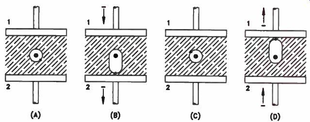
Figure 18. When AC is applied to a capacitor, the bound electrons in
the dielectric move first one way, then the other. As a result, the effect
is that of alternating current flowing through the capacitor.
You can see that there is a back and forth motion of electrons through the conductors connected to the capacitor. Because the electrons in the dielectric move back and forth, we can say that AC current flows through a capacitor, even though the electrons never get through the dielectric into the other plate. Because of this current continuity, capacitors can be used in AC circuits. They are also very useful in circuits where there is both AC and dc. The capacitor can be used to block the dc, while at the same time allowing the AC to flow through the capacitor.
In allowing electrons to flow back and forth, the capacitor's action serves as a good demonstration of what AC is. The actual movement of each electron is very small, but there may be a large number of electrons moving back and forth over a very short distance. The distance of the electron's travel is unimportant; the important thing is the number of electrons in motion. If we have a large number of electrons in motion, we have a large current.
Capacitive Reactance
The capacitor does not allow electrons to move back and forth without offering opposition.
Capacitors offer opposition to the flow of AC current through them. This opposition is called capacitive reactance. This opposition is measured in ohms, just as the inductive reactance of a coil is measured in ohms. However, there is a great deal of difference between inductive reactance and capacitive reactance.
Capacitive reactance is represented by the symbol Xc. It can be expressed by the formula: 1 Xc = 6.28 xfxC The 6.28 is the value of 2pi. Remember, this appeared in the formula for inductive reactance.
Notice that the formula is similar to the formula for inductive reactance except that it is inverted.
In other words, the expression is divided into 1.
In this formula, f is the frequency expressed in hertz and C is the capacitance in farads. We know that the farad is too large a unit for practical use in electronics, so we can write the formula in another way by expressing C in microfarads. To do this we divide 6.28 into 1 and multiply the result by 1,000,000. We get:
Xc = 159 000 /fc
In this expression f is the frequency in hertz, and C is the capacitance in microfarads.
There are several important things that you can learn from this formula. For example, let's find the reactance of a 1 µF capacitor at a frequency of 10 Hz.
xc 11::10$0 159,000 15,900ohms 10 x 1 - 10 –
If we increase the frequency to 100 cycles, we get: Xc = 159 000 100 xl - 1590 ohms when we increase the frequency from 10 Hz to 100 Hz (in other words increase the frequency 10 times), we reduce the capacitive reactance by a factor of 10. We say that the reactance varies - inversely as the frequency. This simply means that as the frequency increases, the reactance decreases. This is opposite to the effect that an increase in frequency has on inductive reactance.
The same thing happens if we increase the capacitance. At the frequency of 100 Hz, if we increase the capacitance from 1 µF to 10 µF, we get: 159,000 Xc - 100 x 10 - 159 ohms
Thus, an increase in capacitance has the same effect on the capacitive reactance as an increase in frequency. And increasing either the frequency or the capacitance reduces the capacitive reactance. Even a very small capacitor can have a low reactance if the frequency is high enough.
For example, a 1 pF capacitor has a reactance of 1590 ohms at a frequency of 100 MHz. This is within the FM broadcast band. At a frequency of 1000 MHz, which is only slightly higher than the frequency used by some UHF TV stations, the reactance is only 159 ohms.
Capacitors in Series and Parallel
When you connect two capacitors in series, you are connecting two capacitive reactances in series. It is like connecting two resistances in series. The total capacitive reactance is the sum of the two reactances. Since the reactance increases, the capacitance must decrease. As a matter of fact, if you connect two 10 µF capacitors in series, the total capacitance of the series combination is exactly half of 10 µF, or 5 µF. When two capacitors are connected in series, you can find the total capacitance by using the formula:
C1 x C2
CT - C1 + C2
If there are more than two capacitors, you can find the total capacitance of two at a time by using the same formula that we use to find the total resistance when more than two resistors are in parallel.
When capacitors are connected in series, the total capacitance is always less than the capacitance of the smallest capacitor. Remember that this is the same as resistors in parallel where the total resistance is always less than the resistance of the smallest resistor.
When you connect two capacitors in parallel, you are connecting two reactances in parallel. If you connect two 10 µF capacitors in parallel, you have half the capacitive reactance of either capacitor alone. Since the capacitive reactance goes down, the capacitance must increase. To find the total capacitance of capacitors connected in parallel, you simply add the capacitances.
Time Constant
When you connect a capacitor across a battery, it takes a certain amount of time for the capacitor to charge. The length of time depends on the capacitance of the capacitor and the resistance in the circuit. Even if you connect a capacitor directly across the battery, the battery has internal resistance, so some time is involved in charging the capacitor.
If we connect a capacitor in series with a resistor across a battery, as shown in Fig.19, the voltage across the capacitor builds up following a curve as shown in Fig.20. Notice that at first the capacitor charges quite rapidly and then, as it is charged, the rate at which the voltage builds up decreases. This is because when you first connect the capacitor across the battery, the capacitor voltage is zero and the full battery voltage is forcing electrons into the one plate and out of the other. As the capacitor begins to charge, the voltage forcing the current flow decreases because the voltage causing the current to flow is the battery voltage minus the capacitor voltage. Since the effective charging voltage decreases, the rate at which the charge builds up decreases.
The length of time it takes the capacitor to charge is known as the time constant of the R-C circuit. However, by definition, one time constant is. The length of time it takes the capacitor to charge to approximately 63% of the source voltage, not to the full source voltage his value is shown in Fig.20. The time constant in seconds of any R-C circuit can be found by multiplying the resistance of the resistor in megohms times the capacitance of the capacitor in microfarads A capacitor is considered, again by definition, to be fully charged (100%) after five time constant have elapsed.
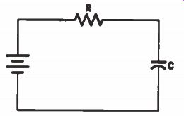
Figure 19. A resistor and a capacitor connected in series across a battery.

Figure 20. How a capacitor charges.
By this formula, a 2 uF capacitor in series with a 1-megohm resistor has a time constant 2 x 1= 2 seconds. This means that it takes two seconds for the capacitor to charge up to 63% of the source voltage. Ten volts applied to this combination will charge the capacitor to 6.3 V in two seconds.
If we apply 100 V, the capacitor voltage rises to 63 V in two seconds. Decreasing the size of either the resistor or the capacitor decreases the time constant. Increasing the size of either the resistor or the capacitor increases the time constant.
Voltage-Current Phase
In the preceding example, notice that when the capacitor and resistor combination is first connected across the battery, a very high current flows in the circuit. However, at this first instant when the combination is connected across the battery, there is no voltage across the capacitor.
The current is at a maximum and the voltage across the capacitor is at a minimum, or zero, voltage.
As the voltage across the capacitor builds up, the current flow in the circuit decreases until finally, when the capacitor is fully charged to a value equal to the battery voltage, the current drops to zero. At this point, the source voltage is unable to force any additional electrons onto the one plate of the capacitor or to pull electrons off the other plate.
Essentially, the same thing happens on a continuing basis when a capacitor is used in an AC circuit. When the AC voltage across the capacitor builds up, the current decreases until, by the time the capacitor is fully charged, the current has dropped to zero. When the voltage across the capacitor peaks and begins to reverse in polarity with the phase change in the applied AC voltage, the current must reverse to flow in the opposite direction.
During the second quarter of the AC cycle, the capacitor voltage drops from maximum to zero while the discharge current flowing in the circuit increases from zero to maximum. As the voltage across the capacitor builds up in the opposite direction, the current begins to decrease until, at the instant when the capacitor is fully charged with the opposite polarity, the current flow in the circuit has dropped to zero again.
The relationship between the current and voltage in a capacitive AC circuit is shown in Fig.21. Notice that in this circuit the current is leading the voltage by 90 degrees. In other words, it is always one-quarter cycle ahead of the voltage. Remember that this is the opposite of what happens in an inductive circuit where the current lags the voltage by 90 degrees.
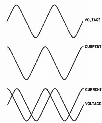
Figure 21. The phase relationship between current and voltage in a capacitive
circuit.
Voltage Distribution
When a resistor and a capacitor are connected in series across an AC generator, as shown in Fig.22, we cannot measure the resistor voltage, then the capacitor voltage, and add them directly together to get the generator voltage. This is because the voltage across the resistor is in phase with the current, but the voltage across the capacitor lags the current by 90 degrees. To add them, we must use a formula very similar to the one we used for inductive circuit voltages:
EG .. VEtt + E
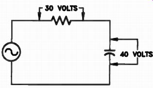
Figure 22. The voltage across the resistor.
Substituting the values shown in Fig.22 we get:
EG = V30z + 402
= V 900+1600
= V2500 = 50 V
We can also find the generator voltage by means of a vector addition of the two voltages, as shown in Fig.23. First, draw the current vector I. Since the resistor voltage is in phase with the current, draw the resistor voltage ER over top of the current vector. Using a scale of 1". 10 V, draw the resistor vector 3" long to indicate 30 volts. Now draw the capacitor voltage vector Ec lagging by 90° and 4" long to represent 40 V, as shown. Next, draw a dotted line parallel to the capacitor voltage vector from the end of the resistor vector and another dotted line from the end of the capacitor voltage vector parallel to the resistor voltage vector. Where the two intersect, draw a line representing the generator voltage at EG. If you measure this line, you'll find that it is 5" long, which indicates that the generator voltage is 50 volts.
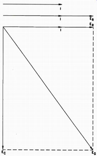
Figure 23. Vector addition of resistor and capacitor voltage in Fig.22.
Impedance
We can use the same type of formula to find the impedance in an R-C circuit that we used to find the impedance in an RL circuit.
Z . v it2 + e
If, in the circuit shown in Fig.22, the resistance is 300 ohms and the capacitive reactance is 400 ohms, we can substitute these values in the formula to find the impedance.
Z = V3002 + 4002 - V 90,000+160,000 = 1/250,000 = 500 ohms
We can also use a vector diagram to find the impedance, as shown in Fig.24. Using a scale of 100 ohms = 1", we draw a current vector first.
Then we draw the resistor vector R 3" long as shown. Next, we draw the capacitive reactance vector Xc 4" long and then complete our vector diagram. The impedance vector Z be equal to 5", which represents 500 ohms.
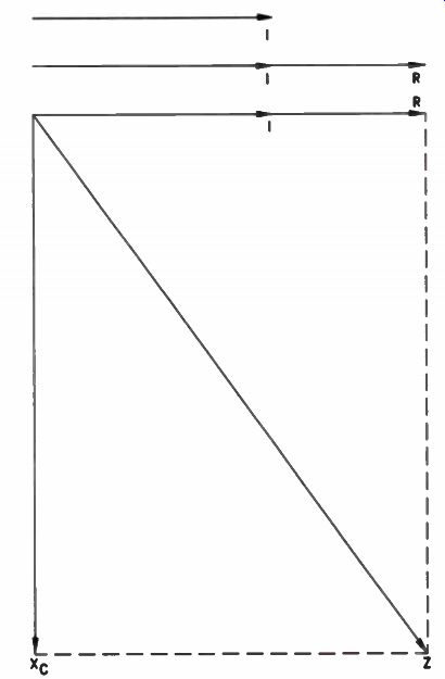
Figure 24. Vector addition of impedance.
Review
It is important for you to remember that in creasing either the frequency or the capacitance of a circuit reduces the capacitive reactance.
Though you seldom have to calculate the actual reactance of a capacitor, you should remember the formula in order to remember that increasing frequency or capacitance reduces reactance.
You should remember what we mean by the time constant of an R-C circuit. It is the time it takes a capacitor to charge to 63% of the applied voltage. Increasing the resistance or the capacitance of the circuit increases the time constant, whereas reducing the resistance or the capacitance reduces the time constant.
Remember that in a capacitive circuit the current leads the voltage by 90 degrees. We can also say that the voltage lags the current by 90'; both mean the same thing. Remember that in an R-C circuit, you cannot arithmetically add the voltage across a resistor and the voltage across a capacitor to get the source voltage. You must add them vectorially or by means of the formula. The same is true of impedance in an R-C circuit.
Self-Test Questions
19. When a capacitor is connected across an AC generator, does current flow from the generator?
20. When a capacitor is connected across a generator, does current flow through the capacitor?
21. What is the name given to the opposition that a capacitor offers to the flow of ac?
22. If either the frequency of the applied AC or the capacitance of a capacitor is increased, what happens to the capacitive reactance?
23. What do we mean by the time constant of an R-C circuit?
24. What is the time constant of a 0.02 pF capacitor charging through 2.2M resistor?
25. If the time constant of an R-C circuit is two seconds when it is charged across a 10 V battery, what is the time constant when it is connected across a 100 V battery?
26. If a generator is connected across a resistor and a capacitor in series, what is the generator voltage if the voltage across the resistor is 9 V and the voltage across the capacitor is 12 volts?
27. If a 6-ohm resistor is connected in series with a capacitor having a capacitive reactance of 8 ohms, what will the impedance of the combination be?
ANSWERS TO SELF-TEST QUESTIONS
1. When we say a capacitor is charged, we mean there is a surplus of electrons on one plate and a shortage of electrons on the other.
2. The length of time it takes to charge a capacitor is affected by the resistance in the circuit and the capacitance of the capacitor.
3. The capacitance of the capacitor.
4 The microfarad, which is a millionth of a farad, and a picofarad, which is a millionth of a microfarad.
5. 3300 pF
To convert microfarads to picofarads, you multiply by 1,000,000 or move the decimal point six places to the right.
6. 0.00068 uF. To convert picofarads to microfarads, you move the decimal point six places to the left.
7. The area of the plates, the spacing between the plates, and the dielectric of the medium between the plates.
8. The dielectric constant of a material tells you how many times the capacitance of the capacitor increased by substituting the material between the plates of a capacitor in place of air.
9. It has the effect of reducing the spacing between the plates of the capacitor.
10. This is the maximum DC voltage that can be applied across a capacitor.
11. We mean the plates are separated by air; there is no solid dielectric between the plates.
12. To seal the capacitor so moisture can't seep into the capacitor.
13. They are expensive.
14. Z5 indicates that the capacitor is designed for operation between 10°C and 85°C. The F indicates that the capacitance should not change more than ±7.5 within the capacitor's normal temperature range.
15. Aluminum and tantalum.
16 One plate must always be connected to a positive voltage and the other to a negative voltage.
17. No.
18 Replace it.
19. Yes. Current flows from the generator to charge the capacitor with one polarity during one half-cycle and then flows to the opposite direction to charge the capacitor with the opposite polarity during the next half-cycle.
20. No. While electrons do flow in the circuit, they do not flow through the capacitor.
21. Capacitive reactance.
22. It is reduced.
23. It is the length of time it takes the capacitor to charge up to approximately 63% of the applied voltage.
24. 0.044 second. The time constant equals 2.2 x 0.02 = 0.044 second.
25. Two seconds. The time constant is exactly the same because the charging voltage has no effect on the time constant.
26. 15 V. Use the formula: EG = VEtt + EÉ V91 + 121
= V81 + 144 =
= 15 V 27 10 ohms.
Use the formula: Z VR2 +
= V6e + 8 e
= V36 + 64 = V - 11710
= 10 ohms
-----------
Lesson Summary
Some of the important facts that you should remember about this lesson are:
• A capacitor is basically no more than two flat pieces of conductor, separated by an insulator.
• A capacitor charges at a rate determined by its capacitance and by the total resistance in the circuit.
• Capacitors are usually measured in microfarads, and have peak voltage ratings.
• Capacitors can be fixed or variable, and polarized or nonpolarized in nature.
• Current leads voltage in a capacitive circuit by as much as 90 degrees.
------------
LESSON QUESTIONS
This is Lesson Number 2223.
Make sure you print your name, student number, and lesson number in the space provided on the Lesson Answer Form. Be sure to fill in the circles beneath your student number. Code the lesson number as shown at the right.
Reminder: A properly completed Lesson Answer Form allows us to evaluate your answers and speed the results and additional study material to you as soon as possible. Do not hold your Lesson Answer Forms to send several at one time. You may run out of study material if you do not send your answers for evaluation promptly.
1. The capacitance of a capacitor can be increased by increasing:
a. The charging voltage.
b. The area of the plates.
c. The spacing between the plates.
d. The resistance in the circuit.
2. 0.0001 µF is equal to:
a. 1 pF
b. 10 pF 100 pF 1000 pF
3. In place of a 10 µF, 35 V capacitor, you can use:
a. 10 µF, 10 V capacitor.
b. 10 µF, 20 V capacitor.
c. 10 µF, 30 V capacitor.
d. 10 µF, 40 V capacitor.
4. 470 pF is equal to:
a. 0.000047 µF
b. 0.00047 uF
c. 0.0047 uF.
d. 0.047 µF
5. The capacitive reactance of a 25 µF capacitor at a frequency of 100 cycles is:
a. Approximately 6000 ohms.
b. Approximately 600 ohms.
c. Approximately 100 ohms.
d. Less than 100 ohms.
6. What is the total capacitance of a 6 µF capacitor, an 8 uF capacitor, and a 4 µF capacitor all connected in parallel?
a. 10 uF
b. 14 uF
c. 18 uF
d. 20 uF
7. The total capacitance of two 8 e capacitors connected in series is:
a. 2 uF
b. 4 uF
c. 8 uF
d. 16 uF
8. The time constant of an R-C circuit made up of a 50 µF capacitor and a 100K resistor is:
a. 5000 seconds.
b. 500 seconds.
c. 50 seconds.
d. 5 seconds.
9. A resistor is connected in series with a capacitor and these are connected across an AC generator. The voltage measured across the resistor is 40 V and across the capacitor 30 volts. What is the generator voltage?
a. 70 volts.
b. 60 volts.
c. 50 volts.
d. 45 volts.
10. A 2.5 uF capacitor is connected in series with a 300 ohm resistor. The two are connected across the generator operating at 159 hertz. What is the impedance of the circuit?
a. 300 ohms.
b. 400 ohms.
c. 500 ohms.
d. 600 ohms.
------------
NRI Schools
HOW TO BUILD CONFIDENCE
Self-confidence - an active faith in your power to accomplish what ever you try to do - is a personal asset that can do big things for you.
Nothing builds confidence like success. Each lesson you successfully complete builds your confidence. The more you accomplish, the more confident you become, and the more you are able to achieve.
Success is habit-forming. Once you get started, you'll find yourself doing something successful every day. Before you know it, your little successes will have built up to that big success you've dreamed of.
Get into the success habit as fast as you can, by resolving to study every day, even if only for a few minutes.
Another confidence builder is a deep, firm faith in yourself - in your ability to get ahead. If you believe in yourself and are willing to back up this faith with hard work, you can safely let the rest take care of itself. With self-confidence grounded in hard work, you can look forward to success in any field you choose.
Act as if you cannot possibly fail, and you will surely succeed.
---------------------------