AMAZON multi-meters discounts AMAZON oscilloscope discounts
Table of Contents:
- Introduction
- Series Resonant Circuits
- Series Circuits
- Resonant Circuits
- Varying C, L, f, and R
- Review
- Self-Test Questions
- Parallel Resonant Circuits
- Current Flow
- Varying C, L, f, and R in a Parallel Resonant Circuit
- Review
- Self-Test Questions
- Comparison of Resonant Circuits
- Resonance Curves
- Identifying Resonant Circuits
- Review
- Self-Test Questions
- How Resonant Circuits Are Used
- Selecting a Desired Signal
- How Filters Are Used
- Review
- Self-Test Questions
- Answers to Self-Test Questions
- Lesson Questions
------------------
Lesson Objectives
In this lesson you
• Learn how coils and capacitors are combined into series resonant circuits.
• Discover the characteristics of series resonant circuits and the factors affecting them.
• Continue on to learn about how coils and capacitors can be combined into another form, parallel resonant circuits.
• Learn how series and parallel resonant circuits have practical applications as frequency filters.
------------------------
INTRODUCTION
In your study of resistors, coils, and capacitors, you were primarily concerned with the individual part. In electronic equipment, however, these parts are seldom used alone; in most cases, two or more parts are used together. Circuits that use resistors and coils together are called R-L circuits. Circuits that combine resistors and capacitors are called R-C circuits. Circuits using coils and capacitors are L-C circuits. When all three are used together, we call it an R-L-C circuit.
Coils and capacitors have basically opposite effects. For example, in a circuit having only inductance, the voltage leads the current by 90 degrees. On the other hand, in a circuit having only capacitance, the voltage lags the current by 90 degrees.
In circuits where coils and capacitors are used together, the two work against each other. Some times the circuit may act more like a coil, in that the voltage will lead the current by some angle less than 90 degrees. In other circuits capacitive effects might dominate, so that circuit voltage lags the current by some value less than 90 degrees. It is also possible for the inductive effect to cancel the capacitive effect so that the voltage and current will be in phase. Circuits of this type are called resonant circuits.
There are two types of resonant circuits: series resonant and parallel resonant. Whether a circuit is one or the other depends upon how the voltage is applied to the coil and capacitor in the circuit. Both types of resonant circuit are important. We will study them both so that you will learn to distinguish one type from the other.
Series resonance is somewhat easier to under stand than parallel resonance, so we will start with the series resonant circuit.
---------------
SERIES RESONANT CIRCUITS
In a resonant circuit, the inductive reactance is equal to the capacitive reactance. When the voltage is applied to the coil and the capacitor in series, we call the circuit a series resonant circuit. To help you get a clear understanding of what happens in a series resonant circuit, let's start with two simple series circuits that are not resonant.
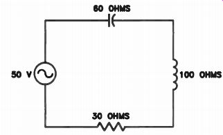
Figure 1. A series circuit where the inductive reactance is greater
than the capacitive reactance.
Series Circuits
In the circuit of Fig.1, the capacitive reactance is 60 ohms at the frequency applied to the circuit.
The inductive reactance of the coil is 100 ohms.
Since the wire used in the circuit has resistance, we know that there must be some small resistance in the circuit. Let's represent this resistance with a 30-ohm resistor. First, find the impedance of the circuit, then find the current flow in the circuit and the voltage across each part in the circuit.
Inductive reactance has the opposite effect of capacitive reactance. In any circuit where both exist, they tend to cancel each other out. The total reactance in this circuit is 100 - 60 = 40 ohms, which appears as inductive reactance because the coil reactance is greater. Therefore, the impedance of the circuit can be found using this formula:
Z = V112 + ( XL - X e) 1
Substituting 30 for R, 100 for XL, and 60 for X c, we get:
Z = V301 + (100 - 60)z
= V900 + 1,600
- V2,500
. 50 ohms impedance
Since the voltage applied to the circuit is 50 volts (V), we know that the current, I, must be:
I - - 0 - 1 ampere (A) Z 50
This means that the voltage across the resistor ER will be:
ER = IR = 1 x 30 = 30 V
The voltage across the coil EL will be:
EL = IXL = 1 x 100 = 100 V
And the voltage across the capacitor Ec will be: Ec = IXc = 1 x 60 = 60 V
The important thing for you to notice in this example is that only 50 V are applied by the generator, but there are 60 V across the capacitor and 100 V across the coil. If we take an AC voltmeter and measure the voltage across these components, these are the voltage readings we get.
However, since the phase of the voltage across the coil leads the current phase, and since the voltage phase across the capacitor lags the current phase, we would measure 40 V total across the coil and capacitor together, because they cancel each other. Since the coil voltage is greater than the capacitor voltage, the voltage phase leads the current. This is the effect we get when the net reactance is inductive.
To add the reactive voltage across the coil and capacitor to the voltage across the resistor, we must use this formula:
ET = N/Et 1 + ( EL - Eci l
= \ 7302 + 401
= V900 + 1,600
= J2,500
= 50 V
Figure 2 is the same as Fig.1, except that the capacitive reactance is 100 ohms and the inductive reactance is 60 ohms. We use the same formula to find the impedance, but we subtract the inductive reactance from the capacitive reactance. The net reactance is again 40 ohms, the impedance 50 ohms, and the current 1 ampere.
There are 100 V across the capacitance and 60 V across the inductance. The net voltage across the two is 40 V, but since the capacitive voltage is larger, the voltage phase lags the current. Remember from these two examples that the voltage across the larger reactance deter mines whether the current phase leads or lags the voltage phase.
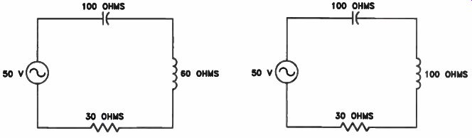
Figure 2. A series circuit where the capacitive reactance is greater
than the inductive reactance.
Figure 3. A series resonant circuit where the capacitive reactance is equal to the inductive reactance.
Resonant Circuits
In the series circuit shown in Fig.3, we again have a voltage of 50 V and a resistance of 30 ohms, but capacitive and inductive reactances are equal at 100 ohms. In this circuit, the inductive reactance of the coil exactly cancels the capacitive reactance of the capacitor. The only opposition to current flow is the 30-ohm resistor; thus, the impedance of the circuit is 30 ohms.
The current flow through the circuit is:
I = --- E = - 50 = 1.67 A Z 30
The voltage across the resistor is:
ER = IR = 1.67 x 30 = 50 V
The voltage across the coil is:
EL = IXL = 1.67 x 100 = 167 V
The voltage across the capacitor is:
Ec = IXc = 1.67 x 100 = 167 V
Notice that in this resonant circuit we have a voltage of 167 V (more than three times the generator voltage) across the coil, and across the capacitor. This step-up in voltage, called a resonant voltage step-up, occurs in all series resonant circuits. The lower the resistance in the circuit, the higher the resonant-voltage step-up.
Reducing the resistance value in the circuit from 30 ohms to 15 ohms will cause the circuit current to double and will also double the voltages across the coil and the capacitor. Remember, however, that these two voltages are 180° out of phase.
The voltage across the coil leads the circuit current by 90°, and the voltage across the capacitor lags the circuit current by 90 degrees. In combination, they cancel. A measurement of the total voltage across the coil and the capacitor will show 0 volts.
In the circuit shown in Fig.3, XL = Xc, because we know that: 1 XL = 2 pi fL and Xc - 2 pi fC We also know that: 1 2 pi fL = 2 pi fC We can rearrange this formula to get this: f2 . 1 4n-, LC If we take the square root of both sides of the equation, we get the formula for calculating the resonant frequency of an L-C circuit: 1 f - 2 pi /EC (Where f is the frequency in hertz (Hz) at which the circuit is resonant, L is the inductance in henrys (H), C is the capacity in farads (F), and 2n = approximately 6.28, a constant.) The relative position of the three parts in Fig.3 has no effect on the resonant circuit. As long as the inductive reactance is equal to the capacitive reactance, we have a series resonant circuit. In Fig.4(A), the positions of the coil and the resistor are interchanged, but the circuit is still a series resonant circuit. With a generator voltage of 50 V, a 30-ohm resistor, and the reactance of the coil and the capacitor each at 100 ohms, we have the same situation as in Fig.3.
Figure 4(B) shows the current waveform. The voltage across the resistor will be in phase with the current. Figure 4(C) shows the waveform of the voltage across the coil. Notice that it is leading the current by 90 degrees. In Fig.4(D), the waveform of the voltage across the capacitor is shown. Notice it is lagging the current by 90° and is 180° out of phase with the voltage across the coil. This is why the two voltages cancel.
Varying C, L, f, and R In the examples shown in Figs.1, 2, and 3, the lowest circuit impedance and the highest circuit current occurred at resonance. At resonance the circuit also acted like a purely resistive circuit, because the inductive and capacitive characteristics canceled out.
Both above and below resonance, circuit impedance is greater than at resonance. In Fig.1, where the inductive reactance is higher than the capacitive reactance, the circuit acts like a series circuit made up only of resistance and inductive reactance. In Fig.2, where the capacitive reactance is higher than the inductive reactance, the circuit acts like a series circuit made up of resistance and capacitive reactance. In either case, where the two reactances do not cancel completely, they add to the total impedance, making it higher than at resonance.
Varying C. Look at the circuit shown in Fig.5. At a frequency of approximately 500 Hz, the coil will have an inductive reactance of 314 ohms. If we start with zero capacitance in the circuit and begin increasing it in steps, the current varies as shown in Fig.6 on the next page.
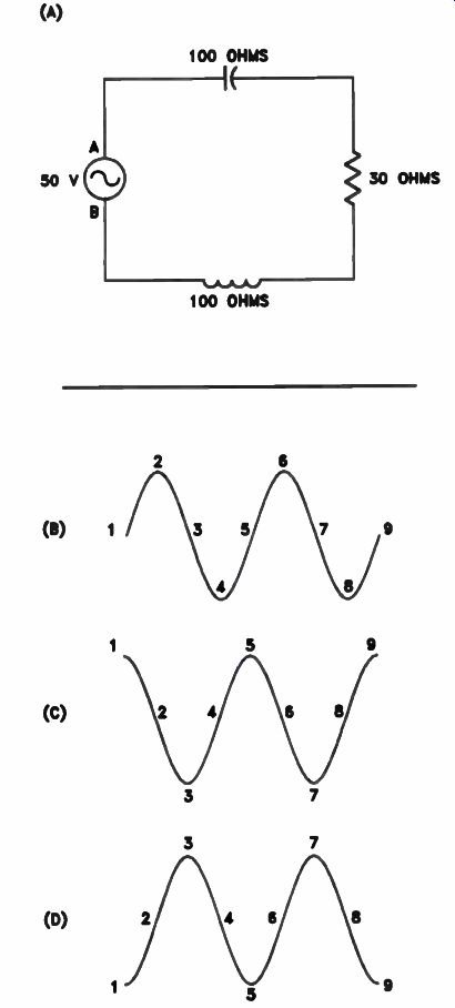
Figure 4. (A) Circuit. (B) Waveform of current and voltage across the
resistor. (C) Waveform of voltage across the coil. (D) Waveform of voltage
across the capacitor.
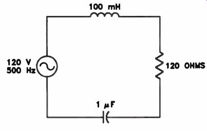
Figure 5. At 500 Hz, the 100 mH coil will have an inductive reactance
of 314 ohms and the 1 pF capacitor will have a capacitive reactance of
314 ohms, so it is a series resonant circuit.
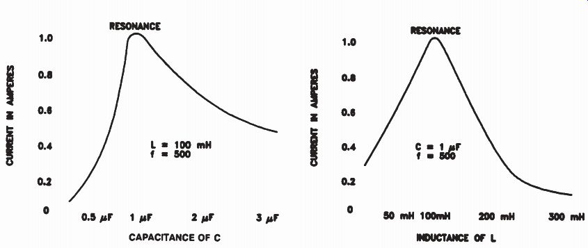
Figure 6. How current varies In a series resonant circuit when L is
100 mH, f Is 500 Hz, and C is varied from 0 to 3 microfarads.
Figure 7. How current varies in a series resonant circuit when C is 1 µF, f is 500 Hz, and L is varied from 0 to 300 millihenrys.
When capacitance is zero, there is an open circuit, so the current will be zero. As we add capacitance, the capacitive reactance decreases, until it reaches 314 ohms with a value of 1 microfarad (e). At this point, capacitive reactance equals inductive reactance, causing both to cancel. The current is limited only by the 120-ohm resistor in the circuit, making a current of 1 ampere.
As we increase capacitance beyond 1 uF, capacitive reactance continues to decrease. It be comes too small to cancel inductive reactance, leaving only resistance and inductive reactance in the circuit. The impedance increases above 120 ohms, and the current decreases as shown.
In either case, when capacitance is too little or too great for resonance, circuit impedance is greater than it is at resonance. The larger value of impedance reduces current flow in the circuit.
Notice also that below resonance, capacitive reactance is greater than inductive reactance, so the current phase in the circuit leads the voltage.
Above resonance, inductive reactance is greater than capacitive reactance, so the current phase lags the voltage.
Varying L. If we return to Fig.5 and insert a 1 le capacitor in the circuit, then vary the inductance from 0 to 300 millihenrys (mH), the current will vary as shown in Fig.7. When the inductance is zero, the capacitor has a reactance of 314 ohms in series with the 120-ohm resistor. There is a current flow of approximately 0.3 ampere.
As inductance increases in the circuit, the inductive reactance subtracts from the capacitive reactance until it reaches 100 mH, the point at which inductive reactance completely cancels capacitive reactance. The only limit on current under these conditions is the 120-ohm resistor, so current is maximum for the circuit. If inductance increases above 100 mH, inductive reactance exceeds capacitive reactance, impedance increases, and current decreases as shown.
For inductance values below 100 mH, the inductive reactance is not high enough to cancel the capacitive reactance, so the circuit acts capacitive, and the current phase leads the voltage phase. For inductance values above 100 mH, inductive reactance is greater than capacitive reactance, the circuit is inductive, and current phase lags the voltage.
Varying Both L and C. If we double the inductance to 200 mH, the inductive reactance doubles, increasing to approximately 630 ohms.
If we reduce the capacitance to 0.5 uF, capacitive reactance also doubles to 630 ohms. The inductive reactance is again equal to the capacitive reactance, making the circuit resonant at 500 hertz.
Many different values of coils and capacitors can be combined to obtain a circuit that is resonant (sometimes we say that it "resonates") at 500 hertz. Any value of coil that we might select will have a certain inductive reactance at a frequency of 500 hertz. We would need a capacitor with an equal capacitive reactance at 500 Hz to give us a circuit resonant at 500 hertz.
Varying f. If we vary the frequency applied to the combination of 100 mH coil and 1 uF capacitor, circuit current varies like the curve shown in Fig.8. At zero frequency there is no current flow because DC will not flow through the capacitor. As frequency increases, current increases.
This happens because, even though capacitive reactance decreases at the same rate that inductive reactance increases, greater proportions of each type of reactance cancel out, thereby reducing the total reactance in the circuit. At resonant frequency (500 Hz), the inductive reactance equals the capacitive reactance, and the two cancel completely, leaving minimum impedance and maximum current flow.
Above the resonant frequency, capacitive reactance continues to decrease, while inductive reactance continues to increase. The percentage of reactance cancellation decreases, because the amount of cancellation can only be as high as the smaller value of reactance. Therefore, the total reactance in the circuit increases. This means that the impedance in the circuit increases and, as a result, current flow in the circuit decreases.
Varying R. Under certain circumstances, the total resistance in the circuit can vary. As the resistance in the circuit changes, the Q of the circuit changes, as does current flow. The Q of a resonant circuit is equal to the inductive or capacitive reactance divided by the resistance in the circuit. In most resonant circuits, the only resistance in the circuit is the resistance in the wire used to wind the coil, so, in most cases, the Q of a resonant circuit will be equal to the Q of the coil. Remember that the Q of a coil is equal to its inductive reactance divided by its resistance.
Figure 9 on the next page shows three current curves where resistance is varied. Curves A and B have the same capacitor and inductor values with different resistances. Notice that Curve B, where DC resistance is lower, has a higher current and a sharper peak at resonance. Since the resistance in the circuit is lower, the circuit Q is higher. These are two characteristics of a high Q circuit: high current and a sharp resonance peak.
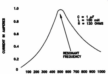
Figure 8. How current varies in a series resonant circuit when C is
1 uF, L is 100 mH, R is 120 ohms, and f is varied from 0 to 1,000 hertz.
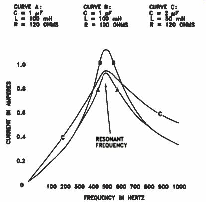
Figure 9. How the current varies in a series resonant circuit when f
is varied. In each case the product of L and C is the same, and resonance
occurs at 500 hertz.
A series resonant circuit can be used to select one frequency and reject all others. This is a form of tuning to a frequency. A high-Q circuit does a much better job than a low-Q circuit. Sometimes, however, a series resonant circuit is used to select a band (range) of frequencies rather than one particular frequency. In this case, a low-Q series resonant circuit will do a better job than a high-Q circuit, since the low-Q output current over a range of frequencies is higher, rather than a sharp peak of current over a narrow range.
The curve marked "C" in Fig.9 is the one we would obtain for a 50 mH coil, a 2 1.IF capacitor, and a series resistance of 120 ohms. Compare Curve C with Curve A. Notice that Curve A is considerably sharper than Curve C. This is Because the inductance in Curve A is greater than the inductance in Curve C, even though the resonant frequency is the same. The ratio of inductance to capacitance in a resonant circuit is called the LC ratio. In a series resonant circuit, a high LC ratio provides a sharper resonance curve than a low LC ratio.
Review
The most important thing to remember about a series resonant circuit is that at resonance the inductive and capacitive reactances will cancel.
The circuit acts like a low resistance and draws a high current, and the current will be in phase with the generator voltage. The voltage across the coil and the voltage across the capacitor can be several times the generator voltage. This increased voltage is called a resonant-voltage step-up.
Below resonance, the voltage across the capacitor is greater than the voltage across the coil, so the current phase leads the voltage phase. Above resonance, the voltage across the coil is greater than the voltage across the capacitor, so the phase of current lags that of the voltage.
Self-Test Questions
1. What is a resonant circuit?
2. Why is the current maximum at resonance in a series circuit consisting of a coil, a capacitor, and a resistor?
3. In a series resonant circuit, how will the phase of the voltage across the various components compare with the phase of the current flow in the circuit?
4. When a coil and a capacitor are connected in series and the frequency of the voltage applied to them is varied, at what point will the current flow through the circuit reach its maximum value?
5. What effect will reducing the resistance in the circuit have on the current flow in a series resonant circuit?
-----------------
PARALLEL RESONANT CIRCUITS
In a parallel resonant circuit, the coil and capacitor are in parallel. Like the series resonant circuit, the inductive reactance and the capacitive reactance are equal, and one cancels the other. However, the similarity ends at this point, because in most respects, the behavior of a parallel resonant circuit is opposite to that of a series resonant circuit. The energy stored in the capacitor and the coil circulates back and forth in the resonant circuit, alternately charging and discharging the capacitor, and building and collapsing the magnetic field of the coil.
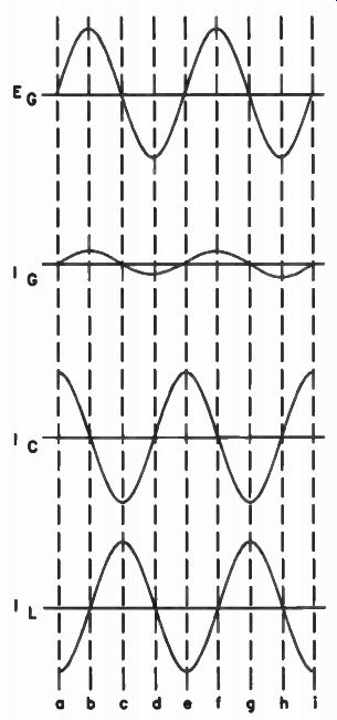
Figure 10. Voltage and current waveforms for parallel resonant circuit
in Fig.11.
Current Flow
Figure 10 shows the waveforms for a typical parallel resonant circuit, such as the one shown in Fig.11 on the next page. When the coil and capacitor are in parallel, resonance occurs when the branch currents through the parallel capacitor and coil are equal and opposite. Minimum current flows in the main line, as compared to maximum current for series-resonance, as the reactances cancel each other. Because the values of inductive and capacitive reactance are essentially equal at resonance, the currents in the branches of the parallel network are also equal.
Since line current is minimum, total circuit impedance is at maximum, by definition.
Let's perform some useful calculations, using the values listed for the coil, capacitor, and voltage given in Fig.11. The resonant frequency for a 0.1 uF capacitor and a 100 mH coil is equal to:
1/ f - 2pi/LC
1
= 6.28 x 0.0001
= 1,592 Hz
The resonant frequency is rounded off to the nearest hertz. At resonance, the capacitive and inductive reactance values should be equal.
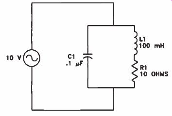
Figure 11. A parallel resonant circuit.
Again, we will round off the decimal places in the calculation and obtain these measurements:
Capacitive reactance: 1 X,- 27Tfc 1 6.28 x 1,592 x 0.0000001
= 1,000 ohms Inductive reactance: XL = 2:rfL
= 6.28 x 1,592 x 0.1
= 1,000 ohms
We can use these reactance values to calculate the branch currents. That is, current in the inductive branch is equal to the source voltage divided by the reactance, or 10/1,000 = 10 milli amperes (mA). (We will ignore the 10 ohm resistance since it is so low it will not have a significant effect.) We get the same current in the capacitive branch.
We have equal currents, but are they opposite? Well, since this is a parallel AC circuit, the current phase in the capacitive branch leads the source voltage phase by 90°, while the current phase in the inductive branch lags the source voltage by 90 degrees. A series circuit would show a cumulative phase difference, but in the parallel circuit the source voltage is applied equally across the network of the two reactive elements, producing a total phase difference of 180°, or directly opposing. Thus, the reactance currents cancel each other in the main line, although they circulate in the parallel network at a flow of 10 mA, as calculated above.
Below resonant frequency, there is more current in the main line and more current in the inductive branch because of the lower reactance of the coil at lower frequencies. Above the resonant frequency, reactance in the capacitive branch decreases, and current in the main line and in the capacitive branch increases.
What is the current in the main line at the resonant frequency of the parallel network? In theory, a perfect capacitor and a perfect coil would retain 100% of the circuit energy, charging and discharging each other back and forth, in definitely. Theoretically, the main line current would be zero because such a perfectly resonant circuit would create an infinite impedance.
There is no such thing as a perfect coil, however. There are losses due to the resistance of the wire used to wind the coil and for other reasons. These small losses are represented by the 10-ohm resistor shown in series with the inductive branch. As you know, this resistance determines the Q of the coil. There are also some very small losses in the capacitor, but normally the circuit Q is considered to be equal to the Q of the coil.
The shortcut way to calculate the line impedance presented by the parallel resonant network is to multiply the Q of the circuit times the inductive reactance. For the circuit shown in Fig.11, the Q is equal to the inductive reactance divided by the resistance, or: The parallel resonant total impedance is then:
Zr = XL x Q
= 1,000 x 100
= 100,000 ohms
If you are reasonably confident that you know the Q of the circuit, the shortcut method provides a usable ballpark figure for total impedance.
However, the resonant impedance may be directly and accurately measured by making a rough calculation according to the Q of the circuit, then placing a variable resistor of comparable range in series with the resonant circuit, as shown in Fig.12. Tune the circuit to resonance by varying the frequency of the applied voltage and watching for a sharp dip in the main circuit current, indicating that the impedance of the parallel resonant circuit is maximum. Carefully adjust the variable resistor so that the voltage drop across it is equal to the voltage drop across the parallel resonant network. Disconnect the variable resistor from the circuit and measure its resistance. The resistance is equal to the impedance of the resonant network, since equal voltage drops in a series circuit mean equal resistance values.
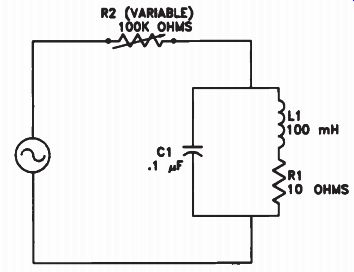
Figure 12. Using variable resistor to calculate impedance of L1-C1 resonant
network.
Varying C, L, f, and R in a Parallel Resonant Circuit
When we speak of resistance in a parallel resonant circuit, we are usually referring to losses in the circuit that act like a resistor connected across the circuit (sometimes called shunt resistance), or a small resistance in series with the coil, as discussed previously. This resistance is sometimes called AC resistance and is a result of eddy currents, flux leakage, skin effects, hysteresis losses, and other factors that we will discuss in a later lesson.
Varying C. At resonance, the inductive reactance is equal to the capacitive reactance in the parallel resonant circuit, just as in a series resonant circuit. What if the generator shown in Fig.11 had a frequency of 500 Hz and the coil had an inductance of 100 millihenrys? Figure 13 on the next page shows the effect on line current of different capacitor values. When capacitance is zero, the only limit to the flow of current is the coil impedance and coil AC resistance.
With zero AC resistance, the inductive reactance is 314 ohms. With a generator voltage of 120 V, the current is 0.38 ampere. As capacitance increases toward 1 !I F , current decreases to a minimum because the circuit resonates at that point, and main circuit impedance is maximum.
As capacitance increases beyond 1 µF, circuit impedance goes down and line current goes up. In the example shown, when the capacitance is less than 1 µF, most of the current flows through the coil. With zero capacitance, the current should lag the generator voltage by an angle close to 90 degrees. As we approach resonance, the current begins to fall into phase with the voltage, until at resonance the main line current is in phase with the voltage.
Varying L. If we change only the inductance in the circuit, we will find that we get an effect similar to that of changing the capacitance. The line current increases when the inductance is either too large or too small for resonance. If the inductance is below the value needed for resonance, the circuit acts exactly as it does when too low a capacitance is used. Similarly, when the inductance is too high for resonance, the circuit acts as it does when the capacitance is too high.
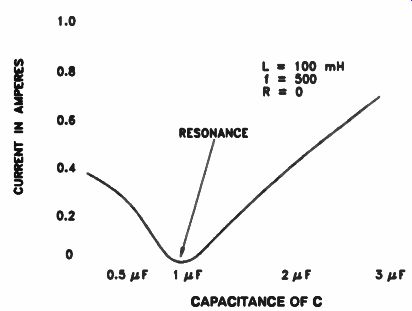
Figure 13. How the line current varies when the capacitance of the capacitor
In a parallel resonant circuit is varied.
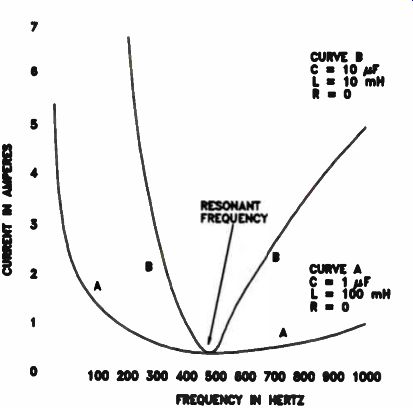
Figure 14. How the line current varies when the frequency is varied in a parallel resonant circuit.
Varying f and R. What if the resistance R in Fig.11 were zero? Curve A in Fig.14 shows how the current will vary as the frequency applied to the resonant circuit is changed. When the frequency is zero, we have dc. No current will flow through the capacitor. At the same time, the inductive reactance of the coil is zero, so the only limit to current flow will be the resistance of the coil. As the frequency is increased beyond the resonant frequency, the current rises slowly. The increased line current is due to the drop-off in the capacitive reactance of the capacitor. Current flow through the coil will continue to decrease as the frequency is increased because the inductive reactance of the coil will increase with the frequency.
At a frequency below the resonant frequency of the circuit, most of the current flows through the coil, and the parallel resonant circuit is inductive. At resonance the circuit acts like a high resistance. Above the resonant frequency, the current flow through the capacitor is greater than the current flow through the coil, so the circuit is capacitive.
Curve A in Fig.14 is for a circuit composed of a 100 mH coil and a 11.1F capacitor. This circuit resonates at 500 hertz. If we reduce the inductance to 10 mH and increase the capacitance to 10 µF, the resonant frequency remains 500 Hz, because the product of the inductance and capacitance is the same. A 20 mH coil and a 5 µF capacitor also resonate at a frequency of 500 Hz, for the same reason, as are a 10 mH coil and a 10 uF capacitor.
Curve B of Fig.14 shows the line-current curve for a parallel resonant circuit made up of a 10 mH coil and a 10 1.1F capacitor. Notice that the current rises much faster on both sides of resonance and drops to zero much more sharply than the curve for the 100 mH coil and the 1 uF capacitor. Curve B is sharper than curve A. Because the circuit of curve B has a lower ratio of inductance to capacitance. The L/C ratio for curve A is 10 times higher than the L/C ratio for curve B. A low L/C ratio gives a sharp curve.
Parallel resonant circuits with a low L/C ratio are used to separate signals on frequencies that are close together. Parallel resonant circuits with a high L/C ratio are used to pass a band of frequencies. As you can see from Fig.14, if we want to pass a band of signals from 300 Hz to 800 Hz, the higher L/C-ratio resonant circuit is more suitable. On the other hand, if we want to separate a 500 Hz signal from a 300 Hz signal, the low L/C-ratio circuit would be better.
The Q of a coil is another factor that affects the sharpness of the resonant curves. A high-Q coil will yield a much sharper curve than a low-Q coil.
In a series resonant circuit, we obtain a sharp response curve with a high L/C ratio. We have the opposite situation in a parallel resonant circuit, where we obtain a sharp curve with a low L/C ratio.
Review
The parallel resonant circuit acts like a high resistance. The line current is low and in phase with the generator voltage. The current flowing back and forth between the capacitor and the coil in the resonant network is much higher than the generator current. Below resonance, the inductive reactance is less than the capacitive reactance, so more generator current flows through the coil, and the current phase lags the generator voltage.
Above resonance, the capacitive reactance is less than the inductive reactance, so more generator current flows through the capacitor than the coil, and the current phase leads the voltage.
Self-Test Questions
6 How do you distinguish between a series resonant and a parallel resonant circuit?
7 What does a parallel resonant circuit act like at resonance?
8 Does the generator supply a current of high value or of low value to a parallel resonant circuit?
9 In circuits such as the one shown in Fig.11, why will the voltage across the 10-ohm resistor be small?
10 Does a current of high value or low value flow in the coil and capacitor in a parallel resonant circuit?
11 Will increasing the resistance of the coil in a parallel resonant circuit cause the generator current to increase or decrease?
12 If a parallel resonant circuit is used in a radio receiver to select one signal and reject others, do you want a high L/C ratio or a low L/C ratio?
--------------
COMPARISON OF RESONANT CIRCUITS
Series resonant and parallel resonant circuits are found in most electronic equipment that re quires tuning or filtering. Table I compares and summarizes the important characteristics of series resonant and parallel resonant circuits. Notice that in many cases the series resonant circuit acts opposite to a parallel resonant circuit.
The resistance, or impedance, at resonance and the current at resonance are very important factors. A series resonant circuit acts as a low resistance at resonance, and the current flowing through it is relatively high. On the other hand, a parallel resonant circuit acts as a very high resistance at resonance, and the current flowing through it is very low.
The combination of the coil and the capacitor in a resonant circuit is often called a tank circuit.
A tank circuit stores electricity just as a water tank stores water. The current flowing between the coil and capacitor is called the tank current.
In a series resonant circuit, the tank current is the line current, and it is high. In a parallel resonant circuit, even though the line current is low, the tank current will be high.
Resonance Curves
In Fig.14, we used a small coil and a large capacitor to obtain a sharp resonance curve with a parallel resonant circuit. This gave us a low L/C ratio. For a sharp resonant curve in a series resonant circuit, you use the opposite: a large inductance and a small capacitance. This is simply another example of the difference between series resonant and parallel resonant circuits. As a technician, you will not be called upon to design a series resonant circuit or a parallel resonant circuit, but the more you understand about the circuits, the better you will be able to maintain equipment for which you might be responsible.
Identifying Resonant Circuits
Sometimes, it is not easy to distinguish between a series resonant and a parallel resonant circuit. Figure 15(A) on page 16 shows a series resonant circuit. Remember that a series resonant circuit is a resonant circuit in which the source voltage is applied across the coil and the capacitor in series. There is no doubt that this is a series resonant circuit.
In Fig.15(B) is a parallel resonant circuit. A parallel resonant circuit is a resonant circuit in which the source voltage is applied to the coil and capacitor in parallel. It is easy to see that this is a parallel resonant circuit.
In Fig.15(C) there are two resonant circuits that look like parallel resonant circuits. The voltage from the generator is applied to the first circuit, which we call the primary. The second resonant circuit is arranged so that the coil is inductively coupled to the coil of the first or primary circuit. This circuit is called the secondary circuit.
Now, looking at the primary, we see that the generator is connected across both the coil and the capacitor. There is no doubt that the voltage is applied to the two in parallel and that therefore the circuit must be a parallel resonant circuit. But what about the secondary? Since the coil and capacitor are connected in parallel, you might jump to the conclusion that the secondary also is a parallel resonant circuit.
----------------------
TABLE 1 COMPARISON OF RESONANT CIRCUITS
------------
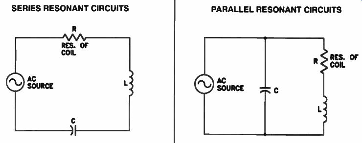
SERIES RESONANT CIRCUITS
1 The coil, the capacitor, and the AC voltage source are all in series.
2 Resonance occurs when the reactance of L is equal to the reactance of C. 3 At resonance, source current is at a maximum (very high). 4 At resonance, a series resonant circuit acts like a resistor of low ohmic value.
5 At resonance, the voltages across L and C are equal in magnitude but 180° out of phase with each other.
6 At resonance, the same current flows through the en tire circuit.
7 At resonance, the voltage across either L or C may be greater than that of the source, giving resonant voltage step-up.
8 At resonance, increasing the value of coil resistance R lowers the circuit current, thereby lowering the resonant-voltage step-up.
9. Off resonance, the circuit acts like that part which has the higher reactance.
a. Increasing C above its at-resonance value makes the circuit act like a coil.
b. Reducing C below its at-resonance value makes the circuit act like a capacitor.
c. Increasing L above its at-resonance value makes the circuit act like a coil.
d Reducing L below its at-resonance value makes the circuit act like a capacitor.
e Applying a higher frequency than the resonant one makes the circuit act like a coil.
f. Applying a lower frequency than the resonant one makes the circuit act like a capacitor.
10 The product LC is constant for any given resonant frequency.
11 Increasing L or increasing C lowers the resonant frequency.
12 Decreasing L or decreasing C raises the resonant frequency.
13 The Q factor of the circuit is essentially equal to the coil reactance divided by the AC resistance of the coil.
---------------
PARALLEL RESONANT CIRCUITS
1. The coil, the capacitor, and the AC voltage source are all in parallel.
2 Resonance occurs when the reactance of L is equal to the reactance of C.
3 At resonance, source current is at a minimum (very low).
4. At resonance, a parallel resonant circuit acts like a resistor of high ohmic value.
5. At resonance, the voltages across L, C, and the source are all the same in magnitude and phase.
6. At resonance, the currents through L and C are essentially equal in magnitude but are 180° out of phase.
7 At resonance, the current through either L or C is greater than the source current, giving resonant current step-up.
8. At resonance, increasing the value of coil resistance R increases the current, thereby lowering the resonant-current step-up.
9. Off resonance, the circuit acts like that part which has the lower reactance.
a. Increasing C above its at-resonance value makes the circuit act like a capacitor.
b Reducing C below its at-resonance value makes the circuit act like a coil.
c. Increasing L above its at-resonance value makes the circuit act like a capacitor.
d. Reducing L below its at-resonance value makes the circuit act like a coil.
e. Applying a higher frequency than the resonant one makes the circuit act like a capacitor.
f. Applying a lower frequency than the resonant one makes the circuit act like a coil.
10. The product LC is constant for any given resonant frequency.
11. Increasing L or increasing C lowers the resonant frequency.
12. Decreasing L or decreasing C raises the resonant frequency.
13. The Q factor of the circuit is essentially equal to the coil reactance divided by the AC resistance of the coil.
----------------------
----------------------
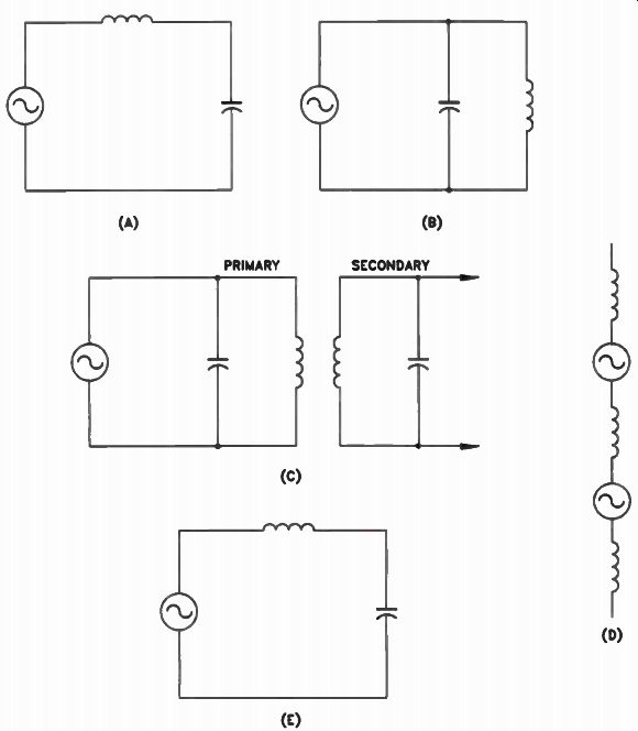
Figure 15. (A) A series resonant circuit. (6) A parallel resonant circuit.
(C) The primary of the transformer and the capacitor across it form a
parallel resonant circuit, and the secondary of the transformer and its
capacitor form a series resonant circuit. (D) Generators and coils connected
in series. (E) The equivalent of the secondary circuit.
Actually, how the coil and capacitor are connected has no bearing on whether the circuit is series resonant or parallel resonant. Remember, we said that in a parallel resonant circuit the voltage is applied across the coil and the capacitor in parallel, and in the series resonant circuit the voltage is applied to the coil and capacitor in series. This is what distinguishes a series resonant circuit from a parallel resonant circuit.
In the secondary circuit shown in Fig.15(C), the voltage is induced in the secondary. Actually, some voltage is induced in each turn of the coil, and the coils act as if they are connected in series, so that the total voltage induced in the secondary is the sum of the voltages induced in each turn.
We can compare this to a number of small generators connected in series with the various turns of the coil, and the coil might look like Fig.15(D). The voltage induced in the coil is actually applied in series with the turns of the coil, rather than in parallel with the coil and capacitor. The circuit could be represented by Fig.15(E), which is the same as Fig.15(A). Therefore, the secondary of the transformer shown in Fig.15(C) is a series resonant circuit and not a parallel resonant circuit.
You will find this type of double-tuned circuit in many pieces of electronic equipment. In these circuits, the voltage is always applied across the primary winding in parallel with the coil and capacitor, so the primary circuit is always a parallel resonant circuit. The voltage in the secondary is always induced in the turns of the secondary winding, and this circuit is always a series resonant circuit.
When we discussed parallel resonant circuits, we pointed out that the tank circuit current will be much higher than the generator current. This is called a resonant-current step-up. In series resonant circuits, there is a resonant-voltage step-up. Therefore, in double-tuned transformers like the one shown in Fig.15(C), there is resonant-current step-up in the primary and a resonant-voltage step-up in the secondary.
Resonant-current step-up causes the primary winding to produce more flux, and more lines of flux cut the secondary winding on the transformer, inducing a higher voltage in it. At the same time, the resonant-voltage step-up occurring in the secondary circuit creates a voltage across the output of the transformer that is much higher than the generator voltage. In the input stages of electronic equipment, we often deal with signals of only a few microvolts. Resonant-current step-ups and resonant-voltage step-ups help amplify these weak signals to strong, useful levels.
Review
Both series resonant and parallel resonant circuits act like pure resistances. However, the series resonant circuit acts like a low resistance.
The current flowing through the generator, coil, and capacitor is the same, but the voltage across the coil and the voltage across the capacitor will be much higher than the generator voltage.
The parallel resonant circuit acts like a very high resistance, and the voltage across the generator, coil, and capacitor is the same. However, the current flowing in the coil and capacitor is much higher than the generator current.
Below resonance, a series resonant circuit acts like a capacitor, and the current leads the applied voltage. A parallel resonant circuit, on the other hand, acts like an inductance below resonance, and the current lags the generator voltage. Above resonance, a series resonant circuit acts like an inductance, and the current lags the generator voltage. In the same condition, a parallel resonant circuit acts like a capacitor and the current leads the generator voltage.
Self-Test Questions
13. Explain the difference between the current flowing in a coil and capacitor in a series resonant circuit, and the current flowing in the coil and capacitor in a parallel resonant circuit.
14. Explain the difference between the voltage across the coil and capacitor in a series resonant circuit and the voltage across the coil and capacitor in a parallel resonant circuit.
15. What is the difference between the genera tor current in a series resonant circuit and in a parallel resonant circuit? 16 How can the voltage across the coil or capacitor in a series resonant circuit be greater than the source voltage? 17 Will the voltage across the coil or the capacitor in a high-Q series resonant circuit be greater than the voltage across the coil or capacitor in a low-Q series resonant circuit?
---------------
HOW RESONANT CIRCUITS ARE USED
Resonant circuits are used in most radio and TV receivers, where these circuits select the broadcast signal from a station operating on a specific frequency but reject signals from other stations operating on different frequencies. Resonant circuits are also used as frequency filters in many applications.
There are three basic types of filters. A low pass filter can pass frequencies up to a certain level, but block higher frequencies. A high-pass filter allows signals above a certain frequency to pass through it readily. The third type of filter, a band-pass filter, passes a group of frequencies that lie between a defined low and high extreme, but rejects frequencies above or below the limits.
Selecting a Desired Signal
Every coil and capacitor combination is resonant at some frequency. For example, we found that a 100 mH coil will form a resonant circuit with a 1 ;IF capacitor at a frequency of 500 Hz, because at that frequency the inductive reactance of the coil is equal to the capacitive reactance of the capacitor.
Suppose, however, that instead of using a 1 µF capacitor, we use a 0.5 uF capacitor. The 0.5 µF capacitor will have twice the reactance of the 1 uF capacitor, so the capacitor coil combination will not be resonant at 500 hertz. If we increase the frequency of the signal applied to the circuit, the reactance of the capacitor will start coming down and the reactance of the coil will start going up. At a frequency of about 712 Hz, the two will be equal, and the circuit will be resonant at that frequency. Therefore, to be able to select--signals over a band of frequencies, all we have to do is use either a variable coil or a variable capacitor.
Figure 16 shows a typical circuit found in the input section of a radio receiver designed for use in the standard AM broadcast band. Notice that two coils are placed close together so that they are inductively coupled. They actually form a transformer. The triangular symbol connected to the primary winding is the symbol used for an antenna.
The antenna picks up signals from many stations operating in the standard broadcast band and signals from stations operating outside the band. The radio waves striking the antenna cause a very small current to flow through the primary winding L1 of the transformer, setting up a varying flux that cuts the turns of L2 and induces a voltage in series with it. At some frequency, the combination of L2 and the capacitor will form a series resonant circuit. There will be a high circulating current at this frequency and a resulting resonant-voltage step-up across L2 and across C.
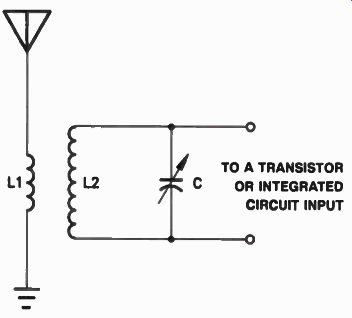
Figure 16. Input circuit of a radio receiver.
The signal you tune in will be much stronger than other signals because of this resonant voltage step-up. Radio frequency signals of a higher frequency will be bypassed by the low reactance of the capacitor. Radio frequency signals below the resonant frequency will be bypassed by the low reactance of L2. The one signal operating at the resonant frequency will be much stronger than all others.
In the crowded commercial broadcast bands, one resonant circuit is not sufficient to select a single signal frequency and reject all others.
Additional resonant circuits are used to provide additional selectivity. Selectivity is defined as the ability of a circuit to select a signal while rejecting all others.
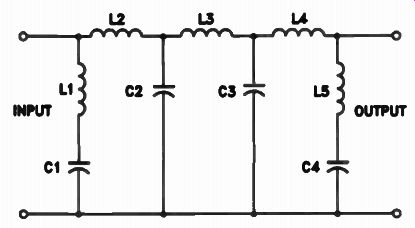
Figure 17. A low-pass filter.
How Filters Are Used
Two important terms related to filters are attenuation and cutoff frequency Attenuation tells you how much a filter reduces the signal strength. The cutoff frequency tells you the frequency at which the filter becomes effective.
Low-Pass Filters. An example of a low-pass filter is shown in Fig.17. This filter is designed to pass frequencies below the cutoff frequency and to attenuate frequencies above the cutoff frequency. At the input of the filter is a series circuit made up of L1 and C1. This circuit is resonant above, but very close to, the cutoff frequency C1 and L1 are in parallel to the incoming signal voltage. Any signal voltage that is developed across L1 and C I is passed on; it is not filtered out. Sometimes we say that voltage dropped across a parallel resistance or reactance is developed, as compared to a series component, where the voltage drop tends to attenuate the voltage, or use it up.
Below the cutoff frequency, the reactance of C1 is higher and signal voltage is dropped, or developed, across the capacitor. This voltage appears at the filter output; that is, the voltage is not filtered out. If the voltage is not developed across the capacitor or the coil, it disappears into the internal resistance of the circuit or antenna from which it came.
L2 is in series. Signal voltage dropped across L2 is reduced to some degree; it is attenuated, filtered. At frequencies below resonance, the reactance of L2 is low and the reactance of C2 is high, so that very little signal is lost across L2.
Since C2 is in parallel, signal voltage that is dropped across C2 does appear at the output and is not filtered out by C2.
L3 and C3 are also resonant at some frequency above the cutoff frequency Below the cutoff frequency, the reactance of L3 is low and the reactance of C3 is high, so there is very little attenuation of signals below the cutoff frequency.
Above the cutoff frequency, the reactance of L3 becomes high and the reactance of C3 goes down, so that the signal is greatly attenuated because it is not dropped, or developed by C3 in parallel, while at the same time it is dropped and reduced by L3 in series.
L4 provides additional attenuation for signals above the cutoff frequency. The combination of L4, L5, and C4 forms a series resonant circuit at a frequency somewhat above the cutoff frequency. L5 and C4 form another series resonant circuit at a frequency still higher, to further attenuate signals above the cutoff frequency.
High-Pass Filters. Figure 18 is a diagram of a high-pass filter. This filter is designed to pass signals above the cutoff frequency and to attenuate signals below the cutoff frequency.
Here we have L1 and C1 resonant at some frequency below the cutoff frequency to attenuate signals close to, but below, the cutoff frequency. Since they are in parallel to the signal path, they attenuate frequencies by having low reactance, so that the signal frequency does not appear, or develop across the coil or capacitor.
Above the cutoff frequency, the reactance of L1 becomes high, so that high-frequency signals are not attenuated.
Above the cutoff frequency, the reactance of C2 and the reactance of C3 is low and the reactance of L2 and L3 is high, so they pass signals with little attenuation. Below the cutoff frequency, the reactance of C2 and C3 is high and the reactance of L2 and L3 is low, so they greatly attenuate signals.
C4, L4, and C5 form a series resonant circuit that is resonant below the cutoff frequency L4 and C5 also form a series resonant circuit that is resonant below the cutoff frequency. These two series circuits attenuate signals below the cutoff frequency. Above the cutoff frequency, the reactance of L4 is high, so signals are not attenuated.
Band-Pass Filters. Figure 19 is a diagram of a band-pass filter. This type of filter is designed to pass a band of frequencies. Suppose, for example, we want to pass a band of frequencies between 9 and 11 megahertz (MHz). This filter would be designed to pass frequencies within this band with little or no attenuation and to attenuate signals below 9 MHz and above 11 megahertz.
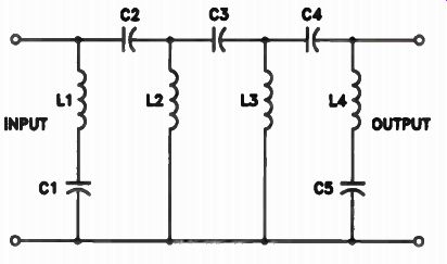
Figure 18. A high-pass filter.
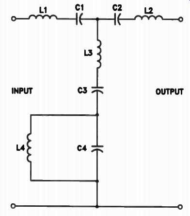
Figure 19. A band-pass filter.
In this filter, L1 and C1, L2 and C2, L3 and C3 all form series resonant circuits resonant at 10 megahertz. L4 and C4 form a parallel resonant circuit also resonant at 10 megahertz. The series resonant circuits are designed with a fairly low LC ratio to pass signals above 9 MHz and below 11 megahertz. The parallel resonant circuit is designed with a high LC ratio to produce a broad curve, which offers a high impedance to signals within the pass-band.
Below 9 MHz, the reactance of C1 and the reactance of C2 begin to increase and offer considerable opposition to signals below these frequencies. Since L3 and C3 are a low L/C ratio, they don't offer much opposition to signals immediately below 9 megahertz. However, the impedance of the parallel resonant circuit decreases below 9 MHz and much of the signal would pass through C4 and L4.
Above 11 MHz, L 1 and L2 begin to offer considerable opposition to the signal. Again, with the low LC ratio and the combination of L3 and C3, the signal passes through this combination and then through C4, whose reactance has decreased. Thus, signals above and below the de sired pass-band are attenuated, while signals within the pass-band would pass easily.
Review
Resonant circuits are used to select one signal frequency and reject all others. Resonant circuits are also used in filters. Remember that a low-pass filter is a filter that will pass all signal frequencies below the cutoff frequency and block all signals above it. A high-pass filter is a filter that will block all signal frequencies below the cutoff frequency and pass all signal frequencies above the cutoff frequency. A band-pass filter is a filter that will pass a band of frequencies. It will reject all signals below or above the pass band.
Self-Test Questions
18 Is the resonant circuit made up of L2 and C in Fig.16 a series resonant circuit or a parallel resonant circuit?
19 What is a low-pass filter?
20 What is a high-pass filter?
21 What is a band-pass filter?
ANSWERS TO SELF-TEST QUESTIONS
1 A resonant circuit is one in which the inductive reactance equals the capacitive reactance.
2 The current is maximum because the inductive reactance cancels the capacitive reactance and the impedance of the circuit is at a minimum.
3 Across the resistor the voltage will be in phase with the current; across the coil it will lead the current by 90°; across the capacitor it will lag the current by 90 degrees.
4 The current will reach its maximum value when the inductive reactance of the coil cancels the capacitive reactance of the capacitor. When this happens we have a series resonant circuit.
5 Reducing the resistance in a series resonant circuit will cause the current flow in the circuit to increase. A higher resonant voltage will appear in turn across the coil and the capacitor. The voltage that appears across the resistor will remain the same, Because the increase in current will be counteracted by the reduction in the resistance.
6 The distinction between a series resonant and a parallel resonant circuit lies in the way in which the voltage is applied to the coil and capacitor. If it is applied to the coil and capacitor in series, this circuit is series resonant; if it is applied to the coil and capacitor in parallel, the circuit is parallel resonant.
7 A high resistance.
8 The generator connected across a parallel resonant circuit will supply a current of low value because the high resistance of this type of circuit limits the current that can flow.
9 The voltage across the resistor will be small because the resistor is in series with the parallel resonant circuit. A parallel resonant circuit has a very high resistance at resonance and most of the voltage will be dropped across it. Consequently, there will be little voltage across the resistor.
10 A high-value current flows in the coil and in the capacitor.
11 Increasing the resistance of the coil in a parallel resonant circuit causes the genera tor current to increase. More losses occur as a result of the increased resistance, and the generator supplies more current to make up for these losses.
12 A low L/C ratio gives a sharper curve, such as curve B in Fig.14.
13 In a series resonant circuit, the same current flows in the coil and in the capacitor.
Since the generator, resistance, coil, and capacitor are all in series in a series resonant circuit, the same current must flow through all these components. On the other hand, in a parallel resonant circuit, the currents through the coil and capacitor are essentially equal in magnitude but are 180° out of phase.
14 In a series resonant circuit, the voltage across the coil will be equal to, but 180° out of phase with, the voltage across the capacitor. In a parallel resonant circuit, the coil and capacitor are connected in parallel and the voltage across the two will therefore be the same.
15 The generator current in a series resonant circuit will be very high because this circuit acts like a low resistance. The genera tor current in a parallel resonant circuit will be very low because this circuit acts like a high resistance.
16 The inductive reactance of the coil in a series resonant circuit cancels the capacitive reactance of the capacitor. Therefore, the only factor that limits current flow in the circuit is the resistance in the circuit. This results in a very high current flow. The current flowing through the coil and through the capacitor produces a voltage drop across these components that will be equal to the product of the current times the reactance of the part. This voltage may be greater than the source voltage.
17 Yes, the voltage across the coil and capacitor in a high-Q series resonant circuit will be greater because there will be a higher current flow.
18 The resonant circuit is a series resonant circuit because the voltage is induced in series with the turns of L2. Therefore, the voltage is applied in series with the coil and the capacitor.
19 A low-pass filter is a filter designed to pass signals below a certain frequency and reject signals above that frequency.
20 A high-pass filter is a filter designed to pass all signals above a certain frequency and to reject signals below that frequency.
21 A band-pass filter is a filter designed to pass a certain band of frequencies with little or no attenuation. It will reject or offer considerable opposition to frequencies above and below the band it is designed to pass.
-------------
Lesson Summary
Some of the important facts that you should remember about this lesson are ...
• Current in a series resonant circuit is maximum at the resonant frequency.
• Impedance in a series resonant circuit increases as frequency increases or decreases above and below the resonant point.
• Current in a parallel resonant circuit is minimum at the resonant frequency, except in the tank network, where current is maximum.
• Impedance presented by a parallel resonant circuit decreases as frequency increases or decreases above and below the resonant point.
• Both series and parallel resonant circuits can be carefully combined into filters that shunt (remove) or pass selected frequencies from a signal path.
This is Lesson Number 2224.
Make sure you print your name, student number, and lesson number in the spaces provided on the Lesson Answer Form. Be sure to fill in the circles beneath your student number and lesson number.
Reminder: A properly completed Lesson Answer Form allows us to evaluate your answers and speed the results and additional study material to you as soon as possible.
Do not hold your Lesson Answer Forms to send several at one time. You may run out of study material if you do not send your answers for evaluation promptly.
1. In a series resonant circuit, at resonance:
a. The impedance is at a maximum.
b. The impedance is at a minimum.
c. The coil current is at a minimum.
d. The capacitor current is at a minimum.
2. At resonance, a generator connected across a parallel resonant circuit will supply:
a. A high current.
b. The coil current.
c. The capacitor current.
d. A current to make up for the losses in the resonant circuit.
3. What is the impedance of a series resonant circuit having the following component values: R = 25 ohms, XL = 200 ohms, Xc = 200 ohms?
a. 25 ohms.
b. 200 ohms.
c. 400 ohms.
d. 425 ohms.
4. In a parallel resonant LC circuit, XL = 500 ohms and Xc = 500 ohms. The LC circuit is connected across a 150 V generator. The generator current is 0.1 ampere. What is the impedance of the parallel resonant LC circuit?
a. 500 ohms.
b. 1,000 ohms.
c. 1,500 ohms.
d. 2,500 ohms.
5. A series resonant circuit is made up of a resistor, a coil, and a capacitor, connected across a generator. The voltage across the resistor is 50 V, the voltage across the capacitor is 250 V, and the voltage across the coil is 250 volts. What is the generator voltage?
a. 50 volts.
b. 250 volts.
c. 500 volts.
d. 550 volts.
6. Below the resonant frequency, a series resonant circuit acts like:
a. A resistor.
b. A coil.
c. A capacitor.
d. A low impedance.
7. Below the resonant frequency, a parallel resonant circuit acts like:
a. A resistor.
b. A coil.
c. A capacitor.
d. A low impedance.
8. At resonance, both a series resonant and a parallel resonant circuit:
a. Act like a high resistance.
b. Act like a low resistance.
c. Act like a resistance.
d. Draw a low generator current.
9. When comparing series resonant and parallel resonant tank circuits, the current in the tank will be:
a. High only in the series circuit.
b. High only in the parallel circuit.
c. High in the series circuit, but low in the parallel circuit.
d. High in both types of resonant circuits.
10. A high-pass filter:
a. Passes frequencies below the cutoff frequency.
b. Attenuates frequencies above the cutoff frequency.
c. Attenuates frequencies below the cutoff frequency.
d. Attenuates frequencies above and below the band of frequencies it passes.
---------------
NRI Schools
GET ALONG WITH PEOPLE
A national magazine recently published the results of a survey in which it asked several hundred successful men and women:
" What single ability have you found to be most essential to your success?" Almost unanimously, the answer was: "The ability to get along with people." I'm sure you are already aware of the importance of this often under valued ability But did you think of getting along with others as a skill? It is a skill; one that you can learn like any other.
To be successful in any field--technical, artistic, or commercial--you must be able to get along with other people. You must have the ability to work with others to achieve your common goals. You can only profit from your special talents and skills if other people are willing to come to you for your services, and people won't seek you out if they don't like you.
Keep this in mind in your daily life. Practice getting along with people. Notice the things people respond to and the things that "turn them oft" There is always room for improvement in this area.
As you go along, you will learn what many happy and successful people already know--that getting along with others is the single most important factor in gaining or keeping success.
---------------------------