AMAZON multi-meters discounts AMAZON oscilloscope discounts
An oscillator circuit is used to generate an AC signal. It takes the DC from the power supply and converts it to ac. The frequency of the AC signal may be anywhere from a few hertz to thousands or even millions of hertz. The exact frequency at which the oscillator operates will depend upon the oscillator circuit and the values of the parts used in the circuit.
Oscillators can be divided into two types: LC and RC. LC oscillators use inductance and capacitance in the frequency-determining circuits. RC oscillators use resistance and capacitance in the frequency-determining network.
Both LC and RC oscillators work on the same basic principle, that of feeding some of the signal from the output circuit back into the input circuit. This signal is called the feedback signal and enables the oscillator to go on generating its own signal. The amount of signal that must be fed back into the input depends upon a number things, but it must always be strong enough to enable the oscillator to produce a signal that can overcome the losses in the oscillator circuit.
In addition to feeding enough energy from the output circuit back into the input circuit of the oscillator, the feedback signal must also be of the correct phase. This will enable the oscillator to produce a signal that will reinforce the signal in the oscillator output. If the feedback signal is not of the correct phase, it will oppose the signal in the output instead of aiding it, and the oscillator will stop oscillating.
RESONANT CIRCUITS
LC oscillators are used to generate high frequency signals. Perhaps the most important part of an LC oscillator is its resonant circuit.
Before we start studying LC oscillators, let's briefly review resonant circuits and learn some more important facts about them.
Damped Waves
If we connect a imam across a capacitor, the capacitor will charge to the battery voltage.
If we disconnect the battery from the capacitor, the capacitor will remain charged until we provide a circuit through which it can discharge.
If we connect a coil across the charged capacitor, at the instant we connect the coil, the voltage across it will be equal to the capacitor voltage, but the current flow in the circuit will be zero as shown in Fig.1(A). Immediately after the coil is connected across the capacitor, the capacitor will begin to discharge through the coil. The excess of electrons on side A of the capacitor will attempt to flow through the coil to get to side B. As a result, a current flow will be set up in the circuit, as shown in Fig.1(B). Remember that a coil opposes a change in the current flowing through it. So the capacitor cannot discharge instantly through the coil, but rather must build up a current in the coil, which in turn builds up a magnetic field around the coil. Eventually, the capacitor will build up a current flow in the coil and enough electrons will leave plate A and get to plate B to discharge the capacitor.
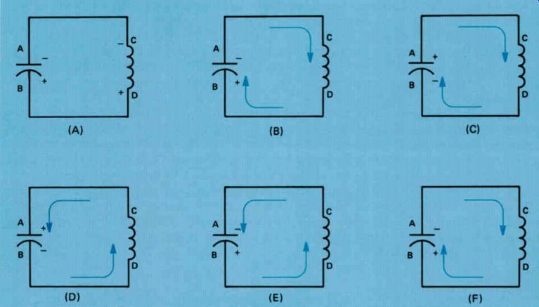
Figure 1. How oscillation takes place in a resonant circuit.
The instant the capacitor is completely discharged, the current does not stop flowing. This is due to the inductance of the coil. Remember, inductance is the quality of a coil that opposes any change in the current flowing through it.
The capacitor has built up a current flow in the coil in an effort to discharge.
The current flowing in the circuit not only discharges the capacitor, but continues flowing in the same direction, charging the capacitor with the opposite polarity, as shown in Fig.1(C). Here you see the current flowing through the coil in the same direction as it was in Fig.1(B). Now plate B of the capacitor is building up a surplus of electrons, and hence a negative charge. Electrons are being pulled out of plate A of the capacitor, which produces a shortage of electrons in this side of the capacitor, and hence a positive charge.
Of course, the charge that is being placed on the capacitor eventually builds up to a point where it can stop the current flowing through the coil. When the current flow through the coil drops to zero, the capacitor begins to discharge through the coil in the opposite direction as shown in Fig.1(D). Now electrons are leaving plate B of the capacitor and flowing through the coil in the opposite direction to get to plate A, which has a shortage of electrons.
Once again, when the capacitor is discharged, the coil current does not stop flowing instantly, so the capacitor is charged with the original polarity, as shown in Fig.1(E). Here we have electrons flowing out of pate B of the capacitor, resulting in a shortage of electrons on this plate, and into plate A, producing a surplus of electrons on this plate. Again, the current will eventually drop to zero and the capacitor will once again begin discharging through the coil in the opposite direction, this time with electrons flowing from plate A to plate B, as shown in Fig.1(F). Notice that in Fig.1(F), we have the same situation as in Fig.1(B). In other words, we have gone through a complete cycle of events. The capacitor is charged with one polarity. This produces a current flow through the coil, which eventually charges the capacitor with the opposite polarity. The capacitor then begins to discharge through the coil in the opposite direction, which builds up a charge on it having the same polarity as the original charge placed on the capacitor. This charge on the capacitor begins the cycle of events all over again by attempting to discharge through the coil.
If we had a perfect coil and a perfect capacitor, this oscillation or current flow back and forth would continue indefinitely once it start ed. But since there are losses both in the coil and in the capacitor, instead of a continuous oscillation, we would get a damped wave, which is sometimes called a wave train, as shown in Fig.2. The amplitude of each cycle of the wave is a little less than the amplitude of the preceding cycle. Eventually, due to the losses in the tank circuit, the oscillation will stop. But if we were able to momentarily connect the battery across the capacitor at the peak of each cycle, we could keep the oscillation going indefinitely. We do this electronically in an oscillator circuit.
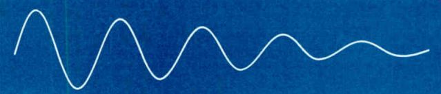
Figure 2. A damped wave
Factors Affecting Resonant Circuits
There are several other things we should know about resonant circuits. For example, we should know the frequency at which oscillation takes place. We should also know how many cycles there will be in a damped wave. We should also know what is meant by the period of a resonant circuit.
Frequency. We already know that resonance occurs when the inductive reactance of the coil is equal to and canceled by the capacitive reactance of the capacitor. Thus, at resonance: XL = Xc We know that the inductive reactance of a coil XL is given by the formula: XL = 6.28 x fxL and the capacitive reactance of a capacitor is given by the formula:
' C C - 6.28 xfxC
Now, since resonance occurs when XL equals Xc, we have:
6.28 x fxL= 6.28 xfxC1 1
This can be manipulated to give us: f2 1 (6.28) 2 x1AxC
Now, if we take the square root of both sides of the equation we get:
f= 1 6.28 x x C
In this formula the times sign is usually omitted so you will usually see it written as:
1 f - 6.28 VI7C
It is a good idea to memorize this formula because it tells you a great deal about the frequency of a resonant circuit. The formula says that the frequency of a resonant circuit varies inversely as the square root of the LC product. When one factor varies inversely with the other, we have a situation where making one bigger makes the other smaller. This means that increasing the size of either L or C will reduce the frequency at which the resonant circuit oscillates, and reducing the size of either L or C will increase the frequency at which the resonant circuit oscillates. We can express this simply by saying: larger L or C, lower frequency; smaller L or C, higher frequency.
In using this formula, the frequency of oscillation will be given in hertz and the value of L and C used must be in henrys and farads, respectively.
When dealing with radio-frequency signals, the inductors used will be measured in micro henrys rather than in henrys and the capacitors in microfarads or picofarads. We can simplify the basic formula for the frequency of a resonant circuit to
f= 159,000\FCC
This formula can be used to find the frequency of a resonant circuit with the inductances given in microhenrys and capacitances in microfarads.
Period. The period of a resonant circuit is the time it takes the resonant circuit to go through one complete oscillation. Thus, if we have a circuit that is resonant at a frequency of 1000 hertz, its period would be 1/1000 of a second.
The period of a resonant circuit is given by the formula: 1 P = where P represents the period of a resonant circuit in seconds, and f is the frequency in hertz.
Since in electronics we are usually dealing with comparatively high frequencies, the period of most resonant circuits will be only a very small fraction of a second. As a matter of fact, the period of many resonant circuits will be only a small fraction of a microsecond.
To simplify things, the microsecond is used in electronics work as the unit of time. The microsecond, abbreviated µsecond or ps, is one millionth of a second. Thus, if a resonant circuit has a period of five millionths of a second, we would say it has a period of 5 microseconds, or 5 µs.
The Q Factor. The number of cycles that will occur when the resonant circuit is shock-excited depends almost entirely upon the Q of the coil. The higher the Q, the more cycles that will occur.
The Q of a coil tells us how good a coil we have. A coil that has a high Q has a high inductive reactance compared to the resistance of the coil. A coil with a low Q has a high resistance compared with the inductive reactance. You will remember that the Q of a coil is expressed by the formula: If we examine this formula and remember that XL varies directly as the frequency and the inductance, we see that Q will vary directly as the frequency and the inductance. You might think that increasing the frequency of a resonant circuit by using a smaller capacitor in combination with a larger coil will result in a higher Q. This will often happen, but the increase in Q is not as great as might be expected because the resistance of the coil is determined by the AC resistance rather than the DC resistance. The AC resistance of a coil actually represent AC losses in the coil, which varies directly as the frequency varies. Increasing the frequency of a resonant circuit increases the inductive reactance of the coil, but at the same time it increases the losses, so that Q normally does not increase as fast as you might expect.
In a resonant circuit with a high-Q coil, there will be a large number of cycles of a damped wave train set up by shock-exciting the resonant circuit. In other words, the amplitude of one cycle will be almost equal to the amplitude of the preceding cycle. But if the Q of the coil is low, the losses in the coil will be high so that the amplitude of each cycle will be substantially less than the amplitude of the preceding cycle. This means that the oscillation will be damped out quite rapidly, and the number of cycles that will occur when the circuit is shock excited will be limited.
In most oscillator circuits, a high-Q coil is used. This means that only a small amount of energy must be supplied to the resonant circuit in order to sustain oscillation. On the other hand, if the coil has a low Q, the losses in the resonant circuit will be high, with the result that a large amount of energy must be supplied to keep the oscillation going.
Summary
When a tank circuit is shock-excited, an oscillation will be built up in the tank circuit. The frequency of the oscillation will depend on the inductance of the coil and the capacity of the capacitor in the circuit. A resonant circuit with a high Q will have almost no losses, so very little energy must be supplied to the circuit to keep the oscillation going. On the other hand, a resonant circuit with a low-Q coil will have high losses so that much more energy is required to keep the oscillation going. A wave train is a series of cycles from an oscillator. A damped wave train is a wave train in which the amplitude of each cycle is less than the amplitude of the preceding cycle. The period of a resonant circuit is the length of time it takes for one full cycle to occur.
Self-Test Questions
1. When a capacitor in a tank circuit is charged, what will cause the current to continue flowing in the tank circuit after the capacitor has discharged?
2. Write the formula for the frequency of a resonant circuit with the inductance in microhenrys and the capacity in microfarads.
3. Write the formula for the period of a resonant circuit.
4. What is a high-Q coil?
LC OSCILLATORS
If a tank circuit such as shown in Fig.1 is shock-excited by momentarily connecting a battery across it, a damped wave such as shown in Fig.2 will be produced. The number of cycles in the wave train will depend upon the Q of the coil. The higher the Q, the more cycles we get.
If, instead of allowing the wave train to damp out as in Fig.2, once each cycle we supply a pulse that is timed to occur at the peak of the oscillation, as shown in Fig.3, we can reinforce the wave train and maintain the oscillation indefinitely.
In an oscillator circuit, this is exactly what we do. We use a transistor to supply a burst of energy at the correct time to make up for losses in the tank circuit so that the oscillation will continue.
In an oscillator circuit some energy is fed from the output back into the input to make up for losses that occur in the circuit. We call the energy fed from the output back to the input feedback, and since it is timed to aid the oscillation, it is called regenerative feedback There are two basic types of feedback used in oscillator circuits: inductive and capacitive. Let's look at inductive feedback first.
Oscillators Using Inductive Feedback
One of the most important and widely used inductive feedback oscillators is the Hartley oscillator. It gets its name from the man who invented the circuit. The original Hartley oscillator circuit was developed for use with a vacuum tube, but an almost identical circuit, which bears the same name, is now used with transistors.
A typical Hartley oscillator is shown in Fig.4.
Notice the oscillator coil L1. The entire coil is wound on a single form with a tap at terminal 2.
Since the turns of the coil are on the same form and close together, the portion of the coil between terminals 1 and 2 is inductively coupled to the portion of the coil between terminals 2 and 3.
Resistor R2 places a positive voltage on the base of Q1 so that, when the oscillator is turned on, current will begin to flow through the transistor and through the part of the coil between terminals 1 and 2. The changing magnetic field produced by the current between terminals 1 and 2 of L1 will set up the field that cuts the turns of the coil between terminals 2 and 3 and induces a voltage in this part of the coil. The voltage will have a polarity such that terminal 3 of the coil is positive with respect to terminal 1. Thus capacitor C1 will be charged so that the plate connected to the R1/C2 junction of the coil will be positive and the other plate negative. The value of C2 is chosen so that its reactance is practically zero at the oscillation frequency; therefore, the base of the transistor is in effect connected directly to C1.
Similarly, the positive voltage on the plate of C1 is in effect applied directly to the base of Q1.
This causes the current through the transistor to increase still further, causing the positive potential of terminal 3 of the coil and on the plate of C1 to increase still more. This in turn makes the base of Q1 still more positive.
While the base of Q1 is positive, some of the electrons crossing the emitter-base junction will leave the transistor at the base and flow into C2, charging it with the polarity shown. As the base is driven further positive, the base current increases until eventually there is a substantial charge on C2.
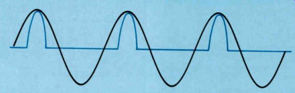
Figure 3. The oscillator pulse is timed to occur at the peak of the oscillation
in the tank circuit to reinforce the oscillation.
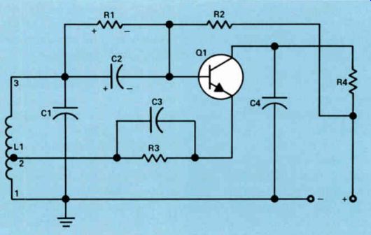
Figure 4. A typical Hartley oscillator.
Eventually a point is reached where the positive voltage on the top plate of C I cannot cause any further increase in the transistor collector current. When this happens, the current flowing through the coil between terminals 1 and 2 will no longer be changing; therefore, there will be no further voltage induced in the coil between terminals 2 and 3. When this happens, the voltage across the coil will begin to decrease and the capacitor C1 will begin to discharge. Now the negative voltage on C2 cuts off the transistor so there is no current flowing through it. C1 continues to discharge until it is completely discharged, but by this time there is a high current flowing in the tank circuit consisting of L1 and C1. This current doesn't drop to zero the instant C1 is discharged, but continues to flow to charge C1 with the opposite polarity. The current will eventually drop to zero, but C1 will be charged and now must discharge. In doing so, it will swing past the point where it is completely discharged and the upper plate will once again start to become positive. Eventually a point is reached where the positive voltage is great enough to overcome the negative voltage across C2. This will cause the transistor to start conducting and once again we get a burst of current through the coil between terminals 1 and 2, which will once again make terminal 3 of the coil still more positive and cause a sharp burst of current through the transistor.
The transistor will conduct in bursts like this once every cycle. The burst of energy, supplied to the tank circuit by the transistor, is timed correctly to overcome the losses in the tank circuit, so the oscillation will continue indefinitely.
When the transistor is not conducting, C2 discharges through R1. This maintains a negative bias across the emitter-base junction. The sole purpose of R2 is to start the oscillator oscillating. When the oscillator is first turned on, R2 places a small positive voltage on the base of the transistor so that there will be a forward bias across the emitter-base junction.
This causes the current to start flowing from ground, through the lower portion of the coil, through R3 to the emitter, and then across the emitter-base junction, where a few electrons leave the base, but the majority flow on to the collector. Once the oscillation starts, this resistor is no longer necessary because the voltage built up across C1 is sufficient to drive the base positive, making the transistor conduct at the correct time during each cycle.
We mentioned earlier that the Hartley oscillator was originally developed for use with vacuum tubes. One of the big differences between a transistor and a vacuum tube is that a transistor is a low-impedance device, whereas a vacuum tube is a high-impedance device. Thus, some times the transistor may load the tank circuit so heavily that the losses become excessively high, and the Q is lowered so that the stability of the oscillator is affected. In some applications, you will find that the base of the transistor is connected to a tap on the oscillator coil as shown in Fig.5. The purpose of connecting the base to the tap is to reduce the loading effect of the transistor on the tuned circuit. The operation of this circuit is essentially the same as the circuit shown in Fig.4.
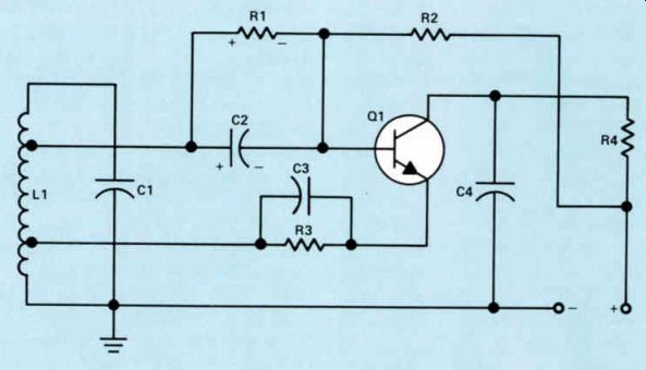
Figure 5. Connecting the base to a tap on the oscillator coil will reduce
the loading effects of the transistor.
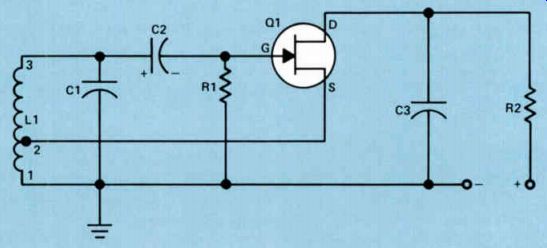
Figure 6. A Hartley oscillator using a junction-type, n-channel field-effect
transistor.
The problem of overloading the resonant circuit can be overcome by the field-effect transistor. A Hartley oscillator using a junction-type, n-channel field-effect transistor is shown in Fig.6.
When the equipment is first turned on, current begins to flow from the negative side of the power supply to terminal 1 of the oscillator coil L1, through the lower part of the coil to terminal 2, and then to the source of the transistor. It will flow through the n-channel to the drain and then through R2 back to the positive side of the power supply.
The current flowing through the lower portion of L1 will induce a voltage in the upper part such that terminal 3 of the coil will be positive with respect to terminal 1. The voltage across L1 will charge C1 so the grounded plate will be negative and the upper plate positive. C2 is a large-capacity capacitor, so it has a low reactance at the oscillator frequency; thus the positive pulse on the upper plate of C1 is fed through C2 to the gate of the transistor. This positive pulse has two effects. It attracts electrons across the gate junction and charges the capacitor C2 with the polarity shown. At the same time, it reduces the resistance of the channel, allowing a higher current to flow through the channel from the source to the drain.
The positive pulse fed to the gate of Q1 will appear for only a short portion of the cycle.
When the positive pulse disappears, the negative voltage on C2 will be applied directly to the gate, and will cut off the flow of current through the channel of the transistor. Meanwhile, C2 will begin discharging through R1 and L1. The time constant of C2 and R1 is long enough so that C2 discharges very little before the next positive pulse comes along and recharges C2, at the same time it allows a burst of current to flow through the transistor. This burst of current supplies sufficient energy to the tank circuit to make up for any losses, and thus oscillation is maintained.
Oscillators Using Capacitive Feedback
There are a number of different oscillator circuits that use capacitive feedback instead of inductive feedback to sustain oscillation. Let's look at some of them now.
The Colpltts Oscillator. The most important of the oscillators using capacitive feedback is the Colpitts oscillator shown in Fig.7. When the equipment is first turned on, current flows through L2, which is a small RF choke used to complete the emitter circuit. R3 is used to place a small positive voltage on the base of the transistor, forward biasing it in order to start it conducting when the equipment is first turned on.
Current flowing through L2 develops a voltage drop across the coil which charges capacitor C2. The charge on the capacitor C2 will start an oscillation in the tank circuit, which consists of L1 and capacitors C1 and C2. Remember that when we have two capacitors connected in series they will act like one capacitor as far as the coil is concerned, and the circuit will start to oscillate. The voltage developed across C1 is the feedback voltage. It is applied between the base and emitter of the transistor.
When the voltage across C1 swings in a positive direction, it makes the end of C1 connected to C3 positive and the other end negative. This will increase the current flow through the transistor, causing an increase in current flow through L2, which charges C2 still further. This in turn causes the current flow through L1 to increase, charging C1 still further and driving the base of the transistor still further positive, building up the oscillation.
At the same time, the positive voltage applied to the base of the transistor through C3 causes base current to flow in the transistor. This charges C3 with the polarity shown. Eventually a point is reached where there is no further increase in current through the transistor.
When this happens, C1 and C2 begin discharging and current begins flowing through L1 in the opposite direction. Meanwhile, the charge built up on C3 places a reverse bias across the emitter-base junction of the transistor so that it stops conducting.
The transistor will be cut off during the remainder of the cycle, and will remain cut off until the next cycle begins. When the voltage on C1 builds sufficiently in a positive direction to overcome the negative voltage across C3, the transistor will start conducting once again.
When this happens, the burst of current through the transistor will build up a voltage across L2, which will recharge C1 and make up for any losses in the circuit.
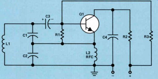
Figure 7. A Colpitts oscillator.
Notice that during the entire half-cycle when the voltage across C1 has a negative polarity so that a negative voltage is fed to the transistor, the transistor will be cut off. Also, during a portion of the other half-cycle, when the voltage on C1 is positive, the transistor will not conduct until the voltage is sufficiently high to overcome the negative bias voltage across C3.
Thus the transistor is conducting for considerably less than one-half cycle. It is operating as a Class C amplifier. Current flows through it only during a small portion of each cycle. However, this burst of current supplies enough energy to the tank circuit to make up for any losses in the tank circuit so that the oscillation will continue.
The amount of feedback voltage supplied to the transistor depends upon the ratio of C1 to C2. If C1 is large compared to C2, the reactance of C1 will be low and the reactance of C2 will be high. Most of the voltage developed across the two capacitors will be developed across the higher reactance, which in this case is C2. This means that the feedback voltage applied to the input of the transistor will be low. However, if C1 is small compared to C2, the reactance of C1 will be high compared to the reactance of C2, and the feedback voltage applied to the input of the circuit will be high.
The ratio of C1 and C2 can be altered to provide the required feedback to the input circuit to sustain oscillation. If the value of C1 is increased and the value of C2 decreased by the correct amount, the total capacitance in the circuit formed as a result of the two capacitors in series remains the same, and hence the resonant frequency of the oscillator does not change.
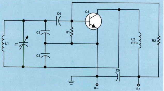
Figure 8. A variation of the Colpitts oscillator.
In some Colpitts oscillators, an additional capacitor is connected directly across L1. This is done to provide some convenient means of changing the resonant frequency so we can vary the frequency at which the oscillator operates. It isn't practical to try to vary both C1 and C2 at the same time and maintain the same voltage division across them. However, a separate capacitor placed across the coil can be varied, which will change the resonant frequency of the oscillator without changing the feed back. This is due to the fact that the values of C1 and C2 remain constant and they will still form a voltage divider. Part of the total voltage developed across the two capacitors in series will be fed back to the input of the circuit.
Again, resistor R3 in the circuit shown in Fig.7 is used to place a small starting bias across the emitter-base junction of Q1 to get the current flow through the transistor started.
Once the oscillation begins, R3 could be re moved from the circuit and the oscillation would continue.
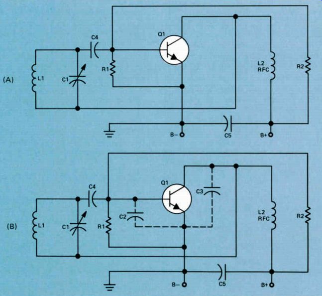
Figure 9. (A) The ultra-audion circuit. (B) The same circuit with internal
transistor capacities added.
There are a number of variations of the Colpitts oscillator circuit. Any time you run into an oscillator where the feedback is controlled by a capacitive voltage divider, such as C1 and C2 in the circuit shown in Fig.7, you can be sure that it is some form of Colpitts oscillator. The Colpitts oscillator can be designed with excel lent frequency stability. By this we mean that once the oscillator is adjusted to operate at a certain frequency, it will not drift from that frequency very much. Some oscillators, on the other hand, do not have good frequency stability and will drift appreciably.
One variation of the Colpitts oscillator is shown in Fig. 8. Here we have capacitor C1 connected across L1, in addition to the voltage divider capacitors C2 and C3. Notice that in the circuit, the collector of the transistor is fed back directly to L1, C1, and C3. The choke coil has been removed from the emitter circuit and the emitter is connected directly to ground.
In the circuit when current begins flowing through the transistor, there will be a voltage developed across the RF choke, L2, and this voltage will charge C3. Once the capacitor is charged, oscillation starts in the circuit just as in the Colpitts oscillator shown in Fig. 7.
The Ultra-Audion Oscillator. A modified form of the Colpitts oscillator that is frequently used in the vhf region is shown in Fig.9. This circuit is called the ultra-audion oscillator.
When the circuit was first developed, it was thought to be a new type of oscillator. However, careful analysis shows that it is really a Colpitts oscillator similar to the one shown in Fig.8.
Figure 9(A) is the schematic diagram of an ultra-audion oscillator and Fig.9(B) shows the ultra-audion oscillator with the transistor capacitances, drawn in dashed lines, that exist between the collector and emitter, and between the base and emitter. We have used the same designations to identify the parts in the circuit shown in Fig.8 and Fig.9(A) so that you can see the similarity between the two circuits. The capacitors represented by the dashed line connections in Fig.9(B) are the internal capacities of the transistor which are not added into the circuit as external parts. However, in the vhf region, these capacitances are large enough to take the place of the actual capacitors used in the low-frequency oscillator shown in Fig.8.
You should learn to recognize this circuit as a form of the Colpitts oscillator because it is widely used at high frequencies. Of course, manufacturers do not draw the internal transistor capacitors on schematic diagrams, so the circuit looks like Fig.9(A) rather than Fig.9(B).
Summary
An oscillator is a circuit used to develop an AC signal. It takes DC from the power supply and changes it into ac.
There are two basic types of LC oscillators, one uses inductive feedback and the other uses capacitive feedback. In both types current flows through the transistor in bursts that last for less than one-half cycle so they are in effect Class C amplifiers. In the Colpitt's oscillator the amount of feedback can be varied by varying the size of the voltage divider capacitors across the tank coil.
Both types are self regulating: the energy supplied to the tank circuit makes up for losses in the tank circuit.
The ultra-audion oscillator is a modified Colpitts oscillator. In this circuit, the external voltage-divider capacitors connected across the coil are omitted. These are not needed because in the vhf region where the circuit is used the capacity between the collector and emitter takes the place of one capacitor and the capacity between the base and the emitter of the transistor replaces the other capacitor.
Self-Test Questions
5. What do we mean when we refer to an oscillator as a "self-regulating oscillator?"
6. What two types of feedback are used in LC oscillators?
7. What type of feedback is used in the Hartley oscillator?
8. What type of feedback is used in the Colpitts oscillator?
9. What type of oscillator is the ultra audion oscillator?
-----------------------
CRYSTAL OSCILLATORS
The oscillator in a radio or TV broadcast station, the color oscillator in a TV receiver, various oscillators in video cassette recorders, and other oscillators in critical applications must be held to a very close frequency tolerance. LC oscillators can be designed with very good frequency stability but their frequency stability is not good enough for many applications. Usually, crystal oscillators are used in applications where the frequency must be held to a very close tolerance. In this section of the lesson, you will study crystal oscillator circuits and learn how they work.
The Piezoelectric Effect
The operation of a crystal oscillator depends on a peculiar effect shown by quartz crystals that is known as the piezoelectric effect. Because of this effect, a crystal that has been suitably cut from a piece of quartz and placed in a suitable holder can be substituted in place of an LC resonant circuit. Now let's see what the piezoelectric effect is and how the crystal oscillator works.
In its natural state, a quartz crystal has a hexagonal cross section and pointed ends like the one shown in Fig.10. An imaginary line drawn between the two apexes is called the Z axis. The axis is shown in Fig.10. There are two other sets of axes labeled the X axis and the Y axis. Notice that there are three X axes and three Y axes. Both the X axes and the Y axes are perpendicular to the Z axis. The X axes pass through the corner of the crystal, whereas the Y axes are perpendicular to the face of the crystal.
Small pieces of crystal, usually about 1/2 " square and of varying thicknesses, can be cut from a natural quartz crystal. If the crystal is cut perpendicular to the Y axis, it is called a Y -cut crystal, and if it is cut perpendicular to the X axis, it is called an X-cut crystal. These are shown shaded in Fig.10.
X-cut crystals have been widely used in crystal oscillators, but other cuts are also used. Two of these are the AT cut and the BT cut, both of which are cut perpendicular to the Y axis, but at an angle to the Z axis.
It is the peculiar property of a crystal that if an electric stress is applied in the direction of the X axis, a mechanical stress is produced in the direction of the Y axis, and if a mechanical stress is placed along the Y axis, it will cause an electrical stress on the X axis. The electrical stress produced by mechanical force is termed the piezoelectric effect.
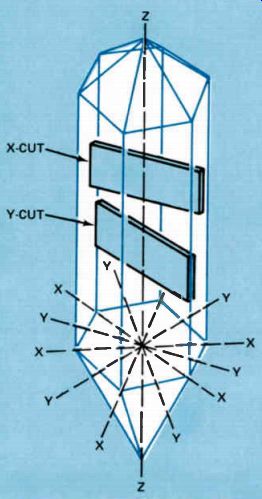
Figure 10. Major axes in a quartz crystal.
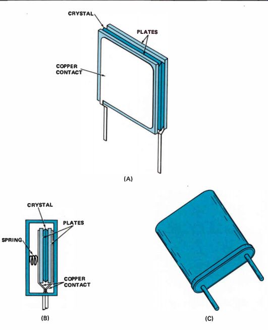
Figure 11. A crystal and its holder.
For use in crystal oscillators, crystals are cut into small squares of varying thicknesses. The crystal is then mounted between two metal plates which will make contact with the two large surfaces of the crystal. The plates are usually held in contact at the surface by springs. The entire assembly is put in a container and hermetically sealed to prevent changes in humidity from affecting the frequency of the crystal. A drawing of the crystal is shown in Fig.11(A), and the side view of the crystal is shown in Fig.11(B). The complete crystal inside of the hermetically sealed holder is shown in Fig.11(C). When an AC voltage is applied between the plates and across the quartz crystal, the crystal can be made to vibrate. When a crystal is ground to the proper thickness so that mechanical resonance exists at the frequency of the AC voltage, the amplitude of the vibrations will be quite large.
The equivalent electrical circuit of the crystal is shown in Fig.12. C1 represents the capacitance formed by the plates. The crystal itself is represented by L1, C2, and R 1. The crystal may be operated as either a series- or a parallel resonant circuit. When operated as a series resonant circuit, the resonant frequency of the circuit is then determined only by L1 and C2.
The impedance of the crystal will be lowest at the series-resonant frequency. When operated as a parallel-resonant circuit, the combination of L1 and C2 has the net effect of an inductance because the inductive reactance of L1 is much larger than the capacitive reactance of C2. The resonant frequency of a parallel circuit is determined by C1 and the net inductance of the series combination of L1 and C2. The impedance of the crystal is highest at the parallel resonant frequency. In a parallel-resonant configuration, the resonant frequency of the circuit is determined by both the crystal and the externally connected circuit components. Crystals are manufactured for use either as a series resonant or a parallel-resonant circuit. A crystal that has been manufactured for a series-resonant application normally cannot be used in parallel-resonant applications.
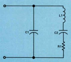
Figure 12. The equivalent electrical circuit of a crystal and its holder.
Simple Crystal Oscillators
To help see how a crystal oscillator works, look at the LC oscillator shown in Fig.13. This oscillator is called a tuned-base, tuned-collector oscillator. It is easy to see where it gets its name, since there are resonant circuits in both the base and the collector circuits.
The oscillator works because of the transistor's collector-base capacitance between the output circuit and the input circuit. When a resonant circuit in the output is tuned to a frequency slightly lower than the operating frequency, it will act like an inductance. Under these conditions, the phase of the signal that is fed from the output back to the input is correct to aid the voltage in the input tank circuit consisting of L1 and C1, and thus oscillation occurs.
The crystal oscillator shown in Fig.14 is a simple modification of the oscillator shown in Fig.13. Here the crystal has been substituted for the resonant circuit in the input circuit of the oscillator. The crystal acting as a parallel-resonant circuit is the equivalent of the circuit that has been removed. Therefore, the crystal oscillator operates in exactly the same way as the oscillator shown in Fig.13. The crystal oscillator has the advantage of excellent stability over the LC oscillator. The stability of the oscillator can be further improved by keeping the tempera ture of the crystal constant at all times. In broadcast transmitters, the crystal is placed inside an oven that is kept at a constant temperature.
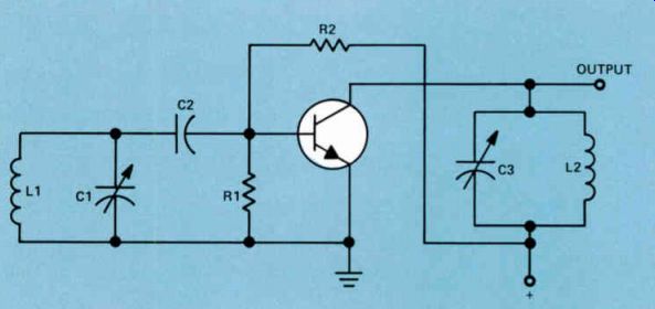
Figure 13. A tuned-base, tuned-collector oscillator.
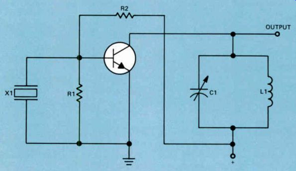
Figure 14. A simple crystal oscillator.
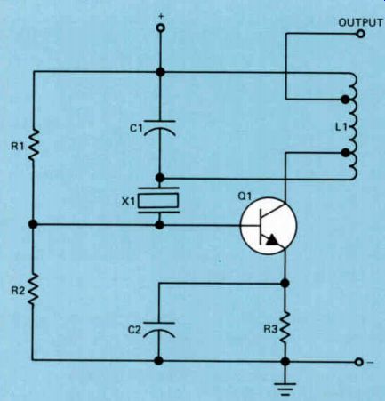
Figure 15. Transistor crystal-controlled oscillator using a series-resonant
crystal.
Another example of a crystal oscillator is shown in Fig.15. In this application, the crystal is used as a series-resonant circuit; it is in the path between the collector circuit of the transistor and the base. The crystal provides a low impedance at the resonant frequency so that energy at this frequency is readily fed through the crystal from the collector and back to the base. At frequencies above and below the frequency of the crystal, the impedance of the crystal increases so that energy cannot be fed back at these frequencies. Thus the crystal basically controls the frequency at which the oscillator operates. You will find crystal oscillators used in both parallel applications, as shown in Fig. 14, and series applications, as shown in Fig.15.
Problems in Servicing Crystal Oscillator
Crystal oscillators present some special servicing problems. Sometimes the crystal simply won't oscillate. Most of the crystals you are likely to encounter will be hermetically sealed units; and if the crystal fails to oscillate, there is nothing you can do but replace it, providing everything in the circuit checks satisfactorily. If the crystal is the type that can be dismantled, sometimes you can dismantle it and inspect the crystal to find the trouble. You may find that there is a corner chipped or the crystal has been cracked. In either case the crystal should be replaced.
But often there is no apparent defect. This is one of the peculiarities of crystals; sometimes they simply fail to oscillate. Usually when you encounter this, the only thing you can do is replace the crystal.
Sometimes the operation of the crystal be comes erratic. When the power is applied to the oscillator, it may start oscillating one time and another time it will not oscillate. This may be due to dirt in the crystal or to a cracked crystal.
Again, in the case of a hermetically sealed unit, which is the type you will encounter most frequently, there is nothing you can do with the unit but replace it.
Another problem often encountered with crystals is that the frequency at which they oscillate becomes erratic. You may turn on the crystal-controlled oscillator and find that it is operating at some frequency other than the frequency for which it has been ground. The next time you turn on the equipment, it might oscillate at the correct frequency. When you encounter this problem in the crystal, the only thing you can do is discard it.
Summary
Crystal oscillators are used in applications where better frequency stability is needed than can be obtained with an LC oscillator. The frequency of crystal oscillators is controlled by a quartz crystal that has been cut to the thickness that provides the required operating frequency. There are three major axes of a quartz crystal: the Z axis, the X axis, and the Y axis. An effect known as the piezoelectric effect makes the use of crystals possible in a resonant circuit. This is the electrical stress produced in the crystal along one axis when a mechanical stress is placed along another axis.
Crystals can be used both as parallel, resonant circuits or as series-resonant circuits. Crystals made for use in parallel resonant circuits have a high impedance, whereas crystals used in series-resonant applications have a low impedance. Usually a crystal cut for one mode of operation cannot be used in the other.
Self-Test Questions
10. What are the three major axes of a quartz crystal?
11. What is the piezoelectric effect?
12. What two types of circuits may a crystal form?
13. What is the chief advantage of a crystal oscillator over an LC oscillator?
14. If a hermetically sealed crystal starts oscillating sometimes when the equipment is turned on, but fails to oscillate at other times, how is the problem remedied?
---------------------
RC COUPLED OSCILLATORS
The oscillators that we have studied so far have been LC oscillators. Now we will study RC oscillators, so called because they use resistance and capacitance.
The most common RC oscillator is the multivibrator. It is a two-stage oscillator.
During the first half-cycle, one stage is turned full on - it is passing maximum current. The other stage is cut off. During the other half cycle, the status of the two stages reverses. The stage that was cut off goes into maximum conduction and the stage that was conducting during the first half-cycle is now cut off.
You have already studied the multivibrator known as a flip-flop. The flip-flop is a bistable multivibrator. Bistable means it has two stable states. It rests in one of the states until it receives a trigger pulse. When triggered, the flip-flop changes state and remains in the new condition until triggered again.
Another type of multivibrator is the monostable multivibrator. This multivibrator has one stable state. When it receives a trigger pulse, it generates a single output pulse. One output pulse is produced for each trigger pulse. Upon receiving a trigger input, it switches to the semi stable state for a fixed period of time and then returns to its stable condition to wait for another trigger pulse.
A third type of multivibrator is the astable, or free-running, multivibrator. This type of multivibrator is also an oscillator; once it starts running, it continues to run. In this section of the lesson, we are going to deal with the free running multivibrator.
A Collector-Coupled Multivibrator
A schematic diagram of a collector-coupled multivibrator is shown in Fig.16. The multivibrator gets its name from the fact that the output signal from Q1 is coupled from the collector through C1 to the base of Q2, and the output from Q2 is coupled from the collector to the base of Q1 through C2.
In the circuit shown in Fig.16, one of the transistors will start conducting first or slightly faster than the other. Let's assume that Q1 starts conducting first. As the current through Q1 increases, the voltage drop across R1 will increase. This will cause the voltage at the collector of Q1 to swing in a negative direction.
Electrons will flow through the transistor Q1 to the one plate of C1, charging it with the polarity shown. At the same time, electrons leave the positive plate and flow through R3 back to B+. In flowing through R3 they set up a voltage drop across the resistor having a polarity such that the base end is negative. The negative voltage across R3 drives the base of the transistor Q2 negative with respect to the emitter of Q2 so Q2 will be cut off. The transistor will be cut off as long as C1 is charging through R3. It will be developing a voltage across R3 great enough to overcome the for ward bias that the power supply is applying through R3 to the base of the transistor.
Eventually C1 will be charged and the current flow from it through R3 will stop. Now the power supply voltage is fed through R3 to the base of Q2, turning this transistor on. When this happens, current will begin to flow through Q2 and R4, causing the voltage on the collector of Q2 to drop. Now C2 will charge with the polarity shown, causing electrons to leave the positive plate of C2 and flow through R2. This will develop a voltage drop across this resistor having a polarity such that the base end is negative. This will completely cut off Q1. Once Q1 is cut off, there will be no current flow through R1 and no voltage drop across it.
Meanwhile, the positive plate of C1 is connected to the base of Q2. With Q2 conducting, the resistance between the emitter and base is low so that C1, which is charged with the polarity shown, is connected directly from B- to B+. The capacitor must discharge and charge with the opposite polarity. Electrons will flow from B- to the emitter of Q2 across the emitter-base junction, out of the base, into the plate of C1 marked with a + sign and out of the plate marked with a - sign through R1 to B+. Since practically all of the electrons flowing to the base of Q2 are being used to charge C1, there will be little or no voltage drop across R3. Thus the potential on the base of Q2 will attempt to swing highly positive, driving this transistor into saturation. The transistor re mains in this condition until C2 is completely charged, at which time Q1 will begin conducting again.
When this happens, the voltage at the collector of Q1 drops, and C1 begins discharging and charging with the polarity shown. To do this, electrons will flow out of the positive plate of C1 through R3, developing a potential such that the base end of R3 is negative. This will cut off Q2 and cause the collector voltage to rise to the B+ value. Now C2 must discharge and charge with the opposite polarity; in doing so, it will tend to pull the base of Q1 highly positive, causing Q1 to saturate almost instantly. This action of first one transistor conducting and then the other, will go on indefinitely. Thus the multivibrator is free-running.
Transistors are particularly well-suited for this type of application because they can be switched from saturation, or maximum current condition, to cutoff very rapidly. In many applications, this rapid change from one state to the other is desirable.
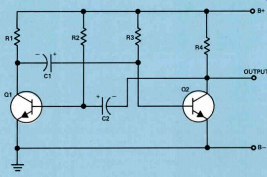
Figure 16. A collector-coupled multivibrator.
An Emitter-Coupled Multivibrator
Another widely used multivibrator is the emitter-coupled multivibrator. A schematic diagram of this type of multivibrator is shown in Fig.17. The operation of this multivibrator is somewhat different from the operation of the collector-coupled multivibrator.
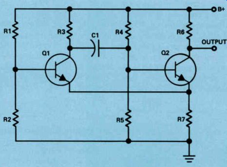
Figure 17.
Resistors R1 and R2 place a forward bias across the emitter-base junction of Q1 and resistors R4 and R5 place a forward bias across the emitter-base junction of Q2. When the equipment is first turned on and both transistors start to conduct, the capacitor C1 must charge. To charge the capacitor, electrons will flow from ground through R5, R7, and the emitter-base circuit of Q2, into one plate of C1 and out of the other, and then through R3 to B+. The electrons flowing through R5 set up a voltage drop across this resistor having a polarity such that the base end of the resistor is positive. This causes Q2 to conduct heavily and develop a voltage drop across R7 such that the emitter end is positive. This positive voltage will overcome the forward bias on Q1 and cut Q1 off. Once this happens, there will be no current flow through R3 from Q1 so that C1 must charge to almost the full supply voltage.
This causes additional electrons to flow through R5 in parallel with R7 and the emitter-base circuit Q2. Q2 goes into saturation, creating a high positive voltage across R7.
As long as C1 is charging, Q2 will be conducting heavily. But as soon as C1 is charged, the bias across the emitter-base junction of Q2 will drop, causing the current flow through the transistor to drop. When this happens, the voltage across R7 will drop and Q1 will begin to conduct. Once Q1 starts to conduct, there will be a voltage drop across R3, and C1 must discharge. When C1 discharges, electrons will flow through R4, developing a voltage across this resistor with a polarity such that the base end is negative. This will cut off Q2 so that current flow through R7 from Q2 will drop to zero. When this happens, the forward bias across the emitter-base junction of Q1 will increase, causing it to conduct more heavily.
The voltage drop across R3 will increase, causing C1 to discharge further. Eventually a point is reached where C1 is discharged, the negative voltage on the base of Q2 due to the voltage drop on R4 will disappear and Q2 will start across R7 which will cut off Q1, and C I will once again charge through R5 and R3, driving Q2 into saturation. This oscillation of first Q1 and then Q2 conducting will continue indefinitely.

Figure 18. Output from a symmetrical multivibrator.
Multivibrator Output Signals
Multivibrators are called symmetrical multi vibrators when each transistor conducts for the same length of time. In the circuit shown in Fig.16, this is what happens if C1 is equal to C2 and R2 is equal to R3. Under these conditions, Q1 will conduct for a certain period of time and then be cut off. Q2 will conduct for an equal period of time while Q1 is cut off. Under these circumstances, the output from the multivibrator will resemble a waveform shown in Fig.18.
In the circuit shown in Fig.16, C2 discharging through R2 keeps Q1 cut off for a certain period. Similarly, C1 discharging through R3 keeps Q2 cut off. As long as the time constant of C2 and R2 is equal to the time constant of C1 and R3, the output from the multivibrator will be symmetrical. However, by changing the time constants of these two networks we can obtain an asymmetrical output as shown in Fig.19. In the circuit shown in Fig.16, if Q2 conducts longer than Q1, we'll have an output like the one shown in Fig.19(A). On the other hand, if Q1 conducts longer than Q2, we can get an output as shown in Fig.19(B).
The value of the RC network used in coupling the transistors in Fig.16 will not only determine the waveshape of the output of the circuit; it will also affect the frequency at which the oscillator operates. For example, if the time constant of C1 and R3 or the time constant of C2 and R2 is decreased, the frequency at which the oscillator operates will increase. Similarly, if the time constant of the network is increased, the frequency at which the oscillator will operate is decreased. This type of multivibrator can be made to operate over a wide range of frequencies by selecting the time constant of the RC coupled networks.
In the multivibrator shown in Fig.17, Q2 conducts when C1 is charging and Q1 conducts when it is discharging. The charging path for C1 is through R5 in parallel with R7 and the emitter-base junction of Q2 and R3. The resistance of R5 in parallel with R7 and the emitter base junction of Q2 is so low when compared to the resistance of R3 that it can be ignored.
Therefore, the time constant of the charging network is primarily the time constant of C1 and R3.
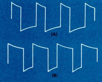
Figure 19. Output from an asymmetrical multivibrator with (A) having
a shorter pulse width than (B).
C1 discharges through R7, Q1, and R4. The resistance of R7 in series with Q1 is so low when compared to the resistance of R4, they can be ignored. Therefore the discharge time is primarily the time constant of C1 and R4. Thus, if we make R3 equal to R4, the output from the multivibrator will be symmetrical. But in most cases R4 is much larger than R3.
This means that the discharge time of C1 will be much longer than the charge time. Therefore, Q2 will be cut off for a period greater than the time it is conducting, and the output will be like Fig.19(B). Again, the time constant of C1 and R3 and the time constant of C1 and R4 determine the frequency at which the multivibrator operates.
To increase the frequency of the multivibrator operation, we can decrease the value of C1. To decrease the multivibrator frequency, we can increase the capacity of C1.
Summary. The most common RC oscillator is the multivibrator. There are three types of multivibrators. The monostable multivibrator has one stable state. The bistable multivibrator, often called a flip-flop, has two stable states. The astable multivibrator is a free-running multivibrator.
There are two basic types of astable multivibrators, the collector-coupled multivibrator and the emitter-coupled multivibrator. The shape of the output signal and the frequency at which the multivibrator operates can be controlled by controlling the RC time constant of the coupling net works.
Self-Test Questions
15 Which components primarily deter mine the frequency at which the multivibrator shown in Fig.16 operates?
16 If C1 equals C2 and R2 equals R3 in the circuit shown in Fig.16, will the output from the multivibrator be sym metrical or asymmetrical?
17 In the circuit shown in Fig.16, if the value of C2 and R2 is decreased, how will the frequency of the multivibrator be affected?
18 In the circuit shown in Fig.17, if R3 is equal to R4, will the output be sym metrical or asymmetrical?
19 What is a bistable multivibrator?
20 What is a monostable multivibrator?
ANSWERS TO SELF-TEST QUESTIONS
1 The inductance of the coil causes the current to continue flowing after the capacitor has discharged. Inductance is the quality of a coil that opposes any change in the current flowing through it.
1 59' 000
2 f = 1
3 P = - f
4 A high-Q coil is a coil in which the ratio of the inductive reactance of the coil to the resistance of the coil is high.
5 When we say that an oscillator is self regulating, we mean that the energy supplied to the tank circuit is just what is needed to make up for losses in the tank circuit.
6 Inductive feedback and capacitive feedback.
7 The Hartley oscillator uses inductive feedback.
8 The Colpitts oscillator uses capacitive feedback.
9 The ultra-audion is a form of the Colpitts oscillator that is used at very high frequencies.
10 The three major axes of a quartz crystal are the X axis, the Y axis, and the Z axis.
11 The piezoelectric effect is the peculiar property of a crystal whereby, if an electrical stress is applied in the direction of the X axis, a mechanical stress will be produced in the direction of the Y axis. If a mechanical stress is placed along the Y axis, it will cause an electrical stress on the X axis.
12 Crystals may be used in series resonant or parallel-resonant circuits.
13 The chief advantage of a crystal oscillator over an LC oscillator is excellent frequency stability.
14 When the performance of the crystal is erratic, the only solution is to re place the crystal.
15 The frequency at which the oscillator shown in Fig.16 operates is deter mined by C2-R2 and C1-R3.
16 The output will be symmetrical.
17 The frequency of the multivibrator will increase.
18 The output will be symmetrical.
19 A bistable multivibrator is a multivibrator with two stable states. A flip flop is a bistable multivibrator.
20 A monostable multivibrator is a multivibrator with only one stable state.
A pulse may cause it to change to the unstable state, but it will return to the stable state, and remain there until another pulse occurs.
LESSON QUESTIONS
This is Lesson Number 2231.
Make sure you print your name, student number, and les son number in the space provided on the Lesson Answer Form. Be sure to fill in the circles beneath your student number and lesson number.
Reminder: A properly completed Lesson Answer Form allows us to evaluate your answers and speed the results and additional study material to you as soon as possible. Do not hold your Lesson Answer Forms to send several at one time. You may run out of study material if you do not send your answers for evaluation promptly.
1. A damped wave is a wave that:
a. Describes a wet oscillator coil.
b. Increases in frequency.
c. Decreases in frequency.
d. Decreases in amplitude.
2. The period of a circuit that is resonant at a frequency of 1 MHz is:
a. 1000 microseconds.
b. 100 microseconds.
c. 10 microseconds.
d. 1 microsecond.
3. If the capacity in an LC circuit is increased, the resonant frequency of the circuit will:
a. Remain the same.
b. Increase.
c. Decrease.
d. Become unstable.
4. If the capacity in an LC circuit is cut in half and the inductance is doubled, the resonant frequency will:
a. Remain the same.
b. Increase.
c. Decrease.
d. Become unstable.
5. In the oscillator shown in Fig.4, transistor Q1 is conducting:
a. All the time.
b. For more than half a cycle.
c. For one-half cycle.
d. For less than half a cycle.
6. In the oscillator circuit shown in Fig.7, after the oscillator has started operating, R3 is removed from the circuit. When this hap pens, the oscillator will:
a. Stop oscillating.
b. Continue oscillating.
c. Increase in frequency.
d. Decrease in frequency.
7. The ultra-audion oscillator is a form of the:
a. RC-coupled oscillator.
b. Colpitts oscillator.
c. Hartley oscillator.
d. None of the above.
8. A crystal in a crystal oscillator may act as: A parallel-resonant circuit.
A series-resonant circuit.
Either a series-resonant or a parallel resonant circuit.
d. None of the above.
a.
b.
c.
9. An astable multivibrator is a multivibrator that:
a. Has one stable state.
b. Has two stable states.
c. Is free-running.
d. Is none of the above.
10. In the circuit in Fig.16, which part affects the frequency of the multivibrator?
a Q1.
b. Q2.
c. R1.
d. C1.
---------------------
BELIEVE IN YOURSELF
Here are a some statements made by famous, successful people on the subject of believing in yourself. I quote them just to show you how important self-confidence really is: "Anything that you have a real desire to do, you have the capacity to do. Believe that and act upon your belief. There are no dreams that can't come true." "Believe in yourself. Believe in humanity. Believe in the success of your undertakings. Fear nothing and no one. This way, you cannot fail."
"I CAN IF I THINK I CAN! Write these words in letters an inch high and put them where you can see them every day. Memorize and repeat them -- aloud and to yourself--a dozen times a day."
| Top of Page | PREV | NEXT | Article Index |