AMAZON multi-meters discounts AMAZON oscilloscope discounts
--------------
Analog Electronics
Table of Contents
Overview
Experiment 1: Transformer Operation
Experiment 2: Rectifier Operation
Experiment 3: Filter Operation
Experiment 4: Increasing Circuit Voltage
Experiment 5: Shunt Regulation with a Zener Diode
Experiment 6: IC Series Regulator
Experiment 7: NPN Transistor Voltage Amplifier
Experiment 8: IC Operational Amplifier
Experiment 9: NPN Transistor Multivibrator
Experiment 10: IC Function Generator
Examination Questions
---------------
Objectives
In this training manual, you will use your Digital Multi meter to...
• Connect and test a power transformer secondary circuit.
• Construct and test a full-wave bridge rectifier.
• Add a ripple filter and observe its action.
• Construct and test a shunt Zener regulator.
• Construct and test an IC series regulator.
• Construct and test a common-emitter amplifier.
• Construct and test a two-stage IC amplifier.
----------------
Overview
In this training manual, you will put your knowledge of analog electronics to work. You will construct several circuits on your Discovery Lab and verify their operation. By identifying, handling, connecting, and testing real electronic components, you will make circuit theory come to life.
In each of the following sections, you will be instructed to wire a circuit, using both schematic and pictorial diagrams. After you finish connecting each circuit, you will apply power and make some measurements with your digital multimeter. You will deduce from these measurements how the circuit performs.
At the end of this training manual, is an examination consisting of 10 multiple choice questions. Each of the questions pertains to one of the following experiments. The questions are in the same order as the experiments. There are four questions about basic power supplies and two questions each about voltage regulators, amplifiers, and oscillators.
As you perform each of the experiments, you will be instructed to turn to the examination and answer the relevant question. When you are finished with all 10 questions, follow the instructions at the beginning of the examination to fill in your answer card for this training unit.
Experiment 1: Transformer Operation Introduction
Almost all electronic circuits and equipment need to operate from a low voltage de source. Electrical power is distributed in the form of a relatively high AC voltage, so a power supply section or module is used to change the voltage level and convert from AC to dc. In this section, you will construct and test a power supply similar to that used in most modern electronic equipment.
If you were constructing a complete power supply, one of the first things you would do would be to arrange the wiring between the power transformer's primary winding and the AC power line. Your Discovery Lab already has the primary connections in place, both for convenience and to prevent you from having to deal with the dangerous AC power line.
Materials Needed
For this experiment, you'll need your Discovery Lab, Digital Multimeter, and a length of hook-up wire.
Procedure
Using your Discovery Lab as a base, connect the center-tapped transformer secondary leads to the breadboard strip as shown in Figure 1-1.
Step 1. For your personal safety and that of the equipment, unplug the Discovery Lab's power cord before you make these connections.
Step 2. Prepare three 6" lengths of solid hook-up wire by removing 1 / 4" of insulation from each end of each wire.
Step 3. Connect the leftmost terminal of the power transformer secondary (marked 15VAC) to point C on the breadboard strip, as shown in Figure 1-1.
When you insert the wire ends into the breadboard strip's holes, stop Just short of full insertion so that enough bare wire is exposed for your meter lead to make good contact.
Step 4. Connect the center terminal of the power transformer secondary (marked with a ground symbol) to point B on the breadboard strip.
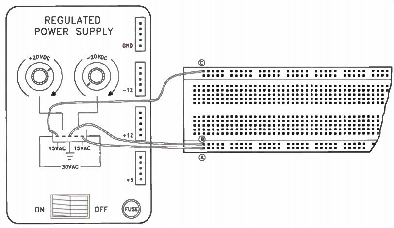
Figure 1-1. Connecting the power transformer secondary leads.
Step 5. Connect the rightmost terminal of the power transformer secondary (marked 15VAC) to point A on the breadboard strip.
Step 6. Check your wiring to make sure it is correct and then apply power and turn on the Discovery Lab's power switch.
Step 7. Set your digital multimeter to measure about 50 Vac and measure the transformer's output voltages. Use point B as a common point; you should find about 15 volts AC at either point A or point C. Now shift the common lead to point A and measure the voltage at point C. Use this measurement to answer Examination Question 1.
Step 8. After you take your measurements, remove the wire connecting point C to the transformer secondary.
Results:
You verified the operation of the power transformer; you found that half of the secondary winding can be used to provide one voltage, or the entire winding can be used to provide twice as much voltage to circuits that need that much.
-------------
Experiment 2: Rectifier Operation
Introduction:
Now you will add a full-wave bridge rectifier to the power transformer. This will convert the AC voltage from the transformer into DC voltage.
Materials Needed:
For this experiment, you'll need your Discovery Lab with the wiring in place from the previous experiment, your digital multimeter, four IN4002 diodes, and one 10k resistor.
Procedure Add a full-wave bridge rectifier to the power transformer as Figure 2-1 shows in schematic form. All rectifier diodes are 1N4002 or equivalent and are rated at 1 amp (A), 100 volts (V) ply. Place the components as shown pictorially in Figure 2-2.
Step 1. For your personal safety and that of the equipment, again unplug the Discovery Lab's power cord before you make these connections.
Step 2. Connect a rectifier diode as D1 from point A to point -. Step 3. Connect a rectifier diode as D2 from point B to point -. Step 4. Connect a rectifier diode as D3 from point B to point +. Step 5. Connect a rectifier diode as D4 from point A to point +. Step 6. Connect a 10k (brown-black orange) resistor as the load ( RL) from point - to point +. Step 7. Check your wiring to make sure it is correct and then apply power and turn on the Discovery Lab's power switch.
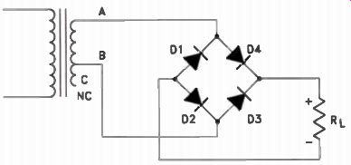
Figure 2-1. Schematic of the full-wave bridge rectifier.
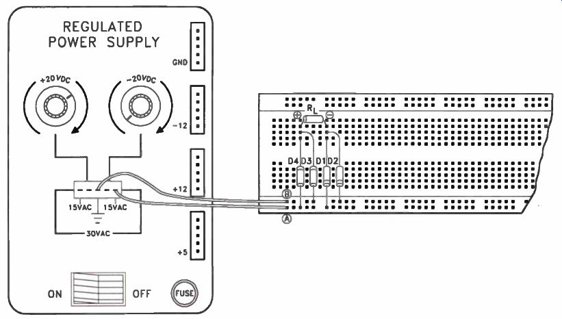
Figure 2-2. Wiring the full-wave bridge rectifier.
• Step 8. Set your digital multimeter to its 50-V scale and measure the DC voltage at the rectifier's output. Connect the digital multimeter's minus (-) jack to point - as a common point. Record your reading in the upper-left space of Figure 2-3.
Step 9. Set your digital multimeter to measure about 50 Vac and measure the AC ripple voltage at the rectifier's output. Connect the digital multimeter's minus (-) jack to point - as a common point. Record your reading in the upper-right space of Figure 2-3. Use these measurements to answer Examination Question 2.
Results:
You constructed a full-wave bridge rectifier circuit and observed its operation without any ripple filter. You should have observed that, while de output voltage is present, there is also a large AC component at the output.
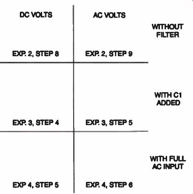
Figure 2-3. For the full-wave bridge rectifier experiment, enter your
measured values in this voltage chart.
--------------
Experiment 3: Filter Operation
Introduction:
Now you will add a filter capacitor to the power supply circuit. This will smooth the ripple from the pulsating DC voltage and produce one more pure DC output voltage.
Materials Needed:
For this experiment, you'll need your Discovery Lab with the wiring in place from the previous experiment, your digital multimeter, and one 100-microfarad (e), 50-V electrolytic capacitor.
Procedure:
Now add a 100-pF, 50-V electrolytic capacitor to the circuit as Figure 3-1 shows in schematic form. Orient the capacitor as shown pictorially in Figure 3-2.
Step 1. For your personal safety and that of the equipment, again unplug the Discovery Lab's power cord before you make these connections.
Step 2. Connect the filter capacitor from point - to point +. Note that the + end of the capacitor must be on point +, and vice versa.
Electrolytic capacitors like this are polarity sensitive and will not work if connected back wards! Step 3. Check your wiring to make sure it is correct and then apply power and turn on the Discovery Lab's power switch.
Step 4. Set your digital multimeter to measure about 50 V and measure the DC voltage at the rectifier's output. Connect the digital multimeter's minus (-) jack to point - as a common point. Record your reading in the center-left corner of Figure 2-3.
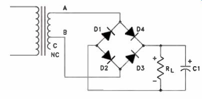
Figure 3-1. How a filter capacitor is added to the circuit.
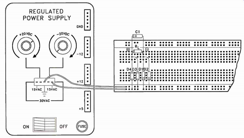
Figure 3-2. While connecting the filter capacitor, observe polarity.
Step 5. Set your digital multimeter to measure a low AC voltage and measure the AC ripple voltage at the rectifier's output. Connect the digital multimeter's minus (-) jack to point - as a common point. Record your reading in the center-right corner of Figure 2-3. Use these readings to answer Examination Question 3.
Results:
You added a filter capacitor at the output of the full-wave bridge rectifier circuit and observed its effect on DC and AC output voltage.
You should have noticed a dramatic decrease in the AC ripple voltage when you installed the filter capacitor.
----------------------
Experiment 4: Increasing Circuit Voltage
Introduction:
Now you will increase the AC voltage applied to the rectifier circuit by using the entire transformer secondary winding rather than just half of the winding, as before.
Materials Needed:
For this experiment, you'll need your Discovery Lab with the wiring in place from the previous experiment and your digital multimeter.
Procedure:
Now connect the power transformer to the rectifier circuit to use the entire secondary winding instead of only half.
Step 1. For your personal safety and that of the equipment, again unplug the Discovery Lab's power cord before you make these connections.
Step 2. Disconnect the wire connecting point B with the Discovery Lab's center power transformer terminal.
Step 3. Connect point B instead to the left most transformer terminal (marked 15VAC). Step 4. Check your wiring to make sure it is correct and then apply power and turn on the Discovery Lab's power switch.
Step 5. Set your digital multimeter to measure about 50 V and measure the de voltage at the rectifier's output. Connect the digital multimeter's minus (-) jack to point - as a common point. Keep your fingers away from the circuit conductors to avoid getting a shock. Record your reading in the bottom left corner of Figure 2-3.
Step 6. Set your digital multimeter to measure a low AC voltage and measure the AC ripple voltage at the rectifier's output. Connect the digital multimeter's minus (-) jack to point - as a common point. Again, keep your fingers away from the circuit conductors to avoid get ting a shock. Record your reading in the bottom right corner of Figure 2-3. Use these readings to answer Examination Question 4.
• Step 7. If you are finished with the power supply experiments, unplug the Discovery Lab's AC power cord and remove the wires and components you added for these experiments. Save them for later use in other experiments.
Results In this experiment, you doubled the amount of AC voltage applied to the input of the full wave bridge rectifier circuit. You should have observed that the DC output voltage was doubled as a result.
---------------
Experiment 5: Shunt Regulation with a Zener Diode Introduction
In this experiment, you will use one of your Discovery Lab's variable de outputs to demonstrate the operation of a simple shunt Zener diode voltage regulator.
Materials Needed:
For this experiment, you'll need your Discovery Lab, your digital multimeter, one 100-ohm (Ω), 1-W (W) resistor, two 1-k resistors, one 6-V, 1 / 2 -watt (W) Zener diode, and a length of hook-up wire.
Procedure:
Using your Discovery Lab as a base, con struct the circuit that is shown in schematic form in Figure 5-1. Wire the components as shown in Figure 5-2: Step 1. For your personal safety and that of the equipment, unplug the Discovery Lab's power cord before you make these connections.
Step 2. Prepare two 6" lengths of solid hook-up wire by removing 1/4 " of insulation from each end of each wire.
Step 3. With one of the wires, connect the Discovery Lab's +20-V output to point A on the breadboard strip.
Step 4. Use the other wire to connect the Discovery Lab's ground to point B on the breadboard strip.
Step 5. Connect a 100 ohm, 1-W resistor (R1) from point A to point C on the breadboard strip.
Step 6. Connect a 6-V, 1/2-W Zener diode from point C to point B on the breadboard strip. Make sure that the Zener's cathode (striped end) is connected to point C.
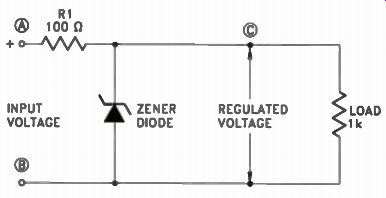
Figure 5-1. The Zener diode shunt regulator circuit.
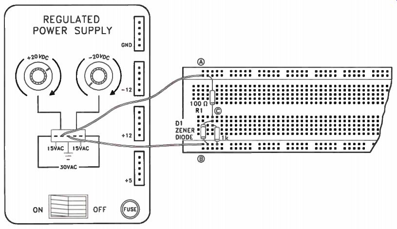
Figure 5-2. Wiring the Zener diode shunt regulator circuit.
Step 7. Connect a 1k, 1/4 -W resistor from point C to point B on the breadboard strip.
This resistor is the load (Rd and is connected in parallel with the Zener shunt regulator.
Step 8. Check your wiring to make sure it is correct and then apply power and turn on the Discovery Lab's power switch.
Step 9. Connect your digital multimeter's negative lead (the black probe) to point B (ground) on the breadboard strip. Leave this connection in place for all of the following steps.
Step 10. Set your digital multimeter to measure about 50 V and measure the voltage at point A. This is the input to the regulator circuit. Note that you can vary this voltage from less than 2 V to about 20 volts. For now, set it to about 15 V and leave it there. Record your reading in the top-left corner of Figure 5-3.
Step 11. Set your digital multimeter to measure about 10-V scale and measure the voltage at point C. This is the input to the regulator circuit. Since the regulator circuit uses a 6-V Zener, you should find a regulated voltage at point C. Record your reading in the top right corner of Figure 5-3.
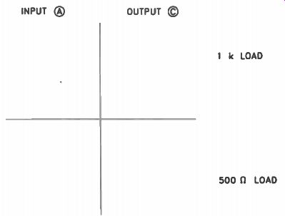
Figure 5-3. For the Zener diode shunt regulator experiment, enter your
measured values in this voltage chart.
Step 12. Now connect another 1k, 1 / 4 -W resistor from point C to point B on the bread board strip. This resistor is in parallel with the existing load and will double the load current, since it's the same value as the original load resistor. Again measure the voltage at point C and record your reading in the bottom-right corner of Figure 5-3. If the regulator is working, the voltage won't change much when you add the extra load. This shows that the regulator has excellent load regulation. Use these measurements to answer Examination Question 5.
Step 13. Measure the input voltage at point A and record your reading in the bottom-left corner of Figure 5-3. Since the Discovery Lab's adjustable DC outputs are regulated, you shouldn't notice much difference with or without the extra load resistor.
Step 14. While the extra load resistor is connected, run the input voltage up and down and notice that it has little, if any, effect on the output voltage, until you turn it down to about half of your preset +15 volts. This shows that the regulator has excellent line regulation.
Step 15. When you finish checking your results, turn off the Discovery Lab and remove the components you installed in steps 5-12 above.
Results
You constructed and analyzed a Zener diode shunt regulator. You checked for load regulation by changing the amount of load resistance applied to the circuit. You also checked for line regulation by changing the input voltage with the Discovery Lab's variable output power supply.
--------------------
Experiment 6: IC Series Regulator
Introduction:
In this experiment, you will use one of your Discovery Lab's variable DC outputs to demonstrate the operation of a three-terminal IC series voltage regulator.
Materials Needed:
For this experiment, you'll need your Discovery Lab with the wires left in place from the previous experiment, your digital multimeter, one 7805 voltage regulator IC, two 1 µF capacitors, two 100 ohm resistors, and a length of hook-up wire.
Procedure
Again, using your Discovery Lab as a base, construct the circuit shown in schematic form In Figure 6-1. Wire the components as shown in Figure 6-2, on the next page.
Step 1. For your personal safety and that of the equipment, unplug the Discovery Lab's power cord before you make these connections.
Step 2. Prepare a 2" length of solid hook-up wire by removing 1/4" of insulation from each end.
Step 3. Connect this wire from point A to point D on the breadboard strip.
Step 4. Bend the leads of a 7805 voltage regulator IC, as shown in Figure 6-3, on the next page. Bend the center (ground) lead toward the front (marked side) of the IC, and bend the outer leads toward the back of the IC.
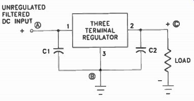
Figure 6-1. The three-terminal IC series regulator circuit.
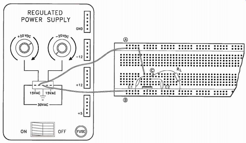
Figure 6-2. Wire the three-terminal IC voltage regulator.
Step 5. Carefully insert the three leads of the 7805 IC into the breadboard so that the center lead contacts point B, the left (IN) lead contacts point D, and the right (OUT) lead contacts point C. You may find it helpful to use a pair of long nose pliers to insert the leads into the socket.
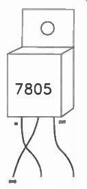
Figure 6-3. Bend the leads of the 7805 voltage regulator IC as shown.
Step 6. Connect a 1 µF capacitor from point A to point B on the breadboard socket.
Make sure the positive (+) lead of the capacitor is connected to point A. Step 7. Connect another 1 uF capacitor from point C to point B on the breadboard socket. Make sure the positive (+) lead of the capacitor is connected to point C. Step 8. Connect a 100 ohm, 1-W resistor (Rd from point C to point B on the breadboard socket.
Step 9. Once again connect your digital multimeter's negative lead (the black probe) to point B (ground) on the breadboard strip.
Leave this connection in place for all of the following steps.
Step 10. Set your digital multimeter to measure about 50 V and measure the voltage at point A. This is the input to the regulator circuit. Note that you can vary this voltage from less than 2 V to about 20 volts. For now, set it to about 15 V and leave it there. Record your reading in the top-left corner of Figure 6-4.
Step 11. Set your digital multimeter to measure about 10 V and measure the voltage at point C. This is the input to the regulator circuit. Since the regulator circuit uses a 7805 IC, you should find nearly a regulated voltage at point C. Record your reading in the top-right corner of Figure 6-4. Use this reading to answer Examination Question 6.
Step 12. Now connect another 100 1/, 1-W resistor from point C to point B on the bread board strip. This resistor is in parallel with the existing load and will double the load current, since it's the same value as the original load resistor. Again, measure the voltage at point C and record your reading in the bottom-right corner of Figure 6-4. If the regulator is working, the voltage won't change much when you add the extra load.
Step 13. Measure the input voltage at point A and record your reading in the bottom-left corner of Figure 6-4. Since the Discovery Lab's adjustable DC outputs are regulated, you shouldn't notice any difference with or without the extra load resistor. This shows that the regulator has excellent load regulation.
Step 14. While the extra load resistor is connected, run the input voltage up and down and notice that it has little, if any, effect on the output voltage, until you turn it down to about half of your preset +15 volts. This shows that the regulator has excellent line regulation.
Step 15. When you finish checking your results, turn off the Discovery Lab and remove the components you installed in steps 2-12 above.
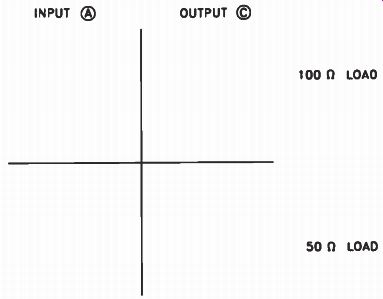
Figure 6-4. For the IC series regulator experiment, enter your measured
values in this voltage chart.
Results:
You constructed and analyzed an IC series regulator. You checked for load regulation by changing the amount of load resistance applied to the circuit. You also checked for line regulation by changing the input voltage with the Discovery Lab's variable output power supply.
-----------------
Experiment 7: NPN Transistor Voltage Amplifier
Introduction In this experiment, you will construct a common-emitter amplifier stage using an NPN transistor and analyze its DC operation.
Materials Needed:
For this experiment, you'll need your Discovery Lab, your digital multimeter, one 2N3904 transistor, two 100 ohm resistors, two 1-k resistors, and a length of hook-up wire.
Procedure:
Using your Discovery Lab as a base, con struct the circuit shown in schematic form in Figure 7-1. Wire the components as shown in Figure 7-2.
Step 1. For your personal safety and that of the equipment, unplug the Discovery Lab's power cord before you make these connections.
Step 2. Prepare three 6" lengths of solid hook-up wire by removing 1 / 4" of insulation from each end of each wire.
Step 3. With one of the three 6" wires, connect the Discovery Lab's GND point to point A on the breadboard strip.
Step 4. With another of the three 6" wires, connect the Discovery Lab's +12-V output to point B on the breadboard strip.
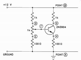
Figure 7-1. An NPN transistor connected in a common emitter amplifier
circuit.
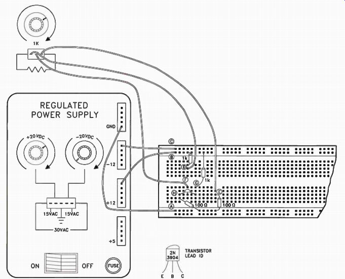
Figure 7-2. Wiring the common-emitter amplifier.
• Step 5. With the last of the three 6" wires, connect the Discovery Lab's -12 V output to point C on the breadboard strip.
Step 6. Prepare three 9" lengths of solid hookup wire by removing 1/4 " of insulation from each end of each wire.
Step 7. With one of the three 9" wires, connect the left terminal of the Discovery Lab's 1-k pot to point D on the breadboard strip.
Step 8. With another of the three 9" wires, connect the right terminal of the Discovery Lab's 1-k pot to point E on the breadboard strip.
Step 9. With the last of the three 9" wires, connect the center terminal of the Discovery Lab's 1-k pot to point F on the breadboard strip.
Step 10. Connect a 1-k resistor from point B to point D on the breadboard strip.
Step 11. Connect a 100 ohm resistor from point E to point A on the breadboard strip.
Step 12. Connect a 1-k resistor from point B to point G on the breadboard strip.
Step 13. Connect a 100 resistor from point H to point A on the breadboard strip.
Step 14. Install the 2N3904 NPN transistor on the breadboard strip. Connect the collector to point G, the base to point F, and the emitter to point A of the breadboard strip.
Step 15. Connect the negative (-) lead of your digital multimeter to point A of the breadboard strip.
Step 16. Connect the positive (+) lead of your digital multimeter to point B of the breadboard strip.
Step 17. Set the digital multimeter to its 50-V range.
Step 18. Check your wiring to make sure it is correct and then apply power to the Discovery Lab and turn on its power switch.
The digital multimeter should immediately register about 12 V. If there is no reading, quickly turn off the power and recheck your connections.
Step 19. Assuming the +12-V power supply is working properly, make the following tests with the power on.
Step 20. Read the DC voltage at points F (input) and G (output) of the breadboard strip.
Take each reading with the 1 k pot fully clock wise, centered, and fully counterclockwise.
Record your readings in the table in Figure 7-3.
Step 21. Turn the 1-k pot fully clockwise and again read the voltage at point G (the collector of the transistor). Use this measurement to answer Examination Question 7.
Step 22. When you finish checking your results, turn off the Discovery Lab and remove the components you installed in steps 10-14 above. Leave in place the six wires you in stalled in steps 3-9.
Results You constructed a typical amplifier circuit and analyzed its operation under static (dc) conditions. You built and tested a common emitter NPN transistor voltage amplifier and checked it for normal operation. You should have observed that the output voltage swings were opposite in direction to those at the in put, since this is an inverting amplifier circuit.
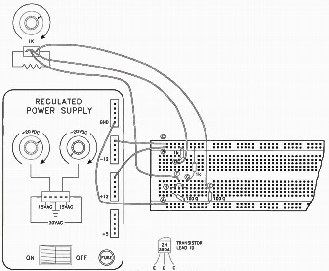
Figure 7-3. For the common-emitter amplifier experiment, enter your measured
values in this voltage chart.
-----------
Experiment 8: IC Operational Amplifier
Introduction
In this experiment, you will construct a two stage amplifier using an IC dual op amp. You will configure one of the two op amp circuits as an inverting amplifier and the other op amp as a voltage follower. You will then analyze the DC operation of the two-stage amplifier.
Materials Needed
For this experiment, you'll need your Discovery Lab with the wires left in place from the previous experiment, your digital multimeter, one 1458 dual op amp IC, one 10k resistor, one 100k resistor, and a length of hook-up wire.
Procedure
Using your Discovery Lab as a base, con struct the circuit shown in schematic form in Figure 8-1, on the next page. Wire the components as shown in Figure 8-2, on the next page.
Step 1. For your personal safety and that of the equipment, unplug the Discovery Lab's power cord before you make these connections.
Step 2. Make sure the six wires installed in steps 3-9 of the previous experiment are still in place.
Step 3. Install the 1458 dual op amp IC on the breadboard strip as shown. Be careful to avoid bending any of the eight leads under the chip.
Step 4. Prepare six 1" and two 3" lengths of solid hook-up wire by removing 1 / 4 " of insulation from each end of each wire.
Step 5. Connect one of the 3" wires from Pin 8 of the 1458 IC to point B on the bread board strip.
Step 6. Connect another of the 3" wires from Pin 4 of the 1458 IC to point C on the breadboard strip.
Step 7. Connect one of the 1" wires from Pin 3 of the 1458 IC to point A on the bread board strip.
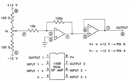
Figure 8-1. A 1458 dual op amp IC used as a two-stage amplifier. The
first stage has a gain of 10; the second stage is a voltage follower,
which provides a low impedance output.
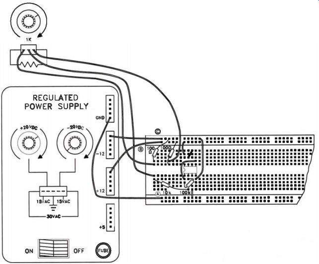
Figure 8-2. Wiring the two-stage IC amplifier circuit.
Step 8. Connect another of the 1" wires from Pin 6 to Pin 7 of the 1458 IC.
Step 9. Connect another of the 1" wires from Pin 1 to Pin 5 of the 1458 IC.
Step 10. Connect a 10k resistor from point F to Pin 2 of the 1458 IC.
Step 11. Connect a 100k resistor from Pin 2 to Pin 1 of the 1458 IC.
Step 12. Connect the negative (-) lead of your digital multimeter to point A of the breadboard strip.
Step 13. Connect the positive (+) lead of your digital multimeter to point B of the breadboard strip.
Step 14. Set the digital multimeter to read about 50 V.
Step 15. Check your wiring to make sure it is correct and then apply power to the Discovery Lab and turn on its power switch.
The digital multimeter should immediately register about 12 V. If there is no reading, quickly turn off the power and recheck your connections.
Step 16. Assuming the +12-V power supply is working properly, make the following tests with the power on. Measure the input (point F) and output (point G) voltages with the 1-k pot turned fully clockwise, centered, and fully counterclockwise. Remember to re verse the leads for negative voltages when using an analog meter. Record your readings in the table in Figure 8-3.
Step 17. Again measure the output voltage at point G with the 1-k pot turned fully counterclockwise. Use this reading to answer Examination Question 8.
Step 18. When you finish checking your results, turn off the Discovery Lab and remove all the wires and components from the bread board strip.
Results:
You constructed a typical two-stage IC amplifier circuit and analyzed its operation under static (DC) conditions.
You built and tested an inverting amplifier and a voltage follower, each implemented with half of a dual op amp IC. You programmed the inverting amplifier for a voltage gain of 10 with the resistor values you used. The two amplifiers were cascaded so that the output of the x10 inverting amplifier fed the input of the voltage follower. As was also the case with the transistor amplifier, you should have observed that the output voltage swings were opposite in direction to those at the input, since this is an inverting amplifier circuit.
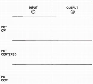
Figure 8-3. For the two-stage IC amplifier experiment, enter your measured
values in this voltage chart.
-------------------
Experiment 9: NPN Transistor Multivibrator Introduction
In this experiment, you will construct a type of oscillator circuit called a multivibrator.
You will build this circuit around two NPN transistors and study its operation.
Materials Needed
For this experiment, you'll need your Discovery Lab, two 2N3904 transistors, two 1-k resistors, two 10k resistors, two 100µF capacitors, two LEDs, and a length of hook up wire.
Procedure
Using your Discovery Lab as a base, con struct the circuit shown in schematic form in Figure 9-1. Wire the components as shown in Figure 9-2.
Step 1. For your personal safety and that of the equipment, unplug the Discovery Lab's power cord before you make these connections.
Step 2. Make sure all wires and components are removed from the breadboard strip. As needed, re-use the cut lengths of solid hook-up wire from previous experiments.
Step 3. Connect a 6" piece of hook-up wire from the Discovery Lab's +5 terminal to point A on the breadboard strip.
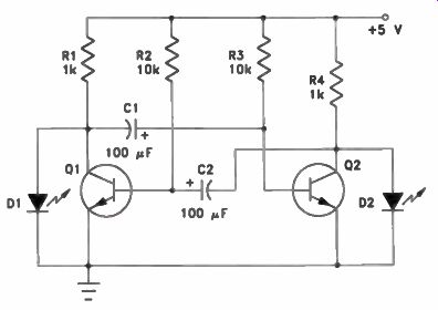
Figure 9-1. Two NPN transistors connected as an astable multivibrator.
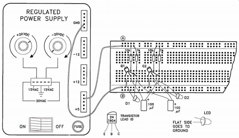
Figure 9-2. Wiring the astable muiti-vibrator circuit.
Step 4. Connect another 6" piece of hook up wire from the Discovery Lab's GND terminal to point B on the breadboard strip.
Step 5. Insert two 2N3904 transistors and orient them as shown. We will call the transistor on the left Q1 and the one on the right Q2.
Step 6. Connect a 1" piece of hook-up wire from the emitter (left lead) of Q1 to ground point B.
Step 7. Connect another 1" piece of hook up wire from the emitter (left lead) of Q2 to ground point B.
Step 8. Connect a 10k resistor from the base (center lead) of Q1 to +5 point A.
Step 9. Connect another 10k resistor from the base (center lead) of Q2 to +5 point A.
Step 10. Connect a 1-k resistor from the collector (right lead) of Q1 to +5 point A.
Step 11. Connect another 1-k resistor from the collector (right lead) of Q2 to +5 point A.
Step 12. Connect a 100 e capacitor from the collector of Q1 to the base of Q2. The plus ( +) lead goes to the base of Q2.
Step 13. Connect another 100 e capacitor from the collector of g2 to the base of Q1.
The plus (+) lead goes to the base of Q1.
Step 14. Connect an LED as D1 from the collector of Q1 to ground. The cathode (flat) side goes to ground.
Step 15. Connect an LED as D2 from the collector of Q2 to ground. The cathode (flat) side goes to ground.
Step 16. Check your wiring to make sure it is correct and then apply power to the Discovery Lab and turn on its power switch.
LEDs D1 and D2 should begin flashing immediately. If they don't, quickly turn off the Discovery Lab and check your wiring.
Step 17. Observe the operation of the flashing lights. Each one is displaying the state of one of the two transistors. When Q1 is conducting, its collector voltage is very low, so LED D1 is dark. When Q1 is cut off, its collector voltage increases, and so LED D1 is lit. Use your observations to answer Examination Question 9.
Step 18. When you finish checking your results, turn off the Discovery Lab and remove all the wires and components from the bread board strip.
Results
Using two NPN transistors, you constructed and tested an astable multivibrator, which generates complementary (equal, but opposite) square wave outputs. Since the oscillation frequency is very low, you were able to see the oscillator's complimentary outputs driving the two LEDs.
Experiment 10: IC Function Generator
• Introduction In this experiment, you will construct a function generator using an IC dual op-amp.
You will configure one of the two op amp circuits as an integrator and the other op amp as a voltage comparator. You will connect these circuits so that each one's output feeds the other's input. You then will observe the output of this oscillator circuit.
Materials Needed
For this experiment, you'll need your Discovery Lab with all the wires from previous experiments removed, one 1458 dual op-amp IC, one 1-k resistor, one 4.7k resistor, four 10k resistors, one 47k resistor, one 10 µF capacitor, an LED, and a length of hook-up Wire.
Procedure
Using your Discovery Lab as a base, con struct the circuit shown in schematic form in Figure 10-1, on the next page. This circuit is quite a bit more complex than others you have built so far. Be very careful to make the connections exactly as shown and position the wiring, especially the resistor leads, to avoid short circuits. Wire the components as shown in Figure 10-2, on page 27.
Step 1. For your personal safety and that of the equipment, unplug the Discovery Lab's power cord before you make these connections.
Step 2. Make sure all wires and components are removed from the breadboard strip.
As needed, re-use the cut lengths of solid hook-up wire from previous experiments.
Step 3. Connect a 6" piece of hook-up wire from the Discovery Lab's GND terminal to ground point A on the breadboard strip.
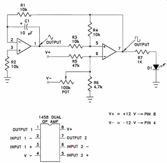
Figure 10-1. A 1458 dual op amp IC used as a function generator. The
integrator is on the left, and the comparator is on the right.
Step 4. Connect another 6" piece of hook up wire from the Discovery Lab's +12 terminal to point B on the breadboard strip.
Step 5. Connect another 6" piece of hook up wire from the Discovery Lab's -12 terminal to point C on the breadboard strip.
Step 6. Install the 1458 dual op amp IC on the breadboard strip as shown. Be careful to avoid bending any of the eight leads under the chip.
Step 7. Connect a 3" piece of hook-up wire from point B on the breadboard strip to Pin 8 of the 1458 IC.
Step 8. Connect another 3" piece of hook up wire from point C on the breadboard strip to Pin 4 of the 1458 IC.
Step 9. Connect a 10k resistor from ground point A on the breadboard strip to Pin 3 of the 1458 IC.
Step 10. Connect a 4.7k resistor from ground point A on the breadboard strip to Pin 6 of the 1458 IC.
Step 11. Connect a 10k resistor between pins 2 and 7 of the 1458 IC.
Step 12. Connect another 10k resistor between pins 5 and 7 of the 1458 IC.
Step 13. Connect another 10k resistor between pins 1 and 5 of the 1458 IC. Step 14. Connect a 47k resistor from point B on the breadboard strip to Pin 6 of the 1458 IC.
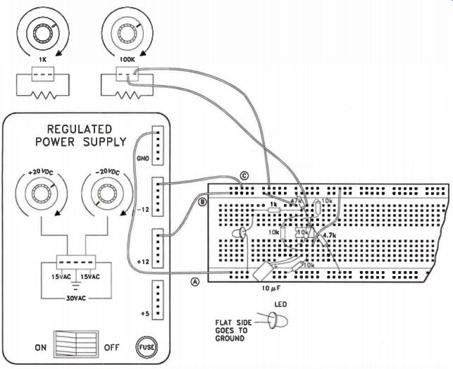
Figure 10-2. Wiring the function generator circuit.
Step 15. Connect a 1-k resistor from Pin 7 of the 1458 IC to the anode of the LED. Connect the cathode (flat) side of the LED to ground.
Step 16. Connect a 101 uF capacitor from Pin 1 to Pin 2 of the 1458 IC. The positive (+) lead should connect to Pin 2.
Step 17. Connect the center terminal of the 100k pot to PM 6 of the 1458 IC. Step 18. Connect the right terminal of the 100k pot to point C on the breadboard strip.
Step 19. Check your wiring to make sure it is correct and then apply power to the Discovery Lab and turn on its power switch.
Rotate the 100k pot from one extreme to another. LED D1 should begin flashing and remain flashing over much of the pot's range.
If it doesn't, quickly turn off the Discovery Lab and check your wiring.
Step 20. Observe the operation of the flashing LED. The lamp is connected to the function generator's square wave output. Rotate the 100k pot from one extreme to the other and note its effect on the flashing LED. Use your observations to answer Examination Question 10.
Step 21. When you finish checking your results, turn off the Discovery Lab and remove the all the wires and components from the breadboard strip.
Results
You built and tested a basic function generator circuit around a 1458 dual op amp IC. You connected one half of the IC (one complete op amp) as an integrator and the other half as a comparator. By connecting these two circuits back-to-back, so that the output of each one feeds the input of the other, you formed a function generator circuit.
The output of the integrator circuit is a triangle waveshape, while the output of the comparator is a square wave. The frequency of both outputs is the same. You used an LED indicator to observe the square wave output and to study the result of changing the value of one of the circuit's resistors.
-----------
Examination Questions
This is Examination Number 4489.
Make sure you print your name, student number, and examination number (Lesson Number) in the space provided on the Answer Form. Be sure to fill in the circles beneath your student number and examination number (Lesson number).
Reminder: A properly completed Answer Form allows us to evaluate your answers and speed the results and additional study material to you as soon as possible. Do not hold your Answer Forms to send several at one time. You may run out of study material if you do not send your answers for evaluation promptly.
1. In Step 7 of Experiment 1, when I measured the voltage across the transformer's secondary winding with the digital multimeter's black lead on point A and the meter's red lead on point C, I found about:
a. 15 Vac.
b. +15 V
c. 30 Vac.
d. +30 V
2. In Step 9 of Experiment 2, when I measured the voltage across RL, I found about:
a. +25 V and 0 Vac.
b. +12 V and 7 Vac.
c. +50 V and 0 Vac.
d. +50 V and 30 Vac.
3. In Step 5 of Experiment 3, when I measured the voltage across RL with the filter capacitor connected, I found about:
a. +20 V and 0 Vac.
b. +20 V and 15 Vac.
c. +40 V and 0 Vac.
d. +40 V and 30 Vac.
4. In Step 6 of Experiment 4, when I measured the voltage across RL with increased input voltage, and with the filter capacitor still connected, I found about:
a. +20 V and 0 Vac.
b. +20 V and 15 Vac.
c. +40 V and 0 Vac.
d. +40 V and 30 Vac.
5. In Step 12 of Experiment 5, when I measured the Zener-regulated voltage across the load resistor, I found about:
a. +0.7 V.
b. +6 V.
c. +25 V.
d. +50 V.
6. In Step 11 of experiment 6, when I measured the IC-regulated voltage across the load resistor, I found about:
a. +0.7 V.
b. +5 V.
c. +6 V
d. +25 V.
7. In Step 21 of Experiment 7, when I measured the transistor amplifier's output voltage with the 100k pot turned fully clockwise, I found about:
a. +1 V
b. +2 V.
c. +10 V.
d. +20V
8. In Step 17 of Experiment 8, when I measured the IC voltage follower's output voltage with the 1-k pot turned fully counterclockwise, I found about:
a. -12 V
b. 0 V.
c. +12 V.
d. +20 V
9. In Step 17 of Experiment 9, when I ob served the operation of the two LEDs driven by the multivibrator, I saw that:
a. LED D1 was lit when LED D2 was dark, and vice versa.
b. Both LEDs flashed on and off together.
c. Only LED D1 flashed.
d. Only LED D2 flashed.
10. In Step 20 of Experiment 10, when I ob served the operation of the LED driven by the function generator, I saw that I could:
a. Change the LED's brightness by adjusting the 100k pot.
b. Start and stop the oscillation of the function generator by adjusting the 100k pot.
c. Not change the oscillator's operation by adjusting the 100k pot.
d. Change both the brightness and blinking rate by adjusting the 100k pot.
-------------------

NRI Graduates Say... "Through NRI, I not only received the experience I was looking for, I also gained the confidence I sought to return to college and upgrade my skills and further my career ambitions. I particularly enjoyed the way you structure the course into smaller sections; it provided me the opportunity to move through the lessons at my own pace without fear of missing something important.
I chose NRI because right from your first correspondence with me I felt as though I had to mail out my application right away. It sounded so exciting, I couldn't wait to get started, which is what I did. I looked forward to each new lesson because it felt so good to read and comprehend almost immediately, and those times I didn't understand, after one or two re-reads, I got it. I only needed the help of an instructor once, but his reply was prompt and clear. I was almost sorry once I had completed the course, but I've since enrolled in college and my studies continue. Would I recommend NRI to others? I already have! I sing your praises often to workmates and I think a couple of them have applied.
So all I can say is thanks to you I am far better off than I was three years ago, and my future looks bright. I'm sure there are many others who feel as I do."
-Tyrone J. Leslie Groton, Connecticut
| Top of Page | PREV | NEXT | Article Index |