AMAZON multi-meters discounts AMAZON oscilloscope discounts
It's important to understand that the basic parts of any control system will have the same names and provide the same functions regardless if the controller is pneumatic, op amp, or a microprocessor-based system. ill. 1 shows the basic parts of a control system shown in a block diagram. It will be easier to understand these basic parts of a control system if they are applied to a specific application. An electric heating system that's used to dry paint is shown in ill. 2 and it will be used for this explanation. From the block diagram notice that the system starts with a setpoint (SP) signal. The SP is the desired value or the desired temperature. E.g., if we wanted the desired temperature of the heating system to be 280°F, the SP would be adjusted to 280°F.
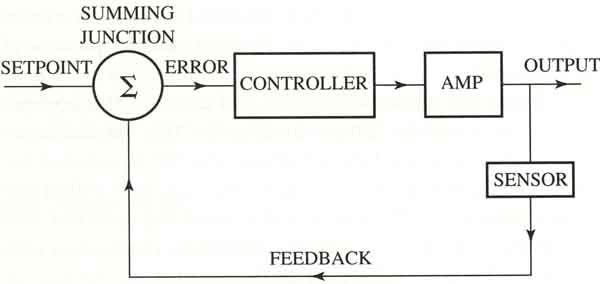
Above: ill. 1 Block diagram of a control system.
The next part of the control system that we will examine is the process variable (PV), which is the signal that comes from the sensor. E.g., in the heating system, the PV is the signal from the thermocouple which is the sensor for this system. The PV is also called the feedback signal and it's the present value or actual value of the temperature at the instant the sensor reading takes place. Since the sensor reading is continuous, the PV will change continually to indicate the changing temperature of the system.
The summing junction is the place in the control system where the SP is compared to the PV. This means that if the SP is 280°F and the PV signal indicates the actual temperature is 270°F, the difference is 10°F. The summing junction is identified by the Greek letter sigma (Σ).
The difference between the SP and the PV is called error. The error can be a positive value if the SP is larger than the PV, or it can be a negative value if the SP is smaller than the PV.
The controller will use gain, reset, and rate to adjust the output signal in response to the amount of error. Gain, reset, and rate are also called proportional, integral, and derivative (PID). The PID values can be adjusted to change the speed of response for the system. E.g., a gain value, can be used to make the output change the temperature at a given response rate of 1°F per minute, or it can be set to provide a change of 3°F per minute. The function of gain, reset, and rate will be explained in detail later in this section.
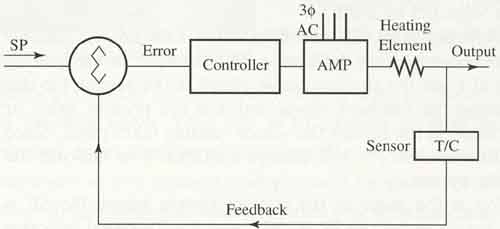
Above: Fig 2. The control diagram for the industrial paint-drying oven.
PREV.: Intro
NEXT: An
Application Example