AMAZON multi-meters discounts AMAZON oscilloscope discounts
An Electric Heating Application
The electric heating system in this application is a paint-drying oven. The control diagram of the paint-drying oven is shown in ill. 2 below. In this application automotive trim parts are manufactured in a plastic press and then placed on a continuous overhead conveyor line. The conveyor line moves the parts through a paint booth where robots apply paint to the parts. The freshly painted parts are then moved through an electric paint-drying oven. The paint-drying oven uses electric heating coils to provide the proper amount of heat for the oven.
From the control diagram notice the components for the parts of the basic control system. The controller for this application is a single-point electronic controller that has a keypad where the SP is entered by the operator. The sensor for this system is a thermocouple and it's also called the process variable. The SP is compared to the PV signal at the summing junction, which is inside the controller. The signal that comes from the summing junction is called the error signal, and it's sent to the controller part of the system.
The controller sends an output signal to an amplifier that controls the electric heating elements. The amplifier for this system is a three-phase current controller that adjusts amperage to the heating elements from 0 - 100% with a 0 - 1 Volts DC signal. The controller sends the 0 - 10 volt signal as an output signal to the amplifier.
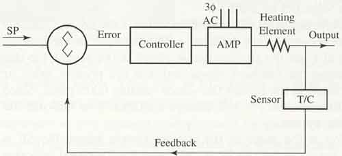
Above: Fig 2. The control diagram for the industrial paint-drying oven.
PREV.: Parts of a Typical Control
System
NEXT: A Typical Open-Loop System