AMAZON multi-meters discounts AMAZON oscilloscope discounts
An electrical network initiates at the point of generation. Electrical power is generated by converting the potential energy available in certain materials into electrical energy.
AMAZON multi-meters discounts AMAZON oscilloscope discountsThis is either done by direct conversion of kinetic energy, e.g. wind- or water turbines, or creating steam to drive the turbines, e.g. coal- or nuclear boilers.
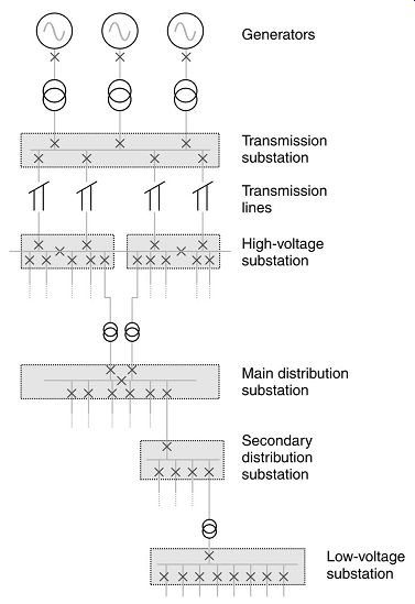
++++ Typical electrical power network.
The electrical powers generated are either transferred onto a bus to be distributed (small scale), or into a power grid for transmission purposes (larger scale). This is done either directly or through power transformers, depending on the generated voltage and the required voltage of the bus or power grid. The next step is power transmission, whereby the generated electrical potential energy is transmitted via transmission lines, usually over long distances, to high-voltage (HV) substations. High-voltage substations will usually tap directly into the power grid, with two or more incoming supplies to improve reliability of supply to that substation's distribution network. Electrical transmission is normally done via high to extra high voltages, in the range of 132-800 kV. Mega volt systems are now being developed and implemented in the USA. The longer the distance, the more economical higher voltages become.
AMAZON multi-meters discounts AMAZON oscilloscope discountsWhy would high-voltage transmission be more economical than lower voltages the longer the transmission distance, and be less economical for short distances?
Normally, the transmission voltage will be transformed at the HV substation to a lower voltage for distribution purposes. This is due to the fact that distribution is normally done over shorter distances via underground cables. The insulation properties of three-phase cables limit the voltage that can be utilized, and lower voltages, in the medium-voltage range, are more economical for shorter distances.
This is a schematic illustration of a typical power grid:
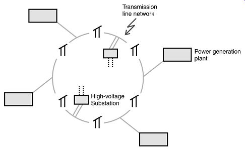
++++ Typical power grid.
Critical medium-voltage (MV) distribution substations will generally also have two or more incoming supplies from different HV substations. Main distribution substations usually supply power to a clearly defined distribution network, For example, a specific plant or factory, or for town/city reticulation purposes.
Power distribution is normally done on the medium-voltage level, in the range of 3.0-35 kV. Three-phase power is transferred, mostly via overhead lines or 3-core MV power cables buried in trenches. Single-core-insulated cables are also used, although less often.
Low-voltage distribution is also done over short distances in some localized areas.
A power distribution network will therefore typically include the following:
• HV/MV power transformer(s) (secondary side)
• MV substation and switchgear
• MV power cables (including terminations)
• MV/LV power transformer(s) (primary side). The distribution voltage is then transformed to low voltage ( LV), either for lighting and small power applications, or for electrical motors, which is usually fed from a dedicated motor control center (MCC).
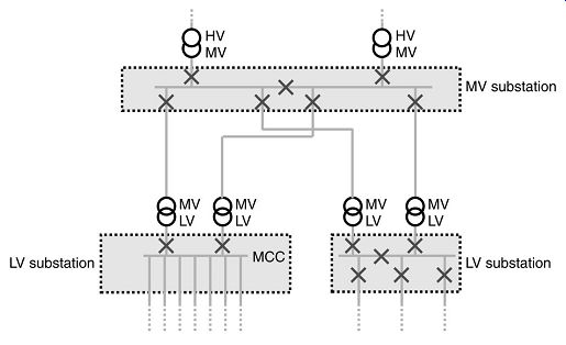
++++ Typical power distribution network
Note: Voltage levels are defined internationally, as follows:
• Low voltage: up to 1000 V
• Medium voltage: above 1000 V up to 35 kV
• High voltage: above 35 kV Supply standards variation between continents by two general standards have emerged as the dominant ones:
• In Europe IEC governs supply standards
The frequency is 50 Hz and LV voltage is 230/400 V
• In North America
IEEE/ANSI governs supply standards
The frequency is 60 Hz and the LV voltage is 110/190 V. Overhead lines are far cheaper than underground cables for long distances, mainly due to the fact that air is used as the insulation medium between phase conductors, and that no excavation work is required. The support masts of overhead lines are quite a significant portion of the costs, that is the reason why aluminum lines are often used instead of copper, as aluminum lines weigh less than copper, and are less expensive. However, copper has a higher current conducting capacity than aluminum per square mm, so once again the most economical line design will depend on many factors.
Overhead lines are by nature prone to lightning strikes, causing a temporary surge on the line, usually causing flashover between phases or phase to ground. The line insulators are normally designed to relay the surge to ground, causing the least disruption and/or damage. This is of short duration, and as soon as it’s cleared, normal operation may be resumed. This is why sophisticated auto-reclosers are employed on an increasing number of overhead lines.
Overhead lines have the following properties:
Advantages:
- • Less expensive for longer distances
- • Easy to locate fault
Disadvantages:
- • More expensive for shorter distances
- • Susceptible to lightning
- • Not environment-friendly
- • Maintenance intensive
- • High level of expertise and specialized equipment needed for installation
Underground (buried) cable installations are mostly used for power distribution in industrial applications. They have the following properties:
Advantages:
- • Less expensive for shorter distances
- • Not susceptible to lightning
- • Environment-friendly
- • Not maintenance intensive
Disadvantages:
- • Expensive for long distances
- • Can be difficult to locate fault
The focus of this manual will be on MV power distribution, specifically practical considerations regarding MV switchgear, power cables, power factor correction and computer simulation studies.
| Top of Page | PREV: Article Index and Overview | NEXT: Medium-voltage switchgear | Index |