AMAZON multi-meters discounts AMAZON oscilloscope discounts
Standards
Standards in Europe and many other 50 Hz countries are governed by the IEC. Various bureau of standards have adopted many of the IEC standards e.g IEC 87.

above: Siemens MV switchgear.
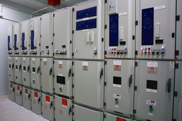
above: ABB's Unigear medium voltage switchgear

above: Eaton's VacClad-W Metal-clad switchgear with Eaton's VCP-W vacuum breakers, provides centralized control and protection of medium-voltage power equipment and circuits in industrial, commercial and utility installations involving generators, motors, feeder circuits, and transmission and distribution lines.
In North America, the standards are set by ANSI and the IEEE. The standards and the way switchgear is tested vary from country to country. It’s therefore important to verify what standard is being called for in a specification or is used by the manufacturer. Variations in standards also affect the price of equipment.
AMAZON multi-meters discounts AMAZON oscilloscope discountsSwitch board layout
 Switch boards can be designed to have various configurations. This depends
on the reliability, fault level and the flexibility required. Examples:
Switch boards can be designed to have various configurations. This depends
on the reliability, fault level and the flexibility required. Examples:
 • Single busbar with only one busbar section (no flexibility and low reliability)
• Single busbar with two sections (improved flexibility and reliability with highest fault level if section maker is closed)
• Single busbar with three sections (excellent flexibility and reliability)
• Double busbar with one or more sections (good flexibility and reliability). The busbar layout may require a break before transfer from one busbar to the next.
AMAZON multi-meters discounts AMAZON oscilloscope discountsRatings
Manufactured medium-voltage (MV) switchgear panels are rated according to the following main specifications:
Nominal voltage: This is the designed average voltage of a system, e.g. 11 kV. The actual voltage will typically fluctuate between 10.5 and 11.5 kV (95-105%).
Rated voltage: This is the voltage level at which the equipment will be expected to perform at continuously under normal operating conditions, e.g. 12 kV for a system with a nominal voltage of 11 kV.
The rated voltage will determine the insulation properties of the panel. Each main component, including individual circuit-breakers, busbars, cable terminations, etc., must be rated to this voltage, or higher. ('Main' components refer to those components that form part of the main voltage circuit of the panel, as opposed to the control circuit.) E.g., if a 7.2 kV circuit-breaker is installed in a 12 kV panel, it will mean that the whole panel is rated only 7.2 kV.
The normal practice is to rate switchgear panels 10% higher than the required nominal voltage, e.g. 12 kV for an 11 kV system, 36 kV for a 33 kV system, etc.
Power frequency withstand voltage:
This is the 50 or 60 Hz voltage that the switchgear can with stand for 1 min. For 12 kV related equipment, the applied test voltage is 28 kV. Switchgear manufacturers use this test to prove the insulation of their equipment after manufacture in routine testing.
Commissioning engineers also use this test to prove the integrity of the equipment before switching on the power. This test is also known as a pressure test.
Impulse voltage:
This is the highest peak voltage the equipment will be able to withstand for a very short period of time, as in the case of a voltage peak associated with lightning, switching or other transients, e.g. 95kV for 12kV equipment.
BIL standards are set by IEC 60.
The same principle as above applies, i.e. the impulse voltage rating of the panel is equal to the rating of the lowest rated main component.
The impulse level that a panel will experience may be controlled by installing surge suppressers, which will limit the peak voltage to a certain level.
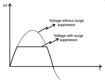
++++1. Impulse voltage
In limiting the peak voltage, e.g. 45kV, the surge arrestor will conduct a large current, say 10kA to ground.
Surge arrestor:
Surge arrestors are installed at the transition point between e.g. an overhead line and a transformer, and as close to the transformer terminals as possible.
Surge arrestors are also installed as motor terminals and on the ends of overhead lines.
They are unusually connected between phases and ground.
Three types of surge arrestors are used:
1. Rod spark gapped
2. Multiple gapped arrestors
3. Zinc (metal) oxide surge arrestors.
In applying surge arrestors the voltage rating, lighting density and the surge rating should be considered in determining the insulation coordination of the power system.
Full load current:
This is the maximum load current that may pass continuously through the switchgear panel. Contrary to the voltage rating, not every main component needs to have the same current rating. Every individual circuit breaker or switch will be rated according to the maximum load current that will pass through it. The incoming circuit-breaker/disconnector and the main busbars will usually be rated the same. This value is obtained by adding all the individual feeder ratings, multiplied by a load or diversity factor. This factor is smaller than one, and is determined by the types of loads connected to the panel. Individual loads won’t run at full capacity simultaneously, hence the load factor. This calculation can be illustrated as follows:
A good estimate of the load factor can be done by looking at the historical values recorded for the relevant feeders, if available.
Due to economy of scale, MV circuit-breakers/disconnectors are manufactured in a few standard sizes, for example 630 A, 1250A, 1600A, 2000A and 2500A according to IEC standards.
Fault current:
The magnitude of fault current that a switchgear panel must withstand is not determined by the load connected to it, but by the properties of the supply to it. Usually, a MV panel will be supplied via a HV/MV transformer(s). This transformer will then determine the magnitude of the fault currents that may flow through the panel.
Electrical faults usually occur due to breakdown of the insulating media between live conductors or between a live conductor and ground. This breakdown may be caused by any one or more of several factors, e.g. mechanical damage, overheating, voltage surges (caused by lightning or switching), ingress of a conducting medium, ionization of air, deterioration of the insulating media due to an unfriendly environment or old age, or misuse of equipment. Faults are classified into two major groups: symmetrical and unbalanced (asymmetrical). Symmetrical faults involve all three phases and cause severe fault currents and system disturbances. Unbalanced faults include phase-to-phase, phase-to ground, and phase-to-phase-to-ground faults. They are not as severe as symmetrical faults because not all three phases are involved. The least severe fault condition is a single phase-to-ground fault with the transformer neutral grounded through a resistor or reactor.
However, if not cleared quickly, unbalanced faults will usually develop into symmetrical faults. These different types of faults are illustrated.
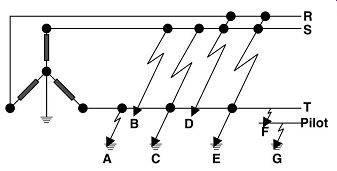
++++ 2. Electrical fault types.
In distribution systems with ?/? (HV/mV) connection and the star point solidly grounded, the single-phase fault current may be higher than the three-phase symmetrical fault current due to the zero sequence reactance of the transformer being lower than the positive sequence reactance.
Switchgear needs to be rated to withstand and break the worst possible fault current, which is a solid three-phase short-circuit close to the switchgear. 'Solid' means that there is no arc resistance. Normally arc resistance will be present, but this value is unpredictable, as it will depend on where exactly the fault occurs, the actual arcing distance, the properties of the insulating medium at that exact instance (which will be changing all the time due to the heating effect of the arc), etc.
Arc resistance will decrease the fault current flowing.
Exact calculations of prospective fault currents can be quite complex, and are usually performed with the aid of computer simulation software. However, when a few allowable assumptions are made, approximate fault currents can be determined quite easily and quickly with pen and paper (plus calculator, preferably!). These approximate values will be conservative, giving the worst case, and can therefore be confidently used for the ratings of switchgear panels.
These assumptions are the following:
• Assume the fault occurs very close to the switchgear. I.e., the cable impedance between the switchgear and the fault may be ignored.
• Ignore any arc resistance.
• Ignore the cable impedance between the transformer secondary and the switchgear, if the transformer is located in the vicinity of the substation. If not, the cable impedance may reduce the possible fault current quite substantially, and should be included for economic considerations (a lower-rated switchgear panel, at lower cost, may be installed).
• When adding cable impedance, assume the phase angle between the cable impedance and transformer reactance as zero, hence the values may be added without complex algebra, and values readily available from cable manufacturers' tables may be used.
• Ignore complex algebra when calculating and using transformer internal impedance.
Fault currents are then easily calculated as follows:
Example 1 (ignoring cable impedance)
Ignoring cable impedance means that the fault is actually calculated directly on the transformer's terminals. The magnitude of the fault current is then only limited by the transformer's internal impedance, which is usually indicated by a percentage value on the nameplate of the transformer. This value expresses the impedance value as a percentage of the base value. Calculation:
Transformer ratings:
Primary voltage: Vp = 132 kV
Secondary voltage: Vs = 11 kV, Capacity: S = 20 MVA
Impedance: Z = 10%; Calculation of base value, Zb:
Manipulation of the above formulas will give a quick reference formula to determine the fault current at the secondary terminals of the transformer:
When more than one transformer is connected in parallel, feeding a switchboard, the fault currents of the transformers are added to give the fault current at the switchboard. For example, if two transformers, with ratings as in the above example, are connected in parallel, the fault current will be 20 992A. The smaller the transformer, the smaller the error of this approximation.
Example 2 (with cable impedance)
When the switchgear is situated quite some distance away from the transformer(s), the cable impedance needs to be taken into account to arrive at a realistic value. The fault current will be lower with additional impedance in the circuit, therefore this may be necessary for economic reasons, so as not to overrate new equipment at additional (unnecessary) cost.
The quickest and easiest way to bring cable impedance into the calculation is to simply add the cable impedance, which is usually a ohm/km value in the cable manufacturer's data table, to the transformer reactance (adjusting for line to phase values). This is an approximate value, as complex algebra should be used to add the impedance values, but it’s usually accurate enough to determine required switchgear ratings.
Calculation:
Take the same transformer ratings as in the above example. Assume the cable distance between the transformer and the switchgear as 6000m. The cable has the following properties:
Type: Copper conductors, XLPE insulated.
Size: 185 mm^2
Current rating: 410A
Impedance: 0.1548 ohm/km
Four cables are installed in parallel between the transformer and switchgear to achieve the required current rating. Transformer reactance (as per above example): Tr
0.605 Z =? Cable impedance:
Therefore, if two transformers would feed in parallel to the switchboard in this example, the total fault current would be 15 172 A, and a switchgear panel rated 20 kA would be sufficient; whereas in the previous example a higher rating than 20 kA would be required.
This fault current rating that the switchgear must withstand, is not for an indefinite time, but is normally rated for 1 s or 3 s. The reason for this is that the electrical protection should operate within this time, clearing the fault. Even if the main protection should fail, enough time should be reserved for the back-up protection to function, avoiding severe damage to the switchgear panel. Sufficient time is also allowed for the circuit breaker tripping time.
The fault current rating will then be specified as a current and time rating, e.g. 20 kA, 3s. This means that the panel will be able to withstand a three-phase through fault current of 20 kA for a continuous period of 3 s. The fault current rating actually refers to two properties:
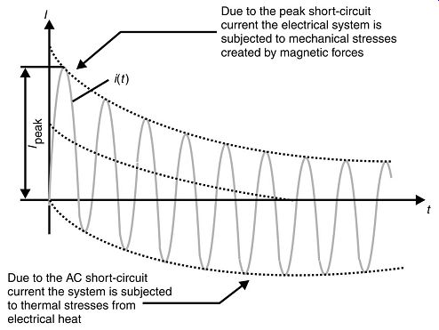
1. The amount of electrical energy the panel can absorb, according to the formula, E = I^2 t. Exceeding this energy limit will cause thermal damage to the panel, and the conductors will melt. Therefore, there is quite a difference between a rating of, for example, 20kA for 1s, and 20kA for 3s. A panel rated for 20kA, 1s will only be able to withstand 11.5 kA for 3s, according to the following calculation:
However, a panel rated for 20kA, 3s won’t necessarily be able to withstand 34.6kA for 1s (according to the same formula), due to the second property involved with fault currents, namely electromechanical stresses.
2. Electromechanical stresses in a switchgear panel arise due to the phenomenon that current flowing in the same direction will cause an electromagnetic field that will assert an attracting force between the current-carrying conductors. In the case of fault currents, this force between the adjacent busbars can be so large that the busbars can be torn loose of their supports, causing extensive damage to the panel.
This force is proportional to the square of the instantaneous current flowing.
Therefore, the mechanical construction of the panel (busbar supports, etc.) will impose an upper limit on its fault current rating, irrespective of the time rating.
The peak asymmetrical current rating, including fall DC offset, is used to determine the maximum electromechanical stresses. It can be seen from the examples that, for MV applications, even long cable distances make only a marginal difference to the fault current rating. This is due to the fact that MV distribution usually involves large cable sizes, with several cables often installed in parallel, with low cable impedance as a result. It’s for this reason that the effect of cable impedance is often ignored in MV fault calculations for distribution purposes, except in borderline cases, or where long distances are involved, or in the case of small size cables.
When small MV cables severely reduce the fault current rating, the chances are good that the cable itself won’t be able to handle the fault current. This is shown in the next section on power cables. Each individual switch as well as the busbars of a switchgear panel must be rated to withstand the prospective fault current. Huge mechanical forces are present in the current carrying equipment when large fault currents flow, due to electromagnetism. Therefore, the fault current rating don’t only refer to the electrical properties of the equipment, but also to their ability to withstand these mechanical forces.
MV switchgear equipment is rated according to the current allowed to pass through it (load or fault current), as well as a 'making' and 'breaking' value. The 'making' current rating is the value of current that the switch may close onto, i.e. the current flowing immediately when the switch is closed. The 'breaking' rating is the value of current already flowing that the switch may interrupt.
Why a 'making' rating, as the current flowing immediately before the switch is closed must be zero (circuit is still open)?
DC offset:
The phenomenon called 'DC offset' should be taken into account when rating circuit breakers. This phenomenon occurs due to the presence of inductive reactance in the system.
++++3. Illustration of DC offset.
The peak current value will depend on the power factor of the system at the time of the fault. This maximum practical value of this peak current is 2.55 times the RMS fault current, as determined by the system impedance.
Although the peak currents associated with the DC offset is of relative short duration, they must be taken into consideration when rating switchgear panels, as additional mechanical stresses are caused by the electromagnetic forces associated with these high peak currents.
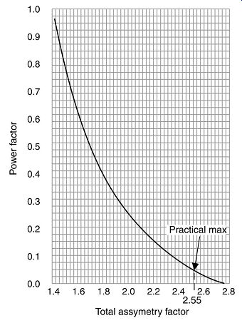
++++4. Asymmetry factor chart.
The rate of decay of the DC offset, is dependent on the relationship L/R of the system. The higher the inductance, the slower the rate of decay.
Normally, the DC offset will decay to zero within the first 3 to 4 cycles. Therefore, at the instant that the circuit breaker opens, these peaks have all but disappeared, and it won’t be a cause for concern.
However, when a circuit breaker is installed close to high-inductive sources, like generators and large induction motors, the current waveform may still be substantially asymmetrical at the instant of the circuit breaker opening. This may cause the breaker to interrupt a higher current value than it was rated for, and the DC offset may cause an extended arcing period within the breaker. The resultant thermal energy may be higher than the breaker can withstand, with the result that the breaker may blow up.
Therefore, for these applications, a specialized generator circuit breaker should be installed, which is designed to withstand these factors.
Regulations:
The Wiring Rules stipulates the following for switchgear above 1000V:
The switching device shall be capable of performing at least the following operating functions:
- • Make and break full-load current
- • Carry the prospective fault current
- • Make prospective fault current
- • If fitted with protection devices, also break prospective fault current
A manually operated switch need not be capable of breaking the prospective fault current.
A switch which won’t make prospective fault current may be approved where satisfactory interlocking is provided.' Standard fault current ratings for switchgear include:
- • 16 kA
- • 20 kA
- • 25 kA
- • 31.5 kA
- • 40 kA
- • 50 kA
- • 60 kA
The Bottom Line ...
MV electrical switchgear units should provide centralized control and protection of medium-voltage power equipment and circuits in industrial, commercial, and utility installations involving generators, motors, feeder circuits, and transmission and distribution lines.
These medium voltage switchgear offerings should include both metal-enclosed and metal-clad options, utilizing either switch or breaker technology. In continuing our long-standing tradition of innovating to meet our customer's needs, OEM manufs., such as Eaton, offer a wide variety of configurations, standard drawing packages, arc-resistant and space-saving solutions. In addition, these agile designs offer the industry's highest power density and most flexible suite of options.
All major components are often manufactured by the OEM, providing a single point of contact and accountability for the equipment's performance, assuring world-class quality, coordination, reliability and service. A Load Interrupter (MVS) metal-enclosed switchgear provides safe, reliable switching and fault protection for medium voltage circuits rated from 5 kV through 38 kV.
Load Interrupter Switchgear (MVS)
Metal-Enclosed Breaker (MEB)
Metal Enclosed Front Accessible Switchgear (MEF)
| Top of Page | PREV: Power distribution: Introduction | NEXT: Medium-voltage switchgear--part 2 | Index |