AMAZON multi-meters discounts AMAZON oscilloscope discounts
Types of MV (medium-voltage) switchgear
Switchgear types are classified according to function and method of insulation.
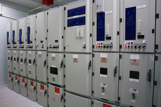
above: ABB's Unigear medium voltage switchgear
Function: Different terms are used to describe switchgear in different parts of the world. However, the following are most accepted terms recognized internationally.
Switch: A switch is a piece of equipment used to open an electric circuit by a mechanical action, interrupting the flow of current, without causing permanent damage to the equipment when it’s used as designed for. A switch may either be a disconnector/isolator or circuit breaker.
Disconnector/Isolator: The term disconnector or isolator is used to describe a device that is designed to open the electric circuit manually (or by manual command) under normal operating conditions. It may either be an off-load or on-load disconnector/isolator.
'Off-load' means the device is designed to open the circuit without any current flowing.
AMAZON multi-meters discounts AMAZON oscilloscope discountsThe current rating of an off-load isolator will refer only to the value of current allowed to continuously pass through the device. The making- and breaking current rating will be zero.
'On-load' means the device may open the circuit with normal load current flowing, up to the full load current rating of the device. The continuous- and breaking current ratings will usually be the same, equal to the full load current rating of the device. Modern disconnectors usually have a short-circuit making rating in the region of 25 kA. However, the disconnector won’t be able to handle this current for any sustained period of time; hence the current must swiftly be interrupted by a protective device, namely a fuse or a circuit breaker.
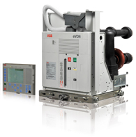
AMAZON multi-meters discounts AMAZON oscilloscope discountsCircuit breaker: A circuit breaker (CB) is designed to open an electric circuit under overcurrent or fault conditions. This will usually occur upon a trip signal from a protection relay. A CB will have a continuous full load current rating, a fault current rating for a limited time, as well as a fault making- and breaking rating.
The CB opens its main contacts through a mechanical action. The contacts are kept closed by virtue of mechanical spring pressure. When a trip signal is received, a latch is drawn by a magnetic field set-up by the tripping coil, the spring pressure is released instantly, and the contacts separate. Due to the mechanical actions involved, a certain fixed amount of time (in ms) elapses from the time the trip command is given until such time as the main contacts actually separate.
Additional to this, there is a short period of arcing when the contacts separate, during which time current continues to flow. Therefore, the total tripping (or breaking) time is defined as follows: CB breaking time opening time arcing time =+
'Opening Time' represents the time between the instant of application of the tripping signal to the instant of mechanical separation of the main contacts.
'Arcing Time' is the time between the instant of mechanical separation of the main circuit breaker contacts to the instant of arc extinction and hence zero current flow.
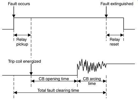
++++5. Total fault clearing time.
Modern circuit breakers have total breaking times between 1 and 5 cycles (40-100 ms).
CB behavior under fault conditions Before the occurrence of a short circuit, normal load current will be flowing through the CB. This could be regarded as zero when compared to the level of the fault current that would flow. At the instant of the fault, the current will rapidly rise to the maximum value allowed by the network properties. Due to the presence of reactance in the power network, the first few cycles be off-set from the center, oscillating around a fast-decaying axis above the zero line.
This phenomenon is called the DC off-set, or DC transient. The magnitude of the first cycle will depend on network conditions, but may be up to 2.55 times the value of the 'sustained' fault current, i.e. the fault current that will continue to flow until it’s interrupted. The rate of decay of the DC transient will depend on the ratio L/R, i.e. the ratio of system inductance to resistance as seen at the point of the fault.
Under a short circuit or fault condition, fault current flows - that has a magnitude which is determined by the network parameters. Upon the breaker tripping, the current is interrupted at the next natural current zero (cyclic point occurring twice a cycle). The network reacts by transient oscillations that give rise to the transient recovery voltage (TRV) across the circuit breaker main contacts.
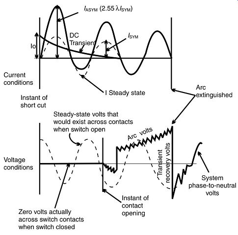
++++6. Behavior under fault conditions.
The insulating medium ensures that the TRV does not cause a flash-over between the contacts and a recurrence of current flow.
The circuit breaker has been designed to withstand and interrupt very high fault currents. Fault current operation places quite high electrical and mechanical stresses on the CB components. For this reason, MV CB life is typically limited to approximately 100 short-circuit operations, depending on the specific type.
Furthermore, circuit breakers are generally limited to around 20,000 load break operations and a maximum of 100,000 mechanical operations.
Contactors: Contactors don’t strictly fall under the category 'switchgear', as they are not intended to perform typical switching operations in a power distribution network. Contactors are classified as 'control gear', as their main purpose is to perform control operations, usually starting and stopping of motors, bringing capacitor banks on- and off-line for power factor correction purposes, etc. However, a brief discussion of MV contactors is appropriate here for completeness and comparison purposes.
Vacuum contactors are designed to provide a large number of operations at typical rated loads of up to 400 A per vacuum bottle at voltages of 1.25-13.8 kV. They can typically provide 1-2 million operations at load current. Contactors can be operated in a combination of series and parallel switches to provide the required rating.
It’s important to remember that contactors are designed for frequent load control operations, and NOT to interrupt fault currents. Moderate overload currents (up to approximately 120-140%) may be interrupted by a contactor, but certainly not short circuit currents. Therefore, contactors should not be used for protection purposes, and the contactor itself should be protected against fault currents. It should be remembered that once a contactor is used to interrupt moderate overload currents, it becomes difficult to prevent the contactor from interrupting fault currents as well, or to ensure that the fault is cleared by other protective devices. Therefore, it’s good engineering practice not to use the contactor for protection purposes at all, and to use the contactor in conjunction with other protection devices, like a relay-CB combination or fuses, to clear fault currents.
Due to the fact that the contactor may be utilized for normal load switching and isolation purposes, it’s usually an overkill to use a CB in conjunction with a contactor, except in applications where the use of a CB is specifically required. Normally, it’s more cost-effective to use fuses to protect the contactor and the relevant part of the network against high overcurrents.
Fuses: Fuses are also not classified as 'switchgear', but rather as protection devices. However, a short discussion of fuses is warranted in the context of electrical distribution equipment.
The fuse is probably the oldest, simplest, cheapest and most-often used type of protection device. The operation of a fuse is very straightforward: The thermal energy of the excessive current causes the fuse-element to melt and the current path is interrupted.
Technological developments have served to make fuses more predictable, faster and safer (not to explode). A common misconception about a fuse, is that it will blow as soon as the current exceeds its rated value (i.e. the value stamped on the cartridge). This is far from the truth.
A fuse has a typical inverse time-current characteristic and the higher the current, the faster the fuse will blow. (The curve is typically exponential, due to the equation e = i^2 t.)
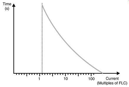
++++7. Typical fuse characteristic.
By nature, fuses can only detect faults associated with excess current. Therefore, a fuse will only blow in ground fault conditions once the current in the faulty phase has increased beyond the overcurrent value. Therefore, fuses don’t offer adequate ground fault protection. A fuse has only a single time-current characteristic, and cannot be adjusted. In addition, fuses need to be replaced after every operation. Finally, fuses cannot be given an external command to trip.
Fuses are inexpensive. Therefore, they are suitable to use solely on less critical circuits, in conjunction with contactors or as back-up protection should the main protection fail.
They offer very reliable current-limiting features by nature.
Another advantage of fuses is the fact that they can operate totally independently, i.e. they don’t need a relay with instrument transformers to tell them when to blow. This makes them especially suitable in applications like remote Ring Main Units, etc.
Is-limiter
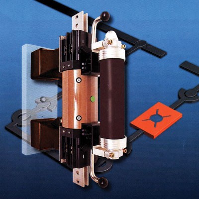
A very "special" type of fuse is the Is-limiter, originally developed by ABB. The device consists of two main current-conducting parts, namely the main conductor and the fuse.
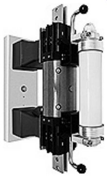
++++8. Construction of Is-limiter
The device functions as an 'intelligent fuse'. The functional parts are the following:
• Current transformer (detects the short-circuit current)
• Measuring and tripping device (measures the current and provides the triggering energy)
• Pulse transformer (converts the tripping pulse to busbar potential)
• Insert holder with insert (conducts the operating current and limits the short circuit current).
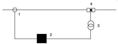
++++9. Functional diagram of Is -limiter
The IS-limiter is intended to interrupt very high short-circuit currents very quickly, in order to protect the system against these high currents. Currents of up to 210 kA (11 kV) can be interrupted in 1 ms. This means that the fault current is interrupted very early in the first cycle.
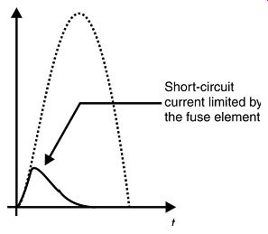
++++10. Fault current cycle
When a fault current is detected, the main conductor is opened very swiftly. The current then flows through the fuse, which interrupts the fault current. The overvoltage occurring due to the interruption of current is relatively low due to the fact that the magnitude of current on the instant of interruption is still relatively low. The main conductor and parallel fuse have to be replaced after each operation. The IS-limiter is only intended to interrupt high fault currents, leaving the lower fault currents to be interrupted by the circuit breakers in the system. This is achieved by the measuring device detecting the instantaneous current level and the rate of current rise. The rate of current rise (di/dt) is high with high fault currents, and lower with lower fault currents. The IS-limiter only trips when both set response values are reached. A practical use of the IS-limiter, where the combined fault current supplied by two transformers in parallel would be too high for the switchgear panel to withstand.
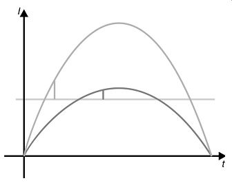
++++11. Rate of current rise.
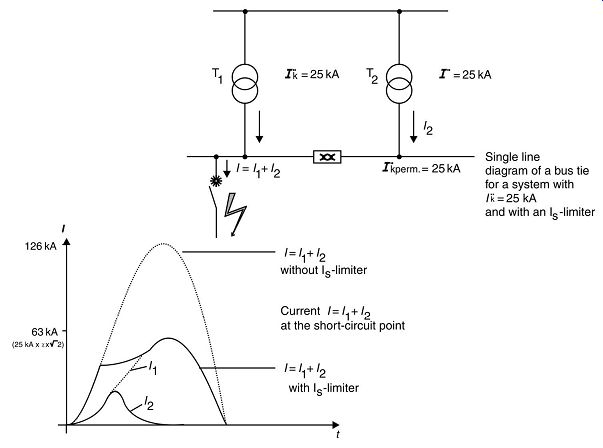
++++12. Practical use of I_s-limiter.
| Top of Page | PREV: Medium-voltage switchgear--part 1 | NEXT: Medium-voltage switchgear--part 3 | Index |