Insulation methods
Oil circuit breakers:
In this design, the main contacts of the circuit breaker are immersed in oil.
Oil in CB has two functions--i.e. cooling the arc and providing insulation of the live parts.
The energy inherent in the electrical arc has the effect of decomposing the switch oil into four component parts:
1. 70% hydrogen
2. 22% acetylene
3. 5% methane
4. 3% ethylene.
Due to this decomposition into gas components, the arc effectively lives in a bubble of gases, this being surrounded by the oil.
The formation of gas and carbon during arcing reduces the insulation properties of the oils. This requires the oil to be charged on a regular basis.
Oil has the following advantages:
• Ability of cool oil to flow into the space after current zero and therefore extinguishing the filament arc that is still in existence
• A cooling surface is presented by oil to the contact surfaces
• Absorption of arc-energy by decomposition of oil from liquid to gas
• Oil acts as an additional insulator lending to more compact designs of switchgear.
Disadvantages:
• Inflammability, especially if there is any O2 near the generated gasses
• Additional maintenance is required to ensure that the oil is kept in a suitable and adequate operational state
• Additional fire and environmental hazard with possible leakage of oil out of switchgear.
AMAZON multi-meters discounts AMAZON oscilloscope discountsOil circuit breakers are not manufactured on a large scale anymore by the world's leading switchgear manufacturers. This is mainly due to the major disadvantages as mentioned above, namely fire and environmental hazard, and high maintenance requirements.

Air break switchgear:
Air break switchgear can be divided into two major divisions, namely air circuit breakers (ACBs), mainly utilized for low-voltage applications, and high-voltage air disconnectors and breakers utilized in high-voltage switchyards. The latter falls outside the scope of this manual. The ACB is discussed briefly.

Air circuit breaker (ACB):

The interrupting contacts are situated in free air, and as such use this medium for arc suppression and cooling. The ACB normally uses an electronic tripping device, as an integral part of the equipment, to provide the tripping signal.
AMAZON multi-meters discounts AMAZON oscilloscope discountsThe resultant arc is chopped into a number of smaller arcs by the arc-chute as it rises due to the generated heat and associated magnetic forces. In some cases air puffers are used to aid the upward movement of the arc. In other cases air under high pressure is used to 'blast' the arc away. This type of breaker is relatively large, due to the distance needed between phases with only air as insulating medium. New air breakers are very seldom used for voltages exceeding 3.3 kV nowadays.

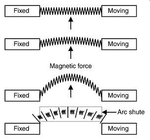
++++13. Illustration of ACB contacts
The following are the advantages and disadvantages of air breakers.
Advantages:
• Economical choice for voltages up to 1000 V
• Simple construction
• No fire or health hazard
• "Soft" break of current, due to the fact that the ionization of air will support current flow during the early stages of contact separation
• High short-circuit withstand and breaking capability.
Disadvantages:
• Not economical for voltages exceeding 3.3 kV (too big)
• Requires regular maintenance in mV application's.
Sulphur-hexaflouride (SF6)
Sulphur-hexaflouride (SF6) is an inert insulating gas that is becoming more and more popular in modern switchgear designs both as an insulating as well as an arc-quenching medium.
The pressure of the SF6 gas is generally maintained at a pressure between 2 and 10 bar.
So good sealing of the gas chambers is vitally important. Leaks will cause loss of insulating medium and it has to be remembered that contact clearances are not designed for operation in air. Certain types of switchgear are rated to be able to break normal load current in the absence of SF6, i.e. with only air as insulating medium, but not fault current. Opening of the contacts in air under short-circuit conditions will have catastrophic consequences.
The SF6 switchgear can have the facility to continuously monitor the gas pressure in the contact chambers. Modern relays have the capability to automatically raise an alarm the instant this pressure falls below a specified limit, trip or lock-out the CB in its current position when a second predefined pressure limit has been reached, and/or continuously send through gas pressure information to a SCADA control station. Even though the risk of gas leaks is very low with modern switchgear, the monitoring of SF6 gas pressure is strongly recommended, either automatically or as part of a manual maintenance procedure.
Practical tip: A common concern regarding the use of SF6 gas pressure monitors are that the monitor itself posses the highest risk of causing a leakage. This very seldom occurs when switchgear is manufactured under tight quality control measures, as it should be.
However, it can be seen as an additional point of risk. But even if a gas leakage develops at the pressure monitor, at least an alarm will be raised, and the responsible personnel will know about it, and corrective measures can be taken in advance.
With no monitor installed, no one will know about a gas leakage until it’s too late, with possible disastrous consequences. Therefore, having pressure monitors on the switchgear can be regarded as the lesser of two evils by far.
SF6 gas: SF6 gas is an inert gas, colorless and odorless. It’s not poisonous or flammable. It’s heavier than air, hence in case of a leakage, SF6 gas will collect in the lowest regions of the substation, which are normally the cable trenches, and replace all the air. Therefore, it may pose a health risk to human beings in that it may cause suffocation to unaware workers.
How would you prevent a possible build-up of SF6 gas when using SF6 type switchgear?
GIS switchgear:
Gas-Insulated switchgear (GIS) also uses SF6 gas to insulate not only the switch contacts, but most of the switchgear panel, including the busbars. The GIS has been used at the higher-voltage levels, namely 66 kV and above, but is also becoming a viable option for medium-voltage applications in special circumstances. The switchgear manufacturers ABB, for example, has used this technology very successfully in designing efficient, compact and safe Ring Main Units.
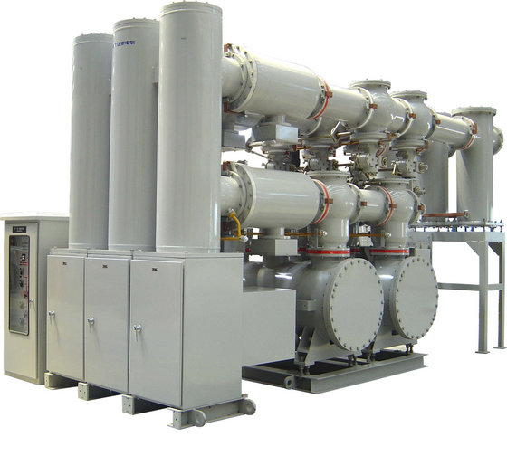
The main advantage of GIS is the reduced clearance distances required due to the superior insulating properties of SF6 gas, resulting in compact, space-saving switchgear.
Therefore, the higher the voltage level, the more the space-saving benefits obtained.

The following are the advantages and disadvantages of SF6.
Advantages:
• 'Softer' switching than, for example, vacuum breakers, meaning that less pronounced voltage peaks are caused when interrupting large currents
• Suitable for voltages up to 66 kV for metal-clad switchgear and 800 kV for GIS
• SF6 gas pressure can be easily monitored
• Insulating medium present no fire/explosion hazard.
Disadvantages:
• Depositories formed during switching limit the number of achievable operations before maintenance/refurbishment is required
• More expensive than other types of switchgear
• Decomposed SF6 products are toxic and should be handled with care.
Vacuum breakers:
Vacuum switchgear applies the principle that it’s virtually impossible for electrical current to flow in a vacuum. Therefore, the main contacts separate inside a vacuum bottle.
The typical contact material comprises a tungsten matrix impregnated with a copper and antimony alloy to provide a low melting point material to ensure continuation of the arc until nearly current zero.
The early designs of vacuum breakers displayed the phenomenon of current chopping i.e. switching off the current at a point on the cycle other than current zero. This sudden instantaneous collapse of the current generated extremely high-voltage spikes and surges into the system, causing failure of equipment (Remember the formula V = L di/dt ?). Another phenomenon was prestrike at switch on. Due to their superior rate of dielectric recovery, a characteristic of all vacuum switches was the production of a train of pulses during the closing operation. Although of modest magnitude, the high rate of rise of voltage in prestrike transients can, under certain conditions, produce high insulation stresses in motor line end coils.
Subsequent developments attempted to alleviate these shortcomings by the use of 'softer' contact materials, in order to maintain metal vapor in the arc plasma so that current continues to flow until point zero. Unfortunately, this led to many instances of contacts welding on closing.
Re-strike transients produced under conditions of stalled motor switch-off were also a problem in vacuum contactors. When switching off a stalled induction motor, or one rotating at only a fraction of synchronous speed, there is little or no machine back emf, and a high voltage appears across the gap of the contactor immediately after extinction. If at this point in time the gap is very small, there is the change that the gap will break down and initiate a re-strike transient, puncturing the motor's insulation.
Modern designs have all but overcome these problems. In vacuum contactors higher operating speeds coupled with switch contact material have chosen to ensure high gap breakdown strength, produce significantly shorter trains of pulses.
In vacuum circuit breakers, operating speeds are also much higher which, together with contact materials that ensure high dielectric strength at a small gap, have ensured that prestrike transients have ceased to become a significant phenomenon.
However, by nature of their design, vacuum switchgear do cause higher-voltage peaks when breaking high currents, compared to other types of switchgear. With the use of special surge arrestors and wave-slowing capacitors, the transient overvoltages can be prevented from damaging the motor's insulation.
The following are the advantages and disadvantages of vacuum switchgear.
Advantages:
• Due to virtually no depositories being formed during the breaking operation, vacuum switchgear support a large number of operations
• More compact than the other types
• Vacuum bottles are relatively inexpensive and easy to replace
• Very little maintenance needed.
Disadvantages:
• Tendency to cause voltage 'spikes' when interrupting large currents
• No practical method available at this stage to monitor the vacuum inside the bottle
• Generally limited to voltages of up to 36 kV.-- the typical construction of a vacuum circuit breaker.
===
Comparison of insulating methods for CBs
Property Air Oil SF6 Vacuum
Number of operations Medium Low Medium High
'Soft' break ability; Good; Good; Good; Fair
Monitoring of medium N/A Manual test Automatic Not possible
Fire hazard risk None High--None--None
Health hazard risk None Low--Low None
Economical voltage range Up to 1 kV 3.3-400 kV 3.3-800 kV 3.3-36 kV
===
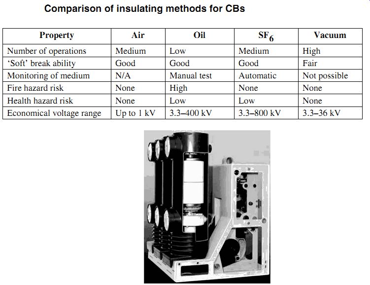
++++14. Typical vacuum circuit breaker
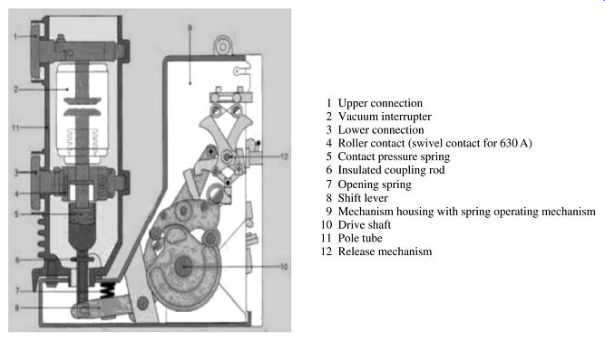
++++15. Internal construction of a vacuum circuit breaker
Types of closing mechanisms
Hand operated:
A cheap version but is losing popularity as the operating speed depends entirely on the operator's dexterity. Additionally it’s only used at ratings of 150 MVA and less, and up to a maximum of 11 kV.
Hand operated and spring assisted:
Hand actuator compresses a cam-spring arrangement over top dead center (>90°). The spring is under compression and, once past T.D.C, completes the cycle to 180° and closes the breaker.
Quick make:
A variance on the device described in version (2) above. A spring is compressed and latched by a hand-operated system. The spring is then released by operation of the latch to operate mechanism.
Motor wound spring:
Versions (2) and (3) above can have a motor replacing the manual function as described.
Motor-driven systems have gearboxes, and are used for larger systems (high MVA ratings).
Solenoid:
Versions (2) and (3) above can have a solenoid replacing the manual function as described; this is more common on the smaller ranges of switchgear.
Pneumatic:
Used at 69 kV and above. Convenient, but a supply of dry air is required.
Hydraulic:
Hydraulic pressure is increasingly being used on modern circuit breakers.
| Top of Page | PREV: Medium-voltage switchgear--part 2 | NEXT: Medium-voltage switchgear--part 4 | Index |