
AMAZON multi-meters discounts AMAZON oscilloscope discounts
When selecting a cable for your specific application, a number of variables require attention. These are:
- • Application
- • Size and type of load to be supplied
- • Permissible voltage drop
- • Prospective fault current
- • Circuit protection
- • Installation conditions
Application:
Low-voltage distribution:
For LV distribution purposes, the choice is basically between XLPE and PVC-insulated cables. The XLPE cables have higher current ratings than PVC cables for the same conductor size. Normally XLPE cables tend to be slightly more expensive than PVC cables.
AMAZON multi-meters discounts AMAZON oscilloscope discountsThe choice between these two types for LV applications will normally be determined by economic considerations (the relative prices at that stage) and availability. Bear in mind that a slightly smaller XLPE cable can be chosen for the same current requirement, which have other spin-offs, for example space-saving on cable racks or in trenches, slightly reduced labor costs for installation, etc.
AMAZON multi-meters discounts AMAZON oscilloscope discountsMedium-voltage distribution:
For MV applications, the choice is more involved. First of all, the choice lies between overhead lines and underground cables. Nowadays, the tendency is to move toward underground cables for distribution purposes, the motivation mainly being the following:
• Distribution is mainly done in industrial and/or populated areas, where overhead lines pose an environmental hazard.
• Overhead lines are very maintenance intensive, due to required protection against corrosion, pollution and fires.
• Overhead lines are very susceptible to lightning strikes.
Due to the above considerations, overhead lines are mainly considered for applications over relatively large distances, where they are very economic compared to underground cables. The next choice is then between aluminum or copper conductors. Aluminum conductors are larger than copper conductors for the same current-carrying capacity, which may add to installation costs. The choice will mainly be an economic one, influenced by availability and the relative prices of the two metals at that stage. Aluminum conductors may be considered in high corrosive areas.
The third choice is the question of cable insulation type. For normal distribution purposes, the choice lies between PILC- or XLPE-insulated cables. The choice will be influenced by taking the following factors into account:
• PILC cables tend to be more expensive than XLPE cables for the same conductor size.
• XLPE cables have a higher current rating for the same conductor size.
• XLPE cables have a larger overall diameter for the same conductor size.
• PILC cables provide better corrosion resistance than XLPE cables.
• PILC cables have a higher average life span, 40 years compared to 25 years of XLPE cables.
• XLPE cables are better suited to be moved frequently after installation, making them better suited for use in an continuously changing environment, for example mining applications.
Single-core cables may also offer an economical choice, especially in high-current applications, where the installation of three single-core cables (one per phase) might be preferred to the option of installing a number of 3-core cables in parallel. The outer 'PVC' sheath is available in finishes, e.g:
• No stripe - plain PVC
• Red stripe - fire retardant
• Blue stripe - low halogen
• White stripe - zero halogen
All 'PVC' covering are also UV resistant. Once a choice is made, companies tend to stick to a specific type of cable, in order to prevent confusion, eliminate the need for re-training of personnel, and reduce stock levels.
Load to be supplied In order to select the appropriate cable, it’s necessary to know the voltage and the load current, as the first step in the selection process.
The following formulae apply:
FL kW 1000:
- if we know kW, voltage, and power factor 3 cos kVA 1000
- if we know the kVA rating and voltage
Use this value of current to determine the cable size by reference to the relevant manufacturer's tables for copper or aluminum conductors.
A slightly larger conductor size may be chosen for safety aspects, and to provide for the higher than usual current, which may be experienced during starting of electric motors.
Example of cable selection for low voltage (Note: The tables used in this manual are for illustrative purposes only. They are based on data supplied by the cable manufacturer ABB Power Cables. The user should use the corresponding tables supplied by the specific manufacturer of the cable he is using, as each manufacturer's specifications will vary.) Suppose it’s required to supply a three phase, 400 V, l00 kW motor, over a distance of 50 m, the motor load is known to have a power factor of 0.9 lagging. The full load line current, IFL can be calculated as follows:
Full load current ratings can usually be obtained easily from the equipment nameplate.
We now refer to ==== (example table for LV cables) and note that the smallest copper conductor, PVC-insulated cable, that can supply a current of 161A in air, is a 50 mm^2 rated area cable. This cable can carry 167A continuously if installed under standard conditions.
Permissible voltage drop:
Calculate the highest current drawn by the load, by multiplying the current as calculated by an appropriate factor. If a Star/Delta motor starter is used on a motor, this factor is 3. If the motor is started direct on line, then use a factor of 6. A factor of 2 may be used for most electronic soft-starters. Where the load is resistive heating, lighting or a transformer, it’s not necessary to increase the current as calculated. Calculate the volt drop that will be experienced at the load terminals. The maximum volt drop allowed by the Standard for Electrical Installations (Standard; known as Wiring Rules) is 5%. The volt drop may be calculated in two different ways:
1. Multiplying the current by the impedance of the length of cable. Calculate the percentage volt drop by reference to the phase-to-ground voltage.
2. Multiply the current by the length of cable, and then multiply the result by the volt drop per amp per meter.
Previous example using method (a)
Starting current 3 running current
Impedance of 50 m of 50 mm cable =
Previous example using method (b)
Starting current
Volt drop per amp per meter
Volt drop
Percentage volt drop
Note: It often happens on long runs of electric cable that a larger conductor than that calculated is required for volt drop reasons.
It must be noted that the calculation as per the above example is an approximation.
However, it’s accurate enough for cable selection purposes. (In fact, it’s accurate enough for most practical purposes.)
Why is the method as illustrated above only an approximation? What is the correct method to calculate the exact volt drop?
Example of cable selection for MV (5-33 kV)
We wish to supply a 2 MVA 11 kV transformer from a utility supply which is 3 km away.
Underground paper-insulated, copper conductor cable is to be used.
The depth of burial of the cable is 1.25 m. Ground thermal resistance is 2 Km/W. The ground temperature is 25 °C and there are no other cables in the trench.
Short-circuit level may be assumed to be 250 MVA, and the ground fault level 100 MVA, and it may be assumed that a fault will be cleared in half a second.
Using the previous formulae:
105 A before derating for non-standard conditions =
De-rating factor for depth of burial at 1.25 m is 0.96. De-rating factor for soil thermal resistivity at 2 Km/W is 0.84. De-rating factor for ground temperature of 25 °C is 1.00.
====27 shows that a 35 mm^2 copper conductor cable would be capable of carrying this load (130A).
Checking for volt drop:
Volt drop is seldom a problem at MV, even for long runs of small conductor size as shown above.
Why would volt drop seldom be a problem at higher voltages?
Prospective fault current:
Electric cables are designed to operate below a certain maximum temperature, this being dependent on the conductor material and the type and the thickness of the insulation.
Cable selection for a particular installation must therefore be made on the basis of not exceeding these temperature limits.
Suppose the 400 V distribution board from which a cable is fed has a fault level of 5 MVA. This translates to a fault current of 7.22 kA, and the cable must be capable of carrying this current without damage until the fault is cleared. Fault current ratings for cables are given in the manufacturers' specifications and tables and must be modified by taking into account the fault duration.
The smallest cable that can safely handle the above fault current for a 1 s fault, is a 70 mm^2 copper conductor cable, or a 95 mm^2 aluminum conductor cable. Suppose now that the fault clearance time (including any mechanical delays on the tripping mechanism) is closer to 2 s, then the smallest cable would be a 95 mm^2 copper conductor (11.52/v2 = 8.13 kA for 2 s) or a 150 mm^2 aluminum conductor (10.80/v2 = 7.64 kA for 2 s). Likewise, a fault duration less than 1 s will allow the use of smaller conductors than were calculated for the 1 s rating.
Continuing with the example: Prospective symmetrical (short-circuit) current:
Cable short-circuit current withstand is:
K is 115 for copper conductors, paper insulated The half second rating is thus:
This cable won’t survive the prospective short-circuit current. Conductor size required is thus:
The nearest standard size is a 95 mm^2 copper conductor. This has a current rating of 235 A under standard conditions.
Ground fault current for half a second Lead area for a 95 mm^2 × 3-core PILC cable is 198.2 mm^2
Cable ground fault current withstand is =
Required ground fault current, =
= 5.25 kA for half a second
In many cases, the cable conductor size is larger than dictated by the full load current, and is chosen in order to survive the prospective short-circuit current.
The use of large conductors can be avoided by improving the speed of protection (fuses For example) and in the case of ground fault current, by the use of sensitive ground fault protection.
Another example is shown.
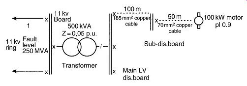
++++ 1. Distribution example We’re required to calculate the fault current
at the sub-distribution board.
P.U. system: Base MVA p.u. source impedance--Fault level MVA = (1)
Base MVA transformers % impedance p.u. transformer impedance -- Transformers MVA (ohms) -- Base MVA p.u. cable impedance (kV)
p.u. total impedance (1) + (2) + (3) = Base MVA Fault level p.u. impedance Fault level (MVA) 1000000 Fault current 3 V
Example 1 Using a base of 100 MVA and the per unit method, the impedance of the system at the sub-dist board can be determined:
Source: = 0.4 p.u.
Transformer: 0.05 = 10 p.u.
From ====25, the impedance of 185 mm^2 cable = 0.1445 ohm/km. Thus the impedance of 100 m = 0.01445 ?
The fault level at the sub-dist board is then found by dividing the base MVA by the total per unit impedance.
Fault level at sub board = Fault current at sub-dist. -- Board =
Will a different answer be obtained if a different base value is obtained? Prove your answer by repeating the above example for a base value of 250 MVA. Where: 115 for PVC/copper cables of 1000 V rating 143 for XLPE/copper cables of 1000 V rating 76 for PVC/aluminum (solid or stranded) cables of 1000 V rating 92 for XLPE/aluminum (solid or stranded) cab = les of 1000 and where: the conductor cross-sectional area in mm the duration of the fault in seconds
So in our example:
Reference to ====25 shows that a 70 mm^2 copper cable can withstand a short-circuit current of 8.05 kA for 1 s. This is below the potential fault level of the system. However, the duration of the fault or the time taken by the protective device to operate has to be considered. The circuit supplying the motor would very likely be protected by a 200 A fuse or a circuit breaker. Both these devices would operate well within 1 s, the actual time being read from the curves showing short-circuit current/tripping time relationships supplied by the protective equipment manufacturer. Suppose the fault is cleared after 0.2 s. We need to determine what short-circuit current the cable can withstand for this time. This can be found from the expression:
This is well in excess of the system potential fault level and below the bursting capacity of the cable so it can be concluded that a 70 mm^2 cable is suitable for this example.
Bursting is not a real threat in the majority of cases where armored cable is used since the armoring gives a measure of reinforcement. However, with larger sizes, in excess of 300 mm^2 , particularly when these cables are unarmored, cognizance should be taken of possible bursting effects.
When the short-circuit current rating for a certain time is known, the formula E = I^2 t can also be used to obtain the current rating for a different time. In the above example:
Note: In electrical protection, engineers usually cater for failure of the primary protective device by providing back-up protection. It makes for good engineering practice to use the tripping time of the back-up device, which should only be slightly longer than that of the primary device in short-circuit conditions, to determine the short-circuit rating of the cable. This then has a built-in safety margin.
Environmental conditions of installation:
The data used for determining the current ratings given in this manual are based on calculations according to IEC 287. Ratings for multicore cables are given for a single cable run; where groups of cables run in a common route, the appropriate derating factors are given in the appropriate sections depending on the type of cable being used.
Similarly when the installation conditions differ from standard, the derating factors in the appropriate sections must be used.
A qualitative assessment of the conditions immediately surrounding the cable should be made. Factors such as the need for a fire-retardant sheath, additional mechanical protection, safeguards against chemical attack and corrosion should be considered in this category. These influences affect mainly the external finish of the cable, the armoring and serving.
Cables are sometimes specified with a termite-repellent sheath. It’s worth mentioning that no sheath will repel insects since sheath material has to be ingested by the termite to be fatal. Thus, the statement 'cable with a termite repellent sheath' is somewhat erroneous. The PVC sheath is coated with Teflon that makes it difficult bite into the PVC.
In the case of paper, lead cables there are several alternative sheath metals available, pure lead is prone to fatigue when subjected to vibration. An alloy sheath can be supplied which will resist deterioration through fatigue.
The foregoing notes are by no means an exhaustive treatment of the points to consider when choosing a cable for a particular application but are rather guidelines to the salient points that need consideration.
Cables laid directly in the ground:
The ratings given are based on a ground thermal resistivity (g) of 1.2 Km/W. The factor (g) varies considerably with differing ground conditions and has a pronounced effect on a cable's current-carrying capacity. The only sure way to determine (g) is to measure it along the cable route. This practice is normally reserved for super-tension cables, but there could be other applications where soil thermal resistivity is critical.
Suitability of soils for bedding and backfill:
Clay:
Clay is a dense, compact material, greasy to the touch when wet and which has a low thermal resistivity even in the fully dried-out condition. Most types of clay however, shrink when drying and can thus not be used as a bedding for the cable. They can be used as backfill and should be consolidated by rolling rather than stamping.
Sand:
Sand is a crumbly material with particle grains easily distinguished and gritty to the touch even when wet. Particle sizes larger than 2 mm are known as gravel. Sea sand or sand obtained from a river bed usually consists of spherical particles and has a very high thermal resistivity when dry. Therefore, it should not be used as cable bedding in its pure form. Some quarried sands and man-made sands as used for making concrete, have irregularly shaped particles of varying size and can be compacted to a high density. These can be used as a bedding material especially when 5-10% clay is added and will have a satisfactorily low thermal resistivity in the dried-out state. Sand/gravel mixes should be used with care as sharp particles can damage the cable serving.
Sand Clay--Sand clay is, as its name implies, a mixture of sand and clay. It’s an ideal material for use as bedding and backfill and is best compacted by rolling. It rarely dries out to lower than 6% moisture content.
Loam:
Loam can vary in color from reddish brown to dark brown and may contain quantities of organic matter. It crumbles well, even when dry, and can be well compacted to achieve satisfactory values of thermal resistivity. It’s very suitable as a bedding material.
Chalk:
Chalk is a soft white or gray porous material having a lower thermal resistivity when wet, but dry out to very high values and is unsuitable for use as bedding or backfill in any area where drying out is likely.
Peat:
Peat or humus is composed mainly of organic material and is black or dark brown in color. It should not be used as bedding or backfill as dried-out thermal resistivity values of over 4 Km/W are usually obtained. It should be removed and alternative material used for both bedding the cables and backfilling the trench.
Make-up soil This is a general term for the soil in any area, the level of which has been raised artificially using imported fill which may consist of bricks, concrete, cinders, ash, slag, stones, other refuse or any of the material considered above. This should only be used for backfill and never for cable bedding. If any doubt exists as to suitability, it’s best removed completely and a suitable material imported.
Mine sand:
Mine sand is thermally very satisfactory, but is highly corrosive and should therefore not be used.
The thermal resistivity of a substance is greatly influenced by the moisture content at a given time. The higher the quantity of retained moisture, the lower will be the thermal resistivity. A heavily loaded cable will dry out the soil around the cable and cause an increase in (g). This process is cumulative and damage could be done to the cable insulation through overheating.
Table of: Typical values of thermal resistivity of substances encountered in cable installations Impurities such as slag, ash and the like increase the value of (g), as does intense vegetation on the cable route, by drawing moisture from the ground.
Cables installed in air:
Multicore cables should be installed with a space of >0, 3 × overall diameter and single core cables with a space of >0, 5 × overall diameter between themselves and the vertical wall or surface supporting them as per IEC 287. If they are installed in direct contact with the wall then the current rating given should be reduced by 5% as a rough guideline provided there is a space of 150 mm or six times the overall diameter of the cable, whichever is the greater between adjacent cables or cable groups in the case of single core cables. If the installation fails to comply with this requirement then the derating factors in the relevant sections should be applied.
Where the ambient temperature along a route varies, the highest value should be taken to select the cable size.
Why should cables be de-rated when they are installed close to each other or against a wall?
Cables installed in ducts:
The air within a pipe or duct will increase the thermal resistance of the heat dissipation path. Consequently, the current rating for a cable run in a duct or pipe is lower than that for an equivalent cable in the ground or in free air. The ratings given can be applied to cables laid in concrete, asbestos, pitch fiber, PVC, earthenware or cast iron pipes which are the more common materials encountered. It should be noted that single-core cables forming a part of an AC system should not be individually installed in cast iron pipes due to the heavy losses incurred by eddy current induction.
Generally, the size of the duct or pipe chosen should depend upon the ease of pulling in, or out, the cable. It should be borne in mind that a larger cable may be required in the future to cater for increased load growth. Common pipe sizes used are 100 mm and 150 mm internal diameters. When groups of cables are run in pipes along the same route, they should be de-rated according to the factors given in the relevant tables.
Composite cable routes:
It frequently happens that a cable run is made partly in air, partly direct in the ground and partly in ducts. The latter conditions lead to the lowest rating and it’s here that attention must be focused. Very little heat travels longitudinally along the cable, the main dissipation being vertically through the duct wall and surrounding ground. Any rating where the route is part ground, part duct must therefore be treated with care.
Where the length of ducting does not exceed 5m per 100m of route length, the cable rating may be assumed to be that for direct burial in the ground.
Intermittent operation:
Certain types of loads have an intermittent characteristic where the load is switched on and off before the cable has time to cool completely. Depending upon the load cycle it may be possible to select a smaller cable for intermittent operation than would be the case if the load were continuously applied. When a current in excess of the normal rated current is applied, the heating of the cable will be a correspondingly quicker operation than the cooling.
Generally:
I = Equivalent RMS current
In = Current flowing during nth period (including periods of zero current)
tn = Duration of nth period
N = Number of periods, (includes periods of zero current)
Thus:
Example: Suppose a process cycle is as follows: 150 A for 1 min 50 A for 2 min 100 A for 3 min, 0 A for 4 min then applying the expression for RMS current (57 500/10) 75.83A
Thus a continuous current of 76 A flowing over the 10 min cycle time would produce the same heating effect as the individual cyclic currents, and the size of cable could be selected based on 76 A.
Solar heating:
When cables are installed in direct sunlight, an appreciable heating due to solar absorption takes place. This result in a significant reduction in the cables' current carrying capacity and for this reason it’s strongly recommended that cables be protected from direct sunlight. The maximum intensity of solar radiation measured varies between 100 and 115 mW/cm^2 depending upon location.
| Top of Page | PREV: MV Power cables -- part 1 | NEXT: Transport, handling and installation of electric cables | Index |