
AMAZON multi-meters discounts AMAZON oscilloscope discounts
Cables on wooden drums:
• The cable drum is manufactured from carefully selected wood with a low moisture content (typical not more than 15%). If they are required to be treated it shall be done with a preservative or with chromate copper arsenate. Certain types of hardwood don’t require treatment.
• Marking on drum flanges should be clear, stenciled or burned into the wood and should include the following information (this will depend on the specific manufacturer, but may be requested by the client):
- Manufacturer's name or trademark
- Rated voltage, rated area, number of cores and specification
- Length of the cable in meters / feet
- Year of manufacture
- Gross mass in kilograms
- The instruction 'not to be laid flat'
- Serial number or other identification
- On each flange an arrow with the words 'roll this way'
- The standard to which the cable is manufactured.
• Both ends of the cable on the drum should be sealed and the inner end fixed to the flange of the cable drum to prevent loose coiling. The outer end is fixed to the flange as well, for the same reason.
• Cable drums should stand on firm, well-drained surfaces.
• In the past, it was common practice to rotate stored cable drums through 180° to redistribute the impregnation oil through the dielectric. The use of MIND cables has obviated this reason for rotating drums. However, it’s still recommended that wooden cable drums that are stored in the open, irrespective of the type of cable contained, should be periodically rotated to avoid the drum timber rotting through rising damp.
AMAZON multi-meters discounts AMAZON oscilloscope discountsCable transportation
Preparation:
• The truck must match the drum size
• Don’t overload the trucks
• Cable ends must be sealed, secured and protected
• Use special cable trailers for transportation from depot to site if possible.
++++2. Cable trailer
Loading:
• Check drums for correct cable and size, serial number, mass and possible damage
• Select correct forklift/crane
• Select correct slings and spindle and check sling condition
• If a crane is to be used, ensure that a spreader is incorporated to prevent damage to drum flanges
• If the drum is to be rolled, observe correct rolling direction by referring to arrows on flanges
• Ensure that the drum bolts are tight
• Ensure that truck surface is clear of obstructions, nails, etc.
• Don’t drop drums onto truck loading bed.
Securing:
• Secure drums to the truck bed to prevent sliding and rolling, using adequate steel chains and chocks
• Always try to pack drums flange-to-flange
• Don’t lay drums flat
• Stop the vehicle during transportation and check that the load is secure.
Off-loading:
• Check for damage to cable drums
• Select correct spindle slings for the drum size and mass and ensure that same are in good order, ensure that a spreader is used
• Don’t drop drums but lower gently onto firm and relatively level surfaces
• Off-load drums in such a way that they are easily accessible
• If using a fork-truck, ensure that it’s of adequate size relative to the task at hand
• Ensure that the fork-truck tines lateral spacing is correct
• Take care that the protruding tines don’t damage other equipment or drums
• There are two methods of rolling drums from loading beds if cranes are not available.
AMAZON multi-meters discounts AMAZON oscilloscope discounts 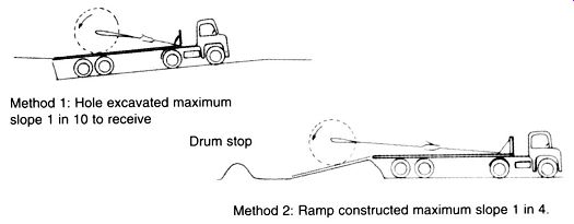
++++3. Unloading cable drums
Cable storage:
Indoors:
• Stack flange-to-flange and preferably not one on top of the other
• Stack so that drums are easily accessible
• Observe fire prevention rules
• Cable ends must be sealed at all times
• Dispatch on 'first in-first out' basis
• Rotate paper-insulated cable drums one complete revolution per annum.
Outdoors:
• Drums should be stored on a hard surface at a slight angle and the area should have a drainage system
• Drums should be released on a 'first in-first out' basis
• Cable ends should be sealed at all times
• Stack flange-to-flange but if this is not possible, limit vertical stacking practice to smaller drums only
• Stack in such a way that drums are easily accessible
• Observe fire protection rules
• Cable racks are ideal for storage but take care not to overload
• Cables must be identifiable at all times
• If drums are expected to be stored for a long time they must be specially treated or made of hard wood
• Rotate paper-insulated cable drums one complete revolution per annum.
Mechanical forces on cables during installation:
Any cable has a maximum pulling force, which should not be exceeded during installation.
The cable construction imposes the limitation on the pulling-in force. When a cable stocking is used, the maximum force can be related to overall cable diameter in mm as follows: Steel wire armored cables: F = 0.94 d4 × 10^-6 kN
Steel tape armored or unarmored cable: F = 0.39 d4 × 10^-6 kN
Control and communication cables: F = 0.26 d4 × 10^-6 kN
Attempts should be made to limit the pulling force required to a minimum to avoid stretching the outer layers of the cable. This is particularly relevant where control and communication cables are concerned since instances are known where the cores have finished 2-3 m inside the sheath and insufficient overlap at straight joint positions has necessitated relaying some lengths.
An increase in the pulling force is permissible when the cable is laid by means of a pulling eye attached to the conductors. As a rule of thumb, the following forces may be applied to a conductor:
Copper: 4.9 × 10⁻² kN/mm^2
Aluminum: 2.94 × 10⁻² kN/mm^2
Then, for example the maximum force that should be applied via a pulling eye to a 70 mm^2 , 3-core copper cable is:
Generally when cables are installed using well-oiled rollers and jacks, the following forces can be expected: Straight route: 15-20% of cable weight 90° bends: 10-20% of cable weight per bend.
Example: Calculate whether it would be permissible to pull in a 300 m length of 6.35/11 kV, 185 mm^2 × 3 core, PILC cable with a winch in one go. The route has two 90° bends along the 300 m distance, and well-maintained cable rollers are used.
Taking the worst case initially: Cable mass = 12 290 kg/km × 0.3 km = 3 687 kg Force on cable = (0.2 × 3 687 × 9.8) + (2 × 0.2 × 3 687 × 9.8) = 21.68 kN
The maximum permissible pulling force (using a cable stocking): F = 0.39 × 47.424 × 10-6 kN = 1.97 kN
Therefore, the actual force on the cable would exceed the maximum permissible value.
This cable may be pulled in by means of a pulling eye attached to the conductors. (Prove this as an exercise.)
Cables laid in open trenches should be left slightly 'snaked' so that any longitudinal expansion or contraction can be accommodated. Similarly, when cables are installed in cleats or on hangers, a slight sag between fixing points is recommended.
Pulling cables through pipes or ducts:
When a cable is pulled through a pipe, friction between the cable serving and the pipe material increases the longitudinal force requirements. Representative values for the coefficient of friction (m) between the more common cable servings and pipe materials are given below.
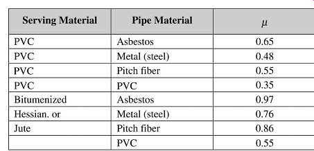
==== Friction coefficients
This information can readily be used to determine the maximum length of cable that can be pulled through a given pipe without exceeding the maximum permissible pulling force.
E.g., 70 mm^2 × 3 core cable previously quoted. If this is a low-voltage cable with a PVC sheath and it’s desired to know the maximum length of PVC pipe it can be pulled through then: Maximum force 10.29 kN (by pulling eye) = for PVC to PVC, m 0.35 = Force reactive force cable weight
--- the mass of 70 mm × 3 Core copper cable is 3.85 kg/m. Thus the maximum length of cable that can be pulled through a PVC pipe is:
If there are any bends in the route then these will create additional loading and reduce the theoretical length of cable that can be installed.
In certain instances when long runs in pipes or ducts are encountered it may be beneficial to grease the cable with petroleum jelly or some other non-aggressive compound to facilitate the pulling-in.
Considerable damage can be done to cable serving at the mouth of a pipe and precautions should be exercised at such points. This point is achieving more importance with the present day trend toward impermeable anti-corrosive sheaths which have to withstand periodic pressure tests. Included among the protective measures that can be adopted are the fitting of a rubber grommet to the mouth of the pipe and inserting a reasonable thickness of rag.
When unarmored cables are pulled into pipes it will be beneficial to ensure that there is no foreign matter present which could cause damage to the sheath before pulling. Pushing a draw rod through the pipe will usually clear any obstruction.
Preparation for cable laying:
Planning:
When planning a cable route there are several factors to be considered, among the most important of these are:
• Ground thermal resistivity (TR) tests
• Position of joint bays
• Provision to indicate on the 'as laid' drawings, the serial or drum number of the cable installed
• The use of mass or pre-impregnated non-draining paper-insulated cables, XLPE and PVC dielectrics has all but eliminated the need for special precautions when laying cables on steep slopes in shafts.
Drum handling:
• Always use the best hoisting equipment available.
• Don’t drop drums of cable onto the ground as this not only damages the drum but will damage the cable as well (especially paper-insulated cable).
• It’s most important that a minimum of rolling of the drums on the ground be allowed and then only in the direction of the arrows painted on the flanges.
• When rolling a drum of cable, to change direction use two steel plates with grease between them, and by standing one flange on these plates the cable drum may then be swiveled in the desired direction.
• Position the drum prior to cable-pulling so that the cable is pulled from the top of the drum.
• Note that a drum of power cable can weigh up to 10 tons so make sure that adequate cable drum jacks are used, that the spindle is strong enough to hold the drum and that the jacks stand on firm ground and that they hold the spindle horizontal.
• Site the drum at the most convenient place for cable-pulling, usually at the start of a reasonably straight section near the commencement of the trench work.
• Allow for drum braking.
Ground thermal resistivity:
• This often governs the rating of a power cable buried directly, as does the temperature of the soil. Losses for cables running at the maximum temperature, at which the dielectric system can faithfully operate for a maximum life of say, 25 years, are considerable, ranging from 15 W/m for normal distribution cables.
Cable conductor temperature and the soil surrounding the cable must be able to dissipate this heat effectively or thermal instability (runway) will result. For example an XLPE-insulated 11 kV cable with conductors running at 90 °C could end up with a surface temperature of about 80 °C resulting in drying-out of the soil. Depth of burial plays an important factor here and has been set at 800 mm.
Most MV cable current ratings are calculated with ground temperatures at 25 °C at depths of burial of 800 mm. LV cables are normally buried at 500 mm. Soil thermal resistivity (the ability of the soil to conduct or dissipate heat) is standard at 1.2 Km/W.
• The actual soil thermal resistivity along the proposed route should be measured by means of an ERA needle probe, but these are outside the scope of this paper; suffice it to say that different soil compositions along the route will have different rates of heat dissipation and could result in 'hot spots'.
• To overcome this, bedding and backfill soils may have to be 'imported'.
Positioning of joint bays:
Ensure that there is sufficient working space, consider passing traffic and other obstructions. If it’s not possible to position the joint bays at standard cable length distances, remember that the cable can be ordered in specific lengths. Consider drainage for large bays and try to construct the bays prior to cable pulling to prevent any damage to the cable at a later stage.
Recording cable drum serial numbers:
Cable drum serial numbers should be recorded on 'as laid' drawings. In the unlikely event of a cable failure in the future, quoting the cable drum serial number will assist the cable manufacturer in his quality control, as this serial number is related to the manufacturing and raw material management in the factory.
Preparing for cable laying:
The following 'vital actions' must be observed prior to a cable pull:
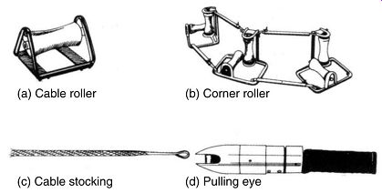
• Cable rollers must be placed between 2 and 3 m apart in the trench (depending on size of cable)
• Ensure that graphite lubricants have been applied where necessary
• Ensure that each member of the pulling gang knows exactly what he is to do and that communication signals between members are clear
• The trench floor must be clear of stones and other obstructions and the cable bedding correctly dispersed.
++++4. Cable pulling
Ensure that:
• Cable covers are available at convenient points.
• Any objects that may fall into the trench and damage the cable during the pull and prior to backfilling have been removed.
• If the ambient temperature is below 10 °C or has been so for the past 24 h, the cable on the drum will have to be covered with a tarpaulin and heated with suitable lamps or heaters for at least 24 h under close supervision. Ensure that sufficient ventilation exists, and pay the cable off the drum slowly and carefully. The drum should be lagged with only a few of the bottom lags removed during the heating process (This is necessary only for oil impregnated cables).
Why is this necessary?
• Place the drum at a convenient point prior to the pull on strong jacks and on sound footing (as mentioned earlier) with the arrow on the drum flanges pointing in the opposite direction to the rotation when the cable is being pulled.
• Before pulling, cut the inner end of the cable free.
• Remove the drum battens carefully and from the bottom.
• Inspect the cable ends for any sign of leakage (oil impregnated cables). If a leak is suspected, it can be proved by heating the cap until just too hot to touch and if insulating oil exudes out, the cap should be removed and the extent of the damage assessed, by means of a dielectric test. Cables with extruded dielectrics should be sealed and free from moisture.
• The cable must be paid off from the top of the drum, but take care not to bend it too sharply.
• Cable pulling stockings should be examined and placed over the nose of the cable with care. The pulling rope or wire must be attached to the stocking in such a way that the cable cap won’t be damaged during the pull.
• The use of swivels is recommended to prevent twisting of the stocking. The use of stockings is preferable to tying a rope directly to the cable for pulling in.
• For permissible mechanical forces see Section 3.7.
• Bending radius of cables as recommended by the manufacturer should not be exceeded.
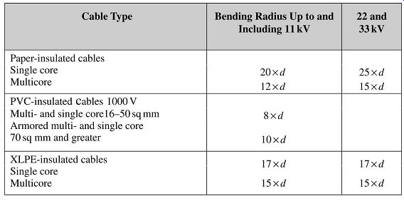
====Table 3 Recommended bending radii
• Cable should be pulled to its final position in a continuous manner.
• If a winch is being used to pull the cable and unavoidable sharp bends are encountered, a snatch block could be used to assist the pulling tension at the bend.
Once the cable pull is completed, the nose-end of the cable is carefully lifted off the rollers and placed on the bottom of the trench, leaving enough slack to terminate the cable and observing the minimum bending radius. Immediately after cutting, the cable should be suitably sealed on both ends of the cut to prevent the ingress of moisture.
Examine the nose cap and make good any damage that may have occurred during pulling.
Bond pulling:
These techniques are applied when heavy cables are to be laid or the trench undergoes many changes of direction or very long lengths of cable have to be laid, or a combination of these.
As in the previously mentioned methods of cable pulling, the trench would have been prepared with cable rollers, corner rollers and skid plates. Snatch blocks would have been anchored to the sides of the trench at bends and a winch placed at the far end of the section. At the near end a mobile bond carrier is placed conveniently adjacent to the cable drum, ensuring that its braking system is adequate and that it has rewinding facilities. A steel rope, more than twice the length of the cable to be pulled, is wound onto the bond carrier drum and its end fed over the rollers and through the snatch blocks and then secured to the drum of the winch.
The cable end is manhandled onto the first rollers and tied to the steel rope at intervals of about 2. Start the winch and as the nose of the cable arrives at the snatch block untie it from the steel cable, take it around the corner roller and retie on the straight.
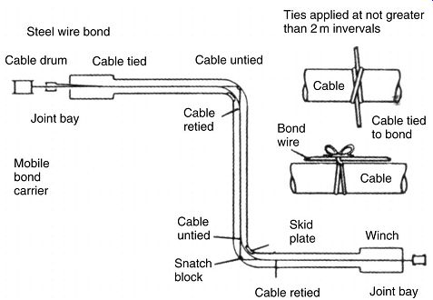
++++5. Bond pulling
Once the nose has reached the winch end, and allowing the necessary slack, the cable can be untied, the steel rope rewound onto the bond carrier. Further preparation for backfilling may then be commenced.
Backfilling and reinstatement:
Once the cables have been laid, and before commencing with backfilling carry out a visual inspection of the installation to ensure that:
• The cables are properly bedded
• Correct spacing between cables if there is more than one in the trench
• Cable entrances at ducts are suitably protected against the possibility of vermin gaining entrance
• Laying and pulling equipment has been removed
• That there is no obvious damage to cable sheaths. Up to 90% of the service failures experienced in any cable system can be avoided if appropriate action is taken at this stage.
Repairs to PVC oversheaths:
As mentioned above PVC sheaths damaged 'during pulling' should be repaired, applying the following procedures:
Superficial damage:
Generally the local area damaged should be removed, the remaining sheath chamfered for 25 mm at the edges. An EPR self-amalgamating tape is then applied after cleaning the affected area thoroughly with a suitable solvent. The PVC tape should be approximately 30 mm wide and is applied under tension with a 50% overlap continuing up the chamfer until the top is reached plus four layers extending 75 mm beyond the chamfer.
Holes or slits in the PVC sheath
Chamfer the edges of the damaged area for a distance of 30mm and abrade the area with carborundum strip for a further 20mm.
Clean the area with a solvent and apply a filling putty followed by a layer of EPR self amalgamating tape applied at high tension extending 50 mm from the patch, followed by three layers of PVC tape extending 100 mm from the edges of the EPR tape.
Removal of a complete section of oversheath Upon removal of the damaged ring, chamfer the remaining edges for a distance of 30 mm, clean with the solvent and apply four layers of EPR tape at high tension to 50 mm beyond the chamfer. Apply PVC self-adhesive tape at one-third overlap to a level corresponding to the original oversheath diameter. Five layers of PVC self-adhesive tape are then applied, each one extending 5 mm further along the cable.
The repair is then completed with a resin poultice reinforcement consisting of six layers of ribbon gage or bandage, impregnated and painted with an approved grade of freshly mixed epoxy resin. Allow 12h to cure.
| Top of Page | PREV: Cable selection | NEXT: Paper-insulated and lead-covered (PILC) 6.35/11 kV cables | Index |