
AMAZON multi-meters discounts AMAZON oscilloscope discounts
Medium-voltage XLPE-Insulated, PVC-Bedded, SWA, PVC-sheathed cables (XLPE = Cross-linked polyethylene; SWA = Steel-wired armored)

The following section generally covers 6.35/11 kV XLPE cables. For XLPE-insulated
conductors, continuous conductor temperatures of 90 °C are permissible with
overload excursions up to 130 °C for a maximum of 8 h continuous per event,
with a maximum total of 125h per annum. In the case of short circuits, the
insulation can withstand conductor temperatures of up to 250 °C for 1s. ---
the design ambient/installation conditions applicable for XLPE-insulated
6.35/11 kV cables.
Current ratings are based on these parameters:
De-rating factors for non-standard conditions:
--- show the de-rating factors to be used for calculating the current carrying capacity when these cables are used under non-standard conditions.
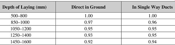
TABLE 11 Depth of laying - multicore XLPE cables (up to 300 mm^2).
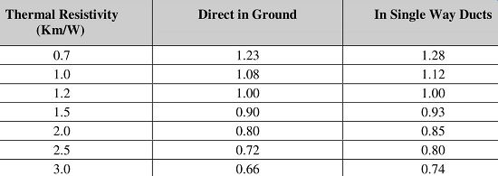
TABLE 12 Ground thermal resistivity - multicore XLPE cables (up to 300 mm^2
).
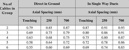
TABLE 13 Group of XLPE cables in horizontal formation at standard depths of
laying and in standard soil conditions (multicore cables).
Maximum conductor temperature: 90 °C.
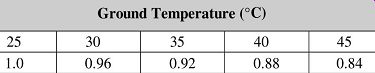
TABLE 14 Ground temperature de-rating factors Maximum conductor temperature
(90 °C)
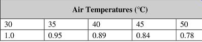
TABLE 15 Air temperature de-rating factors.
Note: Cables may be grouped in air without de-rating provided that the cables are installed on cable ladders, and that for:
• Horizontal formation: The clearance between cables is not less than 6 × the overall diameter of the largest cable (or 150 mm) whichever is the least.
• Vertical formation: The clearance from a supporting wall is greater than 20 mm, and the vertical clearance between cables is greater than 150 mm.
Note: If the number of cables >4, they are to be installed in a horizontal plane.
Short-circuit ratings for XLPE-insulated 6.35/11 kV cables Short-circuit ratings don’t lend themselves readily to rigid treatment due to unknown variables. Wherever possible conservative values should be applied. As the growth of a power system increases so do the system fault levels. When selecting a cable, attention must be given to its short-circuit capability, as well as to the continuous current rating.
AMAZON multi-meters discounts AMAZON oscilloscope discountsOther limiting effects in avoiding damage during short-circuit conditions are as follows:
• Weakening of joints due to softening of the solder at a conductor temperature of 160 °C and above, although most conductor joining nowadays is done by compression fittings, particularly on XLPE-insulated cables.
• Bucking of the conductors in joint boxes due to longitudinal expansion of cables laid directly in ground.
Cable short-circuit ratings are based on the adiabatic performance of the conductors.
This assumes no heat loss from the cable during the period of the fault. No derating factors are necessary with regard to soil temperature, depth of burial, etc.
Ratings are derived from temperature limits as follows:
Where:
= short-circuit rating in amps
= constant combining temperature limits and conductor material properties
= area of conductor
= duration of short circuit in seconds
The value of K for copper and aluminum conductors of 6.35/11 kV XLPE cables is 143 and 92 A/mm^2 respectively, for a conductor temperature rising from 90 to 250 °C TABLE provides 1 s short-circuit ratings; for other time periods the following formula should be applied.
1s short-circuit rating (kA):
Earth fault current:
Some systems provide for reducing ground fault currents by the inclusion of a neutral electromagnetic coupler (NEC) at the star point of the distribution transformer, to typically 300A.
Where this is not the case, the resistance of the copper tapes and steel wire armor should be included in the calculation.
Typical 1 s ground fault ratings for XLPE-insulated 6.35/11 kV are shown.
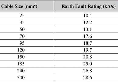
TABLE 16 ground fault ratings.
Low-voltage PVC- and XLPE-insulated 600/1000V power cables
Note on PVC insulation:
 For PVC insulation continuous conductor temperatures up to 70 °C are permissible.
Care must be exercised in matching the cable to the circuit protection. Under
short-circuit conditions, a maximum conductor temperature of 160°C is allowed
for a maximum period of 1s.
For PVC insulation continuous conductor temperatures up to 70 °C are permissible.
Care must be exercised in matching the cable to the circuit protection. Under
short-circuit conditions, a maximum conductor temperature of 160°C is allowed
for a maximum period of 1s.
Note on XLPE insulation:
For XLPE insulation, continuous conductor temperatures up to 90 °C are permissible with excursions of up to 130 °C for a maximum of 8 h continuous per event, with a maximum total of 125 h per annum. TABLE the design ambient/installation conditions applicable for XLPE-insulated LV (600/1000 V) cables.
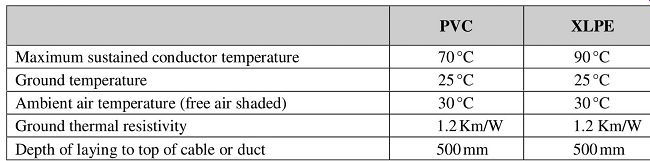
TABLE 17 Current rating parameters.
De-rating factors for non-standard conditions
___ show the de-rating factors to be used for calculating the current-carrying capacity when these cables are used under non-standard conditions. These de-rating factors are applicable for both XLPE and PVC-insulated LV cables.
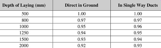
TABLE 18 De-rating factors for depth of laying - multicore cables (up to
300 mm^2)
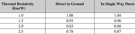
TABLE 19 De-rating factors for ground thermal resistivity (multicore cables)
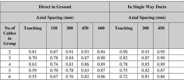
TABLE 20 De-rating factors for grouping of cables in horizontal formation,
at standard depths of laying and in standard soil conditions.
Multicore Cables (up to 300 mm^2 )
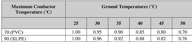
TABLE 21 Ground temperature de-rating factors.
Multicore Cables (up to 300 mm^2 )

TABLE 22 Air temperature de-rating factors.
D* is the overall diameter of one cable.
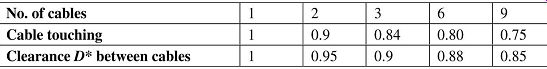
TABLE 23 De-rating factors for grouping of multicore cable installed horizontally
in air
Note: Cables may be grouped in air without derating, provided that the cables are installed on ladders, and that for:
• Horizontal formation: The clearance is greater than 6 × the cable overall diameter (or 150 mm^2, which- ever is the least).
• Vertical formation: The clearance from a vertical wall is greater than 20 mm, and the vertical clearance between cables is greater than 150 mm.
Note: If the number of cables > 4, they should be installed in the horizontal plane.
Short-circuit ratings for PVC and for XLPE-insulated 600/1000 V cables:
With PVC and with XLPE-insulated cables, care must be taken to limit the conductor temperatures for continuous operation and for short-circuit conditions as indicated.
Short-circuit ratings are regarded as internal ratings. Their calculation is based on an adiabatic equation and is not affected by external consideration. Due to unknown variables, short-circuit ratings don’t lend themselves readily to rigid treatment, so whenever possible conservative values should be applied.
Where SC = short-circuit rating in amps:
= a constant combining temperature limits and properties of conductor materials
= area of conductor
= duration of short circuit in seconds
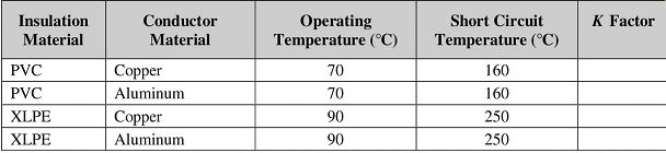
TABLE 24 Values of conductor/temperature constant K
Copper conductors:
=== the electrical and physical properties of different types of cables for use in cable-sizing calculations. Diameters D1, D2 and d referred in these tables are as per the legend, which shows the typical constructional details of a PVC insulated 3-core armored cable. The types of cables for which the physical and electrical properties are shown in these tables as follows.
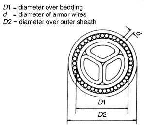
FIG. 6. Cross-sectional view of a PVC 3-core cable

TABLE 25 3- and 4-core PVC-insulated, 600/1000 V copper cable
TABLE 26 3- and 4-core XLPE-insulated 600/1000 V copper cable
TABLE 27 3-core 6.35/11 kV PILC-insulated copper and aluminum cables
TABLE 28 3-core XLPE-insulated 6.35/11 kV copper and aluminum cables -- Copper Conductors Stranded Aluminum Conductors
TABLE 29 Single-core PVC- insulated cables with stranded copper conductors -- Nominal Diameters; Current Ratings Phase Current Ratings -- Phase Trefoil Formation
| Top of Page | PREV: Paper-insulated and lead-covered (PILC) | NEXT: Electric Power Distribution and Compensation | Index |