
AMAZON multi-meters discounts AMAZON oscilloscope discounts
Paper-insulated and lead-covered (PILC)
The following section covers 6.35/11 kV PILC cables.
 Notes on impregnating compound Present day paper-insulated cables are mass
impregnated with non-draining compound (MIND). This poly isobutylene compound
remains in a solid state at normal operating temperatures and melts at
approximately 100 °C. Compound migration, as was experienced in earlier rosin
oil-impregnated cables installed vertically or on inclines, has thus been
eliminated by the use of this non-draining compound.
Notes on impregnating compound Present day paper-insulated cables are mass
impregnated with non-draining compound (MIND). This poly isobutylene compound
remains in a solid state at normal operating temperatures and melts at
approximately 100 °C. Compound migration, as was experienced in earlier rosin
oil-impregnated cables installed vertically or on inclines, has thus been
eliminated by the use of this non-draining compound.

Moisture in paper cables:
If a cable is damaged and the lead sheath or end cap is punctured, moisture almost invariably penetrates into the insulation and, if not detected immediately and removed, may cause trouble at a later date. In every such case, therefore, a moisture test should be carried out and the cable cut back until all traces of dampness are removed. The following simple, but reliable test is recommended:
Moisture test:
Heat about 1 liter of oil compound (or melted paraffin wax) in a saucepan to a temperature of 150 °C (check by thermometer). Remove individual paper tapes from the cable under test and immerse them in the hot compound. If any moisture is present, it will boil out of the paper and form bubbles or froth, which will rise to the surface of the liquid. If no moisture is present, the hot compound will be undisturbed.

When carrying out the above test don’t handle the portion of the paper tapes to be immersed in the compound with bare hands, as moisture from the hands may give rise to false conclusions. As moisture is most likely to travel along the cable under the lead sheath or along the conductors, the papers next to the sheath and conductors are those most likely to contain moisture.
To minimize the penetration of moisture into the cable from the atmosphere or other sources, the cores should be moisture-blocked at each end, by sweating them solid or using solid center ferrules. ====4 shows the design ambient/installation conditions applicable for PILC-insulated 6.35/11 kV grade cables.
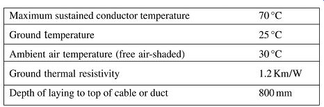
====4 Current rating parameters -- base values
Derating factors for non-standard conditions:
==== de-rating factors to be used for calculating the current-carrying capacity when the cables are used under non-standard conditions.
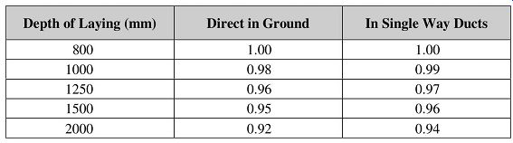
====5 Depth of laying - multicore PILC cables (up to 300 mm^2)
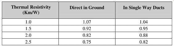
====6 Ground thermal resistivity (multicore PILC cables)
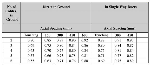
====7 Grouping of PILC cables in horizontal formation at standard soil
conditions (multicore cables).
Maximum conductor temperature: 70 °C

====8 Ground temperature de-rating factors Maximum conductor temperature:
70 °C
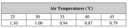
====9 Air temperature de-rating factors.
Note: PILC Cables may be grouped in air without derating provided that the cables are installed on cable ladders, and that for:
• Horizontal formation: The clearance between cables is not less than 6 × the overall diameter of the largest cable (or 150 mm) whichever is the least.
• Vertical formation: The clearance from a supporting wall is greater than 20 mm, and the vertical clearance between cables is greater than 150 mm.
Note: If the number of cables > 4, they are to be installed in a horizontal plane.
Why should more than four cables be installed in a horizontal plane, otherwise de-rating factors would apply?
Short-circuit ratings for PILC cables Short-circuit ratings don’t lend themselves to rigid treatment due to unknown variables, and wherever possible conservative values should be applied.
With the continued growth of power system fault capacity, attention must be given, when selecting a cable, to its short-circuit capacity as well as to the continuous current rating.
Other limiting effects in avoiding damage during subsequent short-circuit conditions are as follows:
• Weakening of joints due to softening of solder at conductor temperatures above 160 °C
• If crimped or welded ferrules and lugs are used, temperatures of 250 °C can be tolerated
• Bursting effects are only of concern with unarmored screened cables larger than 150 mm^2
. Multicore wire armored cables are only likely to burst at currents in excess of 33 kA for cable sizes below 70 mm^2 , in excess of 39 kA for cables below 150 mm^2 and in excess of 22 kA for cables below 300 mm^2. Cable short-circuit ratings are based on the adiabatic performance of the conductors and may thus be regarded as 'internal ratings' which are not affected by external factors as in the case of current ratings. Therefore, no derating factors are needed.
Formula for cable short-circuit current rating:
Where:
= short-circuit rating in amps
= constant combining temperature limits and conductor material properties
= area of conductor
= duration of short circuit in seconds
The values of K for copper and aluminum conductors of 6.35/11 kV PILC cables are 154 and 101A/ mm^2 respectively, for a conductor temperature rise from 70 to 250 °C. --- provides 1s short-circuit ratings. For other periods, apply the following formula.
Earth (ground) fault ratings Some systems make provision for reducing ground fault currents by the inclusion of a neutral electromagnetic coupler (NEC) at the star point of the distribution transformer.
Where this is not the case, the resultant high ground fault current under a fault condition will be carried by the lead sheath and by the galvanized steel wire armor. The bituminized steel tape armor is expected to rust in time and should not be included in any calculation to carry fault current.
The value of K for lead sheaths and galvanized steel wire armor is 24 and 44 A/ mm^2 respectively. The following formula must be applied:
The area of the lead sheath and the armor wires of the cable must be obtained.
| Top of Page | PREV: Transport, handling and installation of electric cables | NEXT: Power cables --part 5 | Index |