
AMAZON multi-meters discounts AMAZON oscilloscope discounts
Intro...

Transformer is an essential device in electrical AC power distribution system, which is used to transform AC voltage magnitudes of any value obtained from a source to any desired value for the purpose of distribution and/or consumption. The development of power transformer dates back to 19th century. The main feature of a transformer is its constant VA rating whether referred to its primary side or the secondary side. With VA being constant (V refers to the voltage magnitude and A refers to the current magnitude in a transformer winding), it’s possible to get a higher V with lower A or a lower V with a higher A, by choosing suitable ratio for the transformer. The major benefit of such a device is its ability to take in the high current produced at relatively low voltage from the electrical generators and transform this power at a higher voltage level with lower current. This ensures that the power generated in the order of several megavolt amperes (MVA) is being transmitted at low current magnitudes in a cable of practical dimensions over very long distances. Today's transmission and distribution systems are heavily dependent upon this technology and transformers are used extensively throughout the world.
AMAZON multi-meters discounts AMAZON oscilloscope discountsThe standard transformer:
A standard transformer typically consists of a pair of windings, primary and secondary linked together by a magnetic core. The windings can be connected in any of the following types, which in turn decides to which category a transformer belongs. There are two basic types of the transformer viz., (a) shell type and (b) core type.
... the windings are the concentric portions and the white solid portions refer to the metallic part of a transformer (laminations), which either surround the windings (shell type) or where the windings surround the core (core type). The windings are normally made of electrolytic grade copper and the metallic parts are made of steel (usually special steel called lamination steel). The metallic part linking the windings is referred to as the magnetic core of a transformer. In these transformers the source will be connected to just one winding only, which is termed as the primary winding. The voltage will be induced magnetically through the magnetic core linking the flux in the core with the other winding (called the secondary winding), since it derives its power from the primary winding.
AMAZON multi-meters discounts AMAZON oscilloscope discounts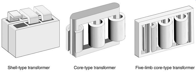
FIG. 1. Transformer types.
When an alternating current is applied to the primary winding, an alternating magneto motive force (mmf ) is induced into the magnetic core and subsequently sets up an alternating flux passing through its body. This alternating flux in the core that links both the primary and secondary windings induces an electro motive force (emf ) in both the windings. In the primary winding this emf is referred to as the back-emf and in an ideal situation, it would oppose the applied voltage to the primary windings such that there would be no flow of current (according to Lenz's law). However the impedance in the windings causes a low current to pass in the primary winding and the current that flows in the primary winding is termed as the transformer magnetizing current. In the open secondary winding, this induced emf is referred to as the secondary open-circuit voltage, which basically refers to the voltage measured between the two ends of the winding. FIG. is the vectorial representation of the voltages, flux and currents that flow in a simple single phase transformer neglecting its impedances. The descriptions of the parameters are identified on the left hand side, which will give a clear idea on the phase angle differences between the voltages, currents and flux in a typical single phase transformer windings and its core.
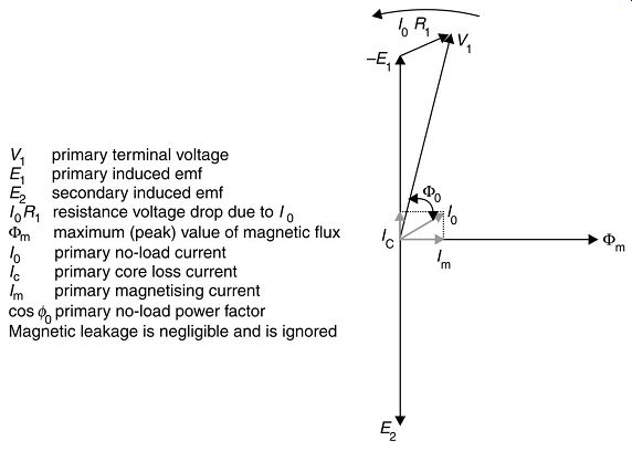
FIG. 2. Phasor diagram for a single-phase transformer on open circuit.
If a load is connected to the secondary winding across its two ends it will result in flow of current through the load, value of which depends upon the open circuit voltage across the secondary winding and the load impedance. This load current creates a demagnetizing mmf in the magnetic core upsetting the balance between the primary applied voltage and the already induced back-emf. To re-establish this equilibrium an additional current must be drawn from the primary supply source to provide an exactly equivalent mmf. FIG. the phasor diagram for a single-phase transformer supplying a pure resistive load, where the current I2 in the secondary winding is in phase with its induced emf E2 (unity power factor).
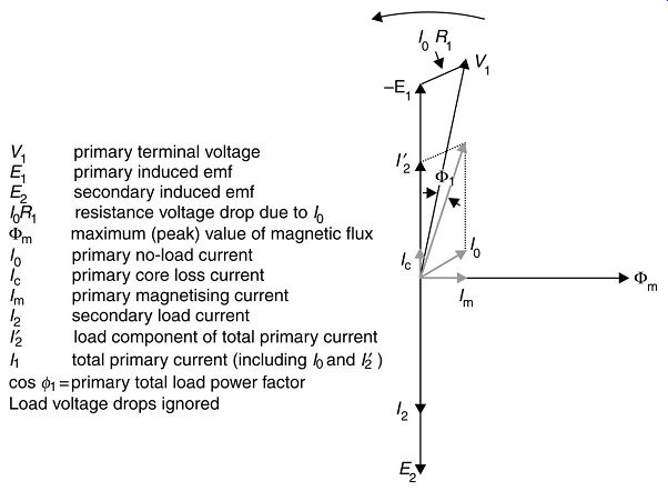
FIG. 3. Phasor diagram for a single-phase transformer supplying a unity
power factor load.
Losses in core and windings:
Energy is dissipated when the magnetizing current passes through the core in the form of alternating cycles of flux, the cycles being determined by the system frequency. The various losses dissipated in an open circuited transformer are core loss and no-load loss (also referred as iron loss). These losses are identified in above in terms of current. The iron loss is always constant since it’s dissipated whether a load is connected across the secondary winding or not. When a load is connected across the secondary, the flow of load current and the mmf. It produces in the secondary winding are balanced by an equivalent increase in the primary load current and the mmf it produces, thereby indicating that the iron loss is independent of the load.
As a fundamental phenomenon, transformer windings also dissipate losses when currents flow in the windings with secondary winding being connected to a load. The magnitude of these losses in the primary and secondary windings will depend upon the magnitude of the current and the resistance of the total system. This is termed as load loss or copper loss of a transformer (basically referring to the losses in copper windings, though modern day transformer windings adopt materials other than copper). As a fundamental electrical law, the losses in a conductor having resistance value R is I^2R where I is the current flowing through the conductor. In the same way, the total load loss in a transformer is found to be proportional to the square of the load current since the no-load current produces very negligible resistive loss in the windings.
Leakage reactance:
It’s not practically possible to ensure that all of the flux produced by the primary winding source is linked to the secondary winding. Due to limitations in the materials used and in the design of transformer cores some flux 'leaks' out of the core and flows through the air -- this is termed leakage flux. It’s convention to allocate half the leakage flux to both the windings, as it’s difficult to quantify exactly the leakage flux contribution to the primary and the secondary windings.
So the transformer can be said to possess leakage reactance due to imperfect trans formation between primary and secondary windings. Practically this is expressed as transformer impedance, since transformer windings also have resistance and this impedance is normally expressed as a percentage voltage drop in the transformer at full load current.
Expressed mathematically this is:
...
Typical impedance values for a medium-sized power transformer are about 9-10%. Occasionally transformers are deliberately designed to have impedances as high as 22.5%. ====1 lists typical impedance values for a range of standard transformer ratings, normally found in transmission and distribution systems.
Size MVA Voltage Rating kV
MVA 12 kV 33 kV 72.5 kV 145 kV 250 kV 300 kV 420 kV
0.5 4.75% 5.0% 5.5%
0.8 4.75% 5.0% 6.0%
5 4.75% 5.0% 6.0% 7.0%
10 9.0% 9.0% 10.0% 10.0%
20 10.0% 10.0% 15.0% 13.0%
30 15.0% 15.0% 12.0% 13.0%
60 12.0% 12.5% 12.5% 15.0% 15.0% 16.0%
100 16.0% 17.5% 18.0%
====Typical percentage impedance of 50 Hz three-phase transformers===
Basic transformer equations:
It’s observed that the magnetic flux in a transformer core induces voltage in both the primary and secondary windings. Assuming a case where both primary and secondary winding have just one turn each with identical material it’s simple logic that there can be no difference between the voltage induced in both of these turns, whether it belongs to the primary or secondary winding. Hence it follows simply that the total voltage induced in each of the windings by the common flux must be proportional to the number of turns used in the respective windings. Thus, this establishes the well-known following relationship in a transformer: 12 1 2 / / EE NN = and expressed in terms of power balance: 11 2 2 EI EI = In terms of current balance, 11 2 2 IN IN =
Where E, I and N are the induced voltages, the currents and number of turns, respectively in the two windings, with suffix 1 denoting the primary winding parameters and suffix 2 denoting the secondary winding parameters. The other known term for IN is ampere turns of a transformer which is a constant factor for a transformer of a particular capacity. Thus the voltage is transformed in proportion to the number of turns in the respective windings and the currents are in inverse proportion.
Faraday's law establishes that the magnitude of the induced voltage in a winding is proportional to the rate of change of flux linkage associated to the winding. Further Lenz's law proves that the polarity of the induced voltage is such as to oppose that flux linkage change if current were allowed to flow, and this is expressed as:
In practical terms it can be shown that the voltage induced per turn of a winding is:
Where, K is a constant, Fm is the maximum value of total flux in Webers linking that turn and f is the supply frequency in hertz. If the voltage is sinusoidal, K is 4.44 and equation becomes:
For design calculations, the same can be expressed in terms of volts per turn and flux density in the core:
Where…
E/N = volts per turn, which is the same in both the windings
Bm = maximum value of flux density in the core, tesla
A = net cross-sectional area of the core, mm^2
f = frequency of supply, Hz
The above equation is basically used to decide the transformer construction parameters, voltages, number of turns, core area, etc.
Equivalent circuit:
The above equations prove that there is a simple relationship between the primary and secondary windings in terms of voltage, current, etc. The above equations can be used to relate the impedance parameters to a common side, so that the whole transformer can be converted to a simple inductive circuit with an applied voltage, internal impedance and the current flow being determined by the load connected to the secondary side. In simple terms the circuit will look as shown.
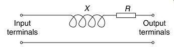
FIG. 4. Simplified equivalent circuit of leakage impedance of two winding
transformer.
The transfer of primary impedance on to the secondary is done as follows:
Let total impedance of the secondary circuit including leakage and load characteristics equivalent value of when referred to the primary winding
Comparing equations it will be seen that = ( 1/ 2) .
Transformers connected to load:
The earlier clauses referred to characteristics of a transformer with a simple resistive load connected to the secondary resulting in secondary current to be in phase with its voltage.
However in practical terms, the loads connected to a transformer are inductive in nature.
Assume a transformer connected to a load of Z2 across its secondary. In vectorial representation, FIG. the various parameters of a transformer, which is connected with an inductive load consisting both resistive and reactive components (R and X ) . The primary parameters are identified with suffix 1 while the secondary winding parameters are suffixed with 2.
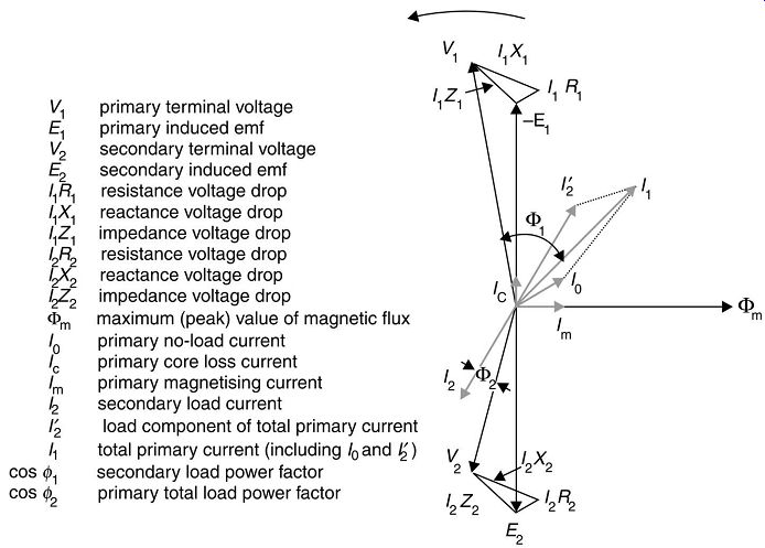
FIG. 5. Phasor diagram for a single-phase transformer supplying an inductive
load of lagging power factor cos F2. Voltage drops divided between primary
and secondary sides.
It’s to be noted that the basic phasor diagram still looks the same except for the lagging power factor introduced in the currents of both primary and secondary windings. In fact, the sum total effect is a reduction in the secondary terminal voltage.
The drops due to primary resistance and leakage reactance can be converted in terms of the secondary voltage using the transformer equations. FIG. the phasor conditions where the resistance and leakage reactance drops are shown as occurring on the secondary side with all parameters transferred to secondary side adopting the transformer equations.
What happens when the load on the secondary is capacitive in nature? In fact, there will be a rise in the voltage. This happens when a leading current passes through an inductive reactance (which is the transformer itself). Preceding phasor diagrams have illustrated the relationship between the various voltages and currents and the phase angles between them for a single-phase transformer. These phasor diagrams are applicable for polyphase transformers too, except that there will be an angular difference between the parameters (phase difference of 120° between the phasewise parameters in a three-phase transformer). In all other respects, the individual phases emulate almost same type of characteristics as single phase ones.
Rated quantities:
As described in the initial paragraph, the transformer rating is specified in voltamperes indicating the amperes A can handle at a rated voltage V. Depending on the magnitude of power being transferred or handled, the transformer rating or output can be expressed in MVA or in kilovoltamperes (kVA), and are determined by the following equations:
Single-phase transformers:
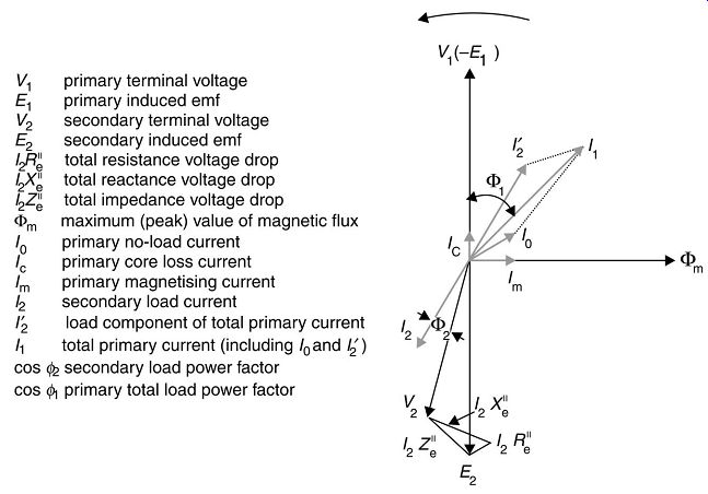
FIG. 6. Phasor diagram for a single-phase transformer supplying an inductive
load of lagging power factor cos F2.
Voltage drops transferred to secondary side
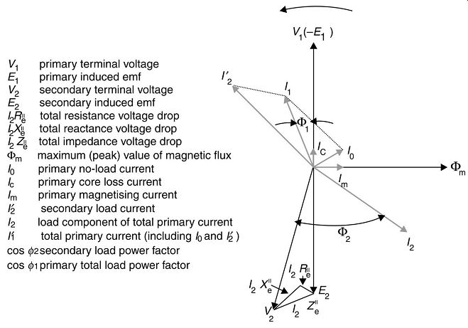
FIG. 7. Phasor diagram for a single-phase transformer supplying a capacitive
load of leading power factor cos F2.
Voltage drops on primary are transferred to secondary side
Three-phase transformers:
A three phase transformer basically consists of three windings and is used to transmit the three-phase power produced by a generator. The three-phase transformer also has primary and secondary windings, same as a single-phase transformer, but the windings of each phase are separately wound and brought out for both primary and secondary with the primary terminals connected to the three-phase source. The three windings of the primary and secondary can be connected in the form of either star or delta. However in a three phase transformer whether connected in star or delta form,
Output = with the multiplier 10^-3
for kVA and 10^-6
for MVA. Where I2 is the full-load current in the transformer secondary winding. The constant v3 is a multiplier for the conversion of phase voltage to line voltage in case of star-connected windings and is a multiplier for the conversion of phase currents to line currents in case of delta-connected windings. E2 and I2 are the rated secondary (no-load) voltage and the rated full-load secondary current.
Regulation It has been noted that due to the load impedance, there is a drop in the secondary terminal voltage as the load current increases (V2 = E2 - I2Z). This voltage drop varies with the load current and is called the regulation of a transformer. The voltage drop in a transformer is effected by the resistive (R) and reactive (X ) components which together are called the impedance (Z ) of the transformer.
The copper loss in a transformer is due to the resistive component when a load current passes through the windings. Hence, R percentage resistance voltage at full load (voltage drop due to resistive component) copper loss 100 percentage reactance voltage (voltage drop due to reactive component) ...
Based on the above equations and referring to the phasor diagrams, it can be mathematically proven that the approximate percentage regulation at a particular load current equaling 'a' times full load current of the transformer with a power factor of cos F2 is given by:
The percentage regulation that occurs at the secondary terminals, at unity power factor load (cos F2 = 1 and sin F2 = 0 may be calculated by simplifying the above equations as below:
Copper loss 100 (percentage reactance) -- output 200
This value is always positive and indicates a voltage drop with load.
For transformers having low reactance values up to about 4%, this can simplify to: R2X2 Percentage regulation ( cos F sin F )
aV V =+
For transformers with high reactance values about 20% and above:
Percentage regulation cos F, sin F
It had been noted that the secondary voltage will get increased by increasing its number of turns ratio with respect to the primary. This characteristic is used to offset the regulation in a loaded transformer. The transformer is provided with additional winding with suitable taps for external connection. Normally this provision is made on the high-voltage side to keep the current to be controlled at a lower value. Whenever there is a voltage drop, the taps are changed to a lower position to get a proportional increase in the turns ratio between primary and secondary so that a higher voltage can be obtained on the secondary side.
On-load tap changers:
On-load tap changers are very necessary to maintain a constant voltage on the LV terminals of the transformer for varying load conditions where the voltage had to be maintained constant without interrupting the power supply.
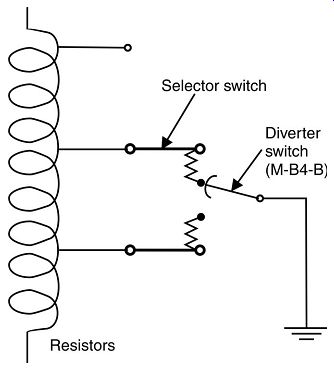
FIG. 8. On-load tap changer.
This is achieved by providing taps as shown below on the HV winding. The diverter switch is controlled by a motor which ensures that the switch is stepped up or down from one tap to the next taps until the desired secondary voltage is obtained.
The ranges are normally chosen depending upon the input supply conditions also. A typical range of taps could be +15% to -5% giving an overall range of 20%.
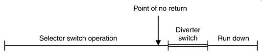
FIG. 9. Tap changer range of operations.
The tap changer is usually mounted on a separate tank to the main tank.
The tap changing can also be done by disconnecting the source (or load) by using off circuit tap switch, which necessarily requires an interruption in power supply to the load.
The off-circuit tap switch is manually changed from one step to another depending on the input conditions. It’s a well-accepted practice to provide off-circuit taps from -5% to +5% in steps of 2.5% (total five steps).
The on-load changer which is comparatively costlier is adopted in case of larger and important transformers mostly in continuous process industries, whereas off-circuit change is adopted in the case of almost all smaller distribution or auxiliary transformers.
| Top of Page | PREV: Caution: effect of shunt capacitors on induction motors | NEXT: Transformer design applications | Index |