AMAZON multi-meters discounts AMAZON oscilloscope discounts
In shell-type transformers, the flux-return paths of the core are external to, and enclose the windings (three-phase shell-type transformer). The shell-type arrangement provides intrinsically better magnetic shielding that is well suited for supplying power at low voltages and heavy currents. This design is widely used in arc furnace transformers.
AMAZON multi-meters discounts AMAZON oscilloscope discountsThe core-type designs are extensively used throughout the world for other types of transformers. These have concentric windings around the various limbs. This design possesses top and bottom yokes of cross-section equal to the wound limbs, thereby not requiring separate flux-return paths. In the event of very large transformers, where transportation becomes a problem, the cross-section of the top and bottom yokes are reduced to almost 50% of that of the wound limbs. This necessitates additional flux-return paths which are achieved by adopting five-limb transformer design.
AMAZON multi-meters discounts AMAZON oscilloscope discountsTransformer winding connections and phasor relationships:
The most common arrangement for any transformer is to have only two windings per phase, a high-voltage winding and a low-voltage winding (primary and secondary). As already noticed, a three-phase transformer can have its windings connected either in star or in delta with 120° displacement between each phase supply. The following paragraphs explain the different characteristics of transformers depending upon the connection method adopted.
Depending on the method chosen for the primary and the secondary connections, a phase-shift can take place through the transformer from primary to secondary.
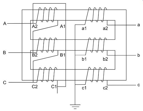
FIG. 10.Physical connection of delta (D) or star (Y) configuration
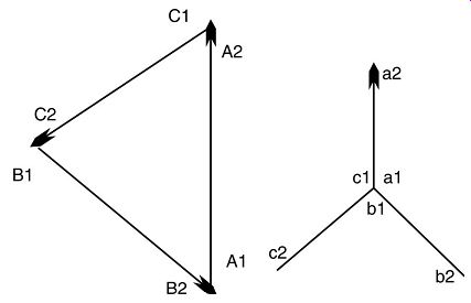
FIG. 11. Vectorial representation of delta and star configuration
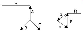
FIG. 12. 30° phase shift of transformer
FIG. consolidated phase shift phenomenon of a two-winding three phase transformer, when one winding is delta connected and the other is star connected (A-B-C refer to primary terminals and a-b-c refer to secondary terminals). In the example shown, the phase shift of secondary winding is 30º with respect to the corresponding primary winding. i.e. the a-n voltage lags A-N by 30º, b-n voltage lags B-N by 30º and so on. The vector diagram is considered analogous to a clock whose hour hands also rotates 360º same as the full cycle of a vector. Considering a clock with 12-h positions, each hour position corresponds to 30º shift when you start looking after the 12 o'clock position. Hence the above connections achieve an equivalent of 1 o'clock position with respect to its corresponding primary voltage. This connection is referred to as the 1 o'clock position. In simple terms this is referred to as Dyn1 (small n represents a connection where secondary neutral is brought out for external connection).
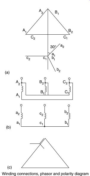
FIG. 13. Winding connections, phasor and polarity diagram.
Considering the same example, if the primary delta connection had been made by connecting A1B2, B1C2 and C1A2 this would have resulted in a phase displacement of 30º anticlockwise on the secondary side, i.e. the 11 o'clock position. This type of connection is termed as Dy11 (or Dyn11). In a similar way the transformer winding connections can be expressed in different ways.
For example:
YNd1 = HV winding connected in star with primary neutral (capital N) brought out.
LV winding connected in delta.
Phase shift 30º from 12 to 1o'clock.
==== Various group numbers that transformer phasors can be categorized, representing the induced emfs and the counter clockwise direction of rotations.
====Group numbers.
Inter-phase connections of the HV and LV windings are indicated.
====Winding connection destinations
Winding polarity:
International standards define the polarity of the HV and LV windings sharing the same magnetic circuit as follows.
If the core flux induces an instantaneous emf from a low-number terminal to a high number terminal in one winding, then the direction of induced emf in all other windings linked by that flux will also be from a low-number terminal to a high-number terminal (A1 to A2 and a1 to a2).
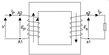
FIG. 14. Principle of operation of a transformer.
From the laws of induction, it will be seen that the current flow in the windings is in the opposite direction.
FIG. testing connections and method to determine the polarity of a transformer.
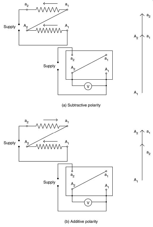
FIG. 15. Test connections for determining single-phase transformer winding
polarity The connections basically require interconnecting the phase terminals
of primary and secondary windings, applying voltage to one set of winding
and measuring the voltage across the various terminals caused by the induction
phenomenon. As is evident from the diagrams, if the voltage measured across
A1-A2 is less than the voltage measures across A1-a2 then the polarity is
said to be subtractive, and if it’s greater than, then the polarity is additive.
FIG. test connections for a three-phase star/star-connected transformer with subtractive polarity.
Polarity forms an important requirement for connecting the current transformers in the transformer windings to ensure that the current is sensed in the correct direction of flow before deciding the fault conditions for tripping purposes. FIG. shows how the phase relationships and the polarities can undergo changes depending upon the phase sequence followed in the primary connections and changing the star point on the secondary side. These changes can have different effects on the relays being connected and their operation.

FIG. 16. Test connections for determining three-phase transformer winding
polarity
Transformer grounding:
Earthing/grounding is a major requirement in most electrical systems to limit the fault currents, and transformers being the prime source of power distribution, the grounding of transformers takes utmost priority in a system. It’s obvious that the transformers shall have a neutral reference point for the three phases so that this point can be connected to ground. As a consequence, it’s convenient to have most three-phase transformer windings in a star connection that provides a neutral that could be connected to ground. This connection to ground could be direct or through a current limiting resistor, or other similar devices.
Earthing/grounding of system neutrals primarily falls in to three categories:
1. Solidly grounded neutral
2. grounding via an impedance
3. Isolated neutral (unearthed).
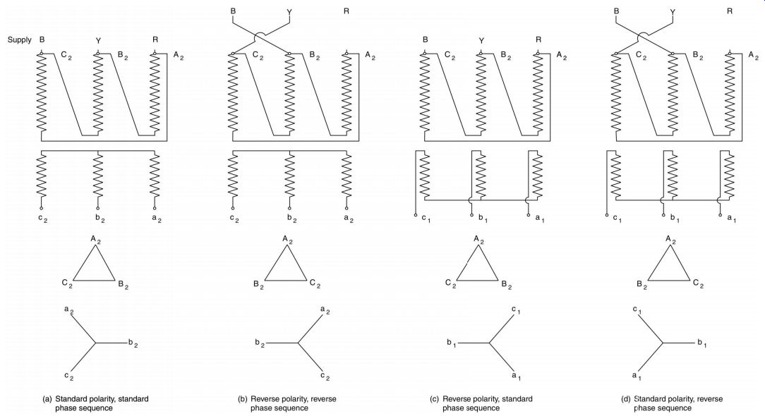
FIG. 17. Diagrams showing four examples of a three-phase delta/star-connected
transformer having different polarity and phase sequence.
The third alternative is rarely seen due to the problems and disadvantages associated with an isolated ground. The method of grounding low-voltage and high-voltage electrical systems differ. The definitions of high voltage and low voltages would differ from country to country and even region to region, but in practice, usually any system over 50 V but not exceeding 1000 V is considered a low-voltage system. The low-voltage systems' neutrals are required to be solidly connected to ground and no impedance shall be inserted in any connection with ground, except in cases where they are required for operation of switchgear, etc.
Some of the advantages of connecting high-voltage systems to ground are:
• ground faults effectively become short circuits from line to neutral thereby protecting equipment from serious damage occurring from high-voltage oscillations.
• An grounded neutral allows rapid operation of protection the instant ground faults occur, working in conjunction with sensitive fault protection devices, to isolate the faulty sections quickly.
• Solid grounding of neutrals ensures that the voltage of any live conductor never exceeds the voltage between the line and neutral, effectively maintaining the neutral at zero volt potential.
• grounded neutrals provide added protection against capacitance effects on overhead lines that are subject to induced static charge from adjacent charged clouds, dust, sleet, fog, rain and changes in altitude of the lines.
• The HV winding can have graded installation; thus making the transformer smaller and cheaper.
The only disadvantage of connecting a high-voltage system to ground is that it introduces susceptibility to ground faults. This is particularly inconvenient for long overhead transmission lines in lightning prone areas, but as this phenomenon is only transient in nature, and is cleared immediately following a trip, this disadvantage is far outweighed by the advantages listed above.
An ground fault condition is also a reason for flow of third harmonic currents in an electrical system and higher magnitude third harmonics are undesirable. However the third harmonics can be eliminated if a separate path could be created for the flow of third harmonic currents. Hence to provide a path for the third harmonic currents in order to eliminate or attenuate the third harmonic voltages, it’s also desirable to have a delta connected three-phase system. Considering the need for grounding and the need to eliminate third harmonics, in most three-phase step down transformers it’s convenient to have the high-voltage (HV) winding delta-connected and the low-voltage ( LV) winding star-connected, with the neutral grounded.
Different methods of grounding neutrals:
It’s important that the neutral of a power system be grounded; otherwise, this could 'float' all over with respect to true ground, thereby stressing the insulation above its design capability.
On HV systems (i.e. 6 kV and above) it’s common practice to effectively ground the neutral by means of a solid bar of copper. This has the advantage that when a ground fault occurs on one phase, the two healthy phases remain at phase-to-neutral voltage above ground. This allows insulation of the transformer windings to be graded toward the neutral point, resulting in a significant saving in cost. In addition, all other primary plant need only have phase-to-neutral insulation and surge arrestors in particular need only be rated for 80% line-to-line voltage. This provides an enormous saving in capital expenditure and explains why utilities HV system is invariably solidly grounded.
FIG. 18. grounding of the neutral
The disadvantage is that when an ground fault occurs, an extremely high current flows (approximately equal to three-phase fault current), stressing the HV windings both electromagnetically and thermally, the forces and heat being proportional to the current squared.
Earthing of the LV system can be achieved.
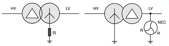
FIG. 19. grounding of the LV system.
It will be noted that the LV system is impedance and/or resistance grounded. This allows the ground fault current to be controlled to manageable levels, normally of the order of the transformer full load current, typically 300 A. Here, the transformer does not get a shock on the occurrence of each ground fault, however, the phase conductors now rise to line potential above ground during the period of the ground fault. It’s recommended to use neutral grounding resistor (NEC/R) to limit severe overvoltages in the healthy phases of a single phase faulted system by damping the oscillations. The idea is supported and encouraged by IEEE standard 142.
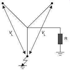
FIG. 20. Phasor diagram illustrating phase conductors rising to phase voltage
on fault.
Phase-to-earth insulation of all items of primary plant must therefore withstand line-to line voltage.
There is a case where the secondary of a transformer is delta connected without neutral.
These types of transformers can be connected in the following way for grounding purposes.
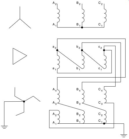
FIG. 21. Transformer with delta secondary and interconnected star grounding
transformer with a neutral connected to ground.
The criterion that is to be considered is to decide whether to have a solid connection of the system neutral to ground or to introduce impedance in the circuit to ground. The value of the impedance must be such that the total current flow to ground is limited thereby limiting the amount of damage caused at the point of the ground fault. In keeping with this, FIG. two different methods of providing an grounded neutral to a star/delta transformer. Each offers two possibilities of providing grounding resistors and an artificial neutral for the delta windings that normally don’t possess one.
In one case only one resistor is required that is designed to carry the total fault current to ground, while being insulated for the total phase voltage of the system. On the other hand, in the event of a fault, the neutral of the transformer will rise above the ground potential, equal to the potential drop across the grounding resistor, and the transformer windings will have to be insulated for the full line voltage above ground.
Alternatively in order to avoid sudden high-voltage changes in the insulated windings which is the most vulnerable component of the equipment, the second option should be chosen of installing suitably sized resistors between the lines and the grounding transformer rather than between the neutral and ground. In doing so the purpose of current limiting is achieved and in addition the neutral of the grounding transformer remains at ground potential and the windings are not subjected to any high voltages.
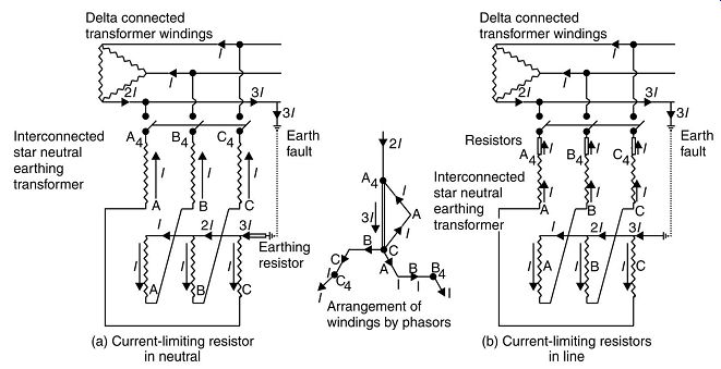
FIG. 22. Interconnected star neutral grounding transformer
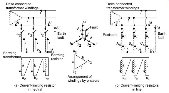
FIG. 23. Three-phase, star/delta neutral grounding transformer
The value of these grounding resistors may be calculated simply by applying Ohm's law:
Frequently used devices for grounding high-voltage neutrals are the liquid neutral grounding resistor (LNER), and are capable of withstanding currents up to 1500A for about 30s. This type of resistor required regular maintenance like topping up of the electrolyte and maintaining its strength and fluidity in extreme winters by employing heaters, etc. To overcome this shortcoming, solid metal resistors may be used; of course this flexibility does come with additional costs.
As an alternative to grounding resistors and the associated problems, many substations use an arc suppressor. This device called a Petersen coil is a reactor connected between the neutral of the supply transformer and ground, and its reactance is tuned to match the capacitance of the power system it’s protecting. FIG. a typical oscillogram of voltage recovery after arc suppression.
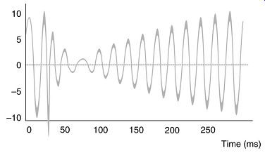
FIG. 24. Recovery voltage after initial arc extinction.
In the event of a sustained fault condition, the arc suppression coil allows the power system to be operated in a faulted condition until the fault can be located and removed.
Nowadays solid-state tap switching control devices are employed in conjunction with arc suppression coils to achieve more efficient compensation.
In some instances when the high-voltage winding is common with the low-voltage winding for economic advantages, such a type of transformer is known as an autotransformer. These are most exclusively used to interconnect very high-voltage systems. Three-phase autotransformers are invariably star/star-connected and their use requires that the systems that they interconnect are able to share a common grounding arrangement.
Transformers with tertiary windings
It’s most common to come across transformers with a third winding called tertiary winding in addition to primary and secondary windings. This is adopted in large size transformers in power stations and large switching substations. The most common reason for the additional third set of windings to a three-phase transformer is for the provision of a delta-connected tertiary winding to provide path for the third harmonics. Other reasons are:
• To limit the fault level on the LV system by subdividing the infeed -- i.e. double secondary transformers
• The interconnection of several power systems operating at different supply voltages
• The regulation of system voltage and of reactive power by means of a synchronous capacitor connected to the terminals of one winding.
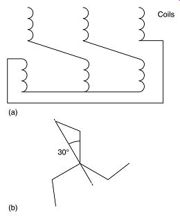
FIG. 25. Interconnected star winding arrangement.
As has been mentioned earlier in this section, it’s desirable that a three-phase transformer has one set of three-phase windings delta-connected, thus providing a path for third harmonic currents. The presence of delta-connected windings also allows current to circulate around the delta in the event of an unbalance in the loading between the phases, so that this unbalance is reduced.
If the neutral of the supply and the star-connected winding are both grounded, then although the transformer output wave form will be undistorted, the circulating third-order harmonic currents flowing in the neutral can cause interference with telecommunications circuits and other electronic equipment. Further it can cause unacceptable heating in any neutral grounding resistors, so this provides an added reason for the use of a delta connected tertiary winding.
If the neutral of the star-connected winding is unearthed then, without the use of a delta tertiary, this neutral point can oscillate above and below ground at a voltage equal in magnitude to the third-order harmonic component. Because the use of a delta tertiary prevents this, it’s sometimes referred to as a stabilization winding.
The load currents in the primary phases corresponding to a single-phase load on the secondary of a star/star transformer with a delta tertiary are typical, assuming a one-to-one turns ratio for all windings.
This leads to an ampere-turns rating of the tertiary approximately equal to one-third that of the primary and secondary windings and provides a rule-of-thumb method for rating the tertiary in the absence of any more specific rating basis.
Double secondary transformers
This is another type of multi-winding transformers where it’s required to split the number of supplies from a HV feeder to economize on the quantity of HV switchgear and at the same time limit the fault level of the feeds to the LV switchgear.
In designing the double secondary transformer, it’s necessary that both LV windings are disposed symmetrically with respect to the HV winding so that both have identical impedances to the HV. The two possible arrangements to achieve this (both instances there is a crossover between the two LV windings half way up the limb).
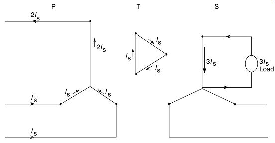
FIG. 26. Single-phase load to neutral.
The leakage reactance LV1 to LV2 in the first case would be high as the LV windings are loosely coupled due to the fact the inner LV upper half crosses to the outer upper half and the inner lower half crosses to the outer lower half. The leakage reactance LV1 to LV2 in the second case would be low as the LV windings are closely coupled due to the fact the upper inner crosses to lower outer and upper outer crosses to lower inner. Thus, the equivalent circuits for these two arrangements wherein the transformer is represented by a three terminal network and typical values of impedance (leakage reactance) are marked.
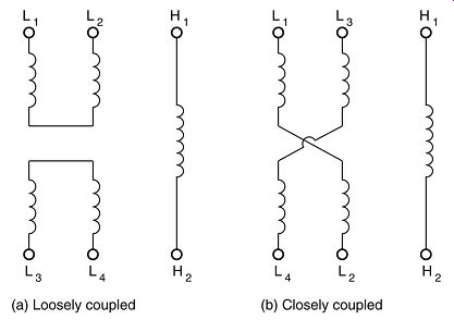
FIG. 27. Transformers with two secondary windings.
General case of three-winding transformer The basic voltage for each winding and any combination of loading is the no-load voltage obtained from its turns ratio. In considering the case of two output windings W2 and W3, and one input winding W1, there are three possibilities of loading conditions: W2 only loaded W3 only loaded W2 and W3 both loaded
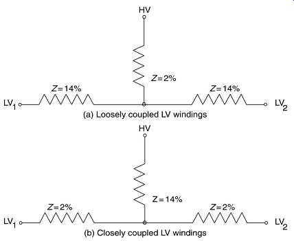
FIG. 28. Equivalent circuits for loosely coupled and closely coupled double
secondary transformers
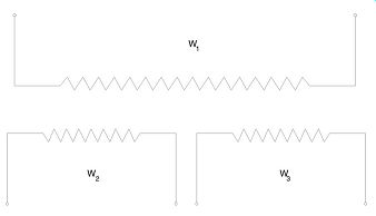
FIG. 29. Diagram of a three-winding transformer
Now based on each of these three loading conditions two separate values are calculated viz. the regulation of each output winding W2 and W3 for a constant voltage applied to winding W1, and the voltage regulation between W2 and W3 relative to each other. From this data an equivalent circuit is derived as follows:
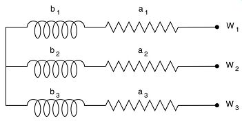
FIG. 30. Equivalent circuit of a three-winding transformer
Let a12 and b12 be the percentage of resistance and reactance voltage referred to the basic kVA respectively and obtained from test, short circuiting either winding W1 or W2 and supplying the other with winding W3 on open circuit, Similarly, a23 and b23 by test to windings W2 and W3 with W1 on open circuit, similarly, a31 and b31 by test to windings W3 and W1 with W2 on open circuit, …
Then calculating for a1, a2, a3, b1, b2 and b3 we get: Arm W1: a1 = d/2 - a23 and b1 = g/2 - b23 Arm W2: a2 = d/2 - a31 and b2 = g/2 - b31 Arm W3: a3 = d/2 - a12 and b3 = g/2 - b12 The regulation with respect to the terminals of any pair of windings is the algebraic sum of the regulations of the corresponding two arms of the equivalent circuit.
Following is an example calculation of voltage regulation of a three-winding transformer given: W1 is a 66 000 V primary winding W2 is a 33 000 V output winding loaded at 2000 kVA and having a power factor cos F 2 = 0.8 lagging.
W3 is an 11000 V output winding loaded at 1000 kVA and having a power factor cos F 3 = 0.6 lagging.
In addition, the following test data is also available, related to a basic loading of 1000 kVA. a12 = 0.26 and b12 = 3.12 a23 = 0.33 and b23 = 5.59 a31 = 0.32 and b31 = 5.08 Hence d = 0.91 and g = 9.79 Then for W1: a1 = 0.125 and b1 = + 3.305 W2: a2 = 0.135 and b2 = - 0.185 W3: a3 = 0.195 and b3 = + 5.775 The effective full-load kVA input to winding W1 is:
1. With only the output winding W2 loaded, 2000 kVA at a power factor of 0.8 lagging
2. With only the output winding W3 loaded, 1000 kVA at a power factor of 0.6 lagging
3. With both the output windings W2 and W3 loaded, 2980 kVA at a power factor of 0.74 lagging.
Applying expressions (5.9) or (5.10) separately to each arm of the equivalent circuit, the individual regulations have, in W1 under condition (i) where n1 = 2.0, the value of 4.23% W1 under condition (ii) where n1 = 5.0, the value of 2.72% W1 under condition (iii) where n1 = 2.98, the value of 7.15% W2 where n2 = 2.0, the value of -0.02% W3 where n3 = 5.0, the value of 5.53%
Summarizing these calculations, therefore the total transformer voltage regulation has:
1. With output winding W2 fully loaded and W3 unloaded At the terminals of winding W2, the value of 4.23 - 0.02 = 4.21% At the terminals of winding W3, the value of 4.23 + 0 = 4.23%
2. With output winding W2 unloaded and W3 fully loaded At the terminals of winding W2, the value of 2.72 + 0 = 2.72% At the terminals of winding W3, the value of 2.72 + 5.53 = 4.25%
3. With both output windings W2 and W3 fully loaded At the terminals of winding W2, the value of 7.15 - 0.02 = 7.13% At the terminals of winding W3, the value of 7.15 + 5.53 = 8.68%.
Terminal markings of transformers
To ensure proper design and installation, individual phase windings are given descriptive letters and the same letter in combination with suffix numbers is then used for all windings of one phase. The HV windings are given upper case letters and the LV windings are given lower case letters for corresponding phases.
Thus for single-phase transformers: A : for the HV winding 3A : for the third winding (if any) a : for the LV winding For two-phase windings on a common core or separate cores in a common tank: AB : for the HV windings ab : for the LV winding For three-phase transformers: ABC: for the HV winding abc : for the LV winding FIG. the standard markings of a single-phase transformer.
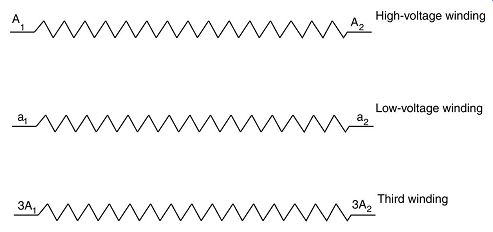
FIG. 31. Terminal marking of a single-phase transformer having a third
winding
FIG. shows the relative markings of a two winding transformers.
In addition to the letters marking the terminals, suffix numbers are given in sequence, relative to the direction of the induced emf, on all the tapping points and the ends of the winding. In the case of three-phase star-connected transformers, A1 would be connected to the star's neutral point and the A2 would be the line terminal. FIG. typical terminal markings of tappings.
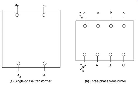
FIG. 32. Relative position of terminals of two-winding transformers
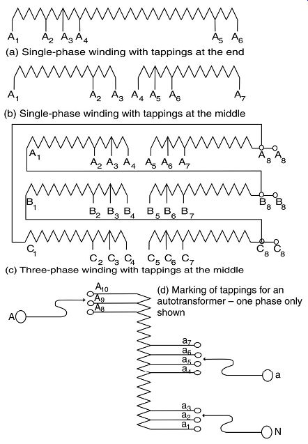
FIG. 33. Marking of tappings on phase windings
Parallel operation of transformers
Parallel operation of transformers occurs when two or more transformers are connected to the same HV and LV busbars, especially on the load side. This is a most common practice in generating stations and grid substations to operate transformers in parallel to ensure that in the event of transformer or generator failures, redundancy is built in the distribution to maintain power supply through healthy transformers. Five principal characteristics shall be met by each of the transformers to be operated in parallel:
1. Same inherent phase angle difference between primary and secondary terminals
2. Same voltage ratio
3. Same percentage impedance
4. Same polarity
5. Same phase sequence
For two transformers to operate in parallel it’s imperative that in addition to all of the above conditions, the phase sequence must also be the same. FIG. four instances of delta/star-connected transformer under different conditions of polarity and phase sequence. There could be cases where the phase sequence required in secondary side of one transformer could be different with respect to the other transformer.
In such a case, reversing the internal connections on one side of the transformer can change polarities but interchanging two of the primary supply leads can reverse the phase sequence. Referring to the transformers can be paralleled so long as the secondary leads from a1 and c1 to the busbars are interchanged.
Referring to below that typically represents a power station auxiliary system, we have a 660 MW generator generating at 23.5 kV that is stepped up to 400 kV via a generator transformer and with a unit transformer providing a supply to the 11 kV unit switchboard. While the unit is being started up, the 11 kV switchboard will normally be supplied via the station transformer that takes its supply directly from the 400 kV system. At some stage during the loading of the generator, supplies will be changed from the station transformer to the unit transformer, which will briefly involve paralleling these sources so it’s imperative that the supplies must be in phase.
The generator transformer will probably be connected star/delta with the 23.5 kV phasor at 1 o'clock, i.e. YNd1. The 23.5/11 kV unit transformer will be connected delta/star with its 11 kV phasor at the 11 o'clock position, i.e. Dyn11. This means that the 11 kV system now has a zero-phase shift compared to the 400 kV system. Thus, the station transformer must now connect the 400 kV system to the 11 kV system without any phase shift, and therefore this is achieved by utilizing a star/star-connected transformer.
Paralleling of two identical transformers reduces the combined impedances to half that of the individual transformers, resulting in the increase of the fault level of the LV busbar.
This is to be taken into consideration while designing distribution equipment and protective relaying for transformers operated in parallel.
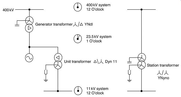
FIG. 34. Power station auxiliary system.
| Top of Page | PREV: Intro to Transformer theory | NEXT: Transformer construction / installation | Index |