AMAZON multi-meters discounts AMAZON oscilloscope discounts
High-Voltage (HV) overcurrent:


The most common protection employed in a transformer is protection against withdrawal of currents from the source in excess of rated/design values. Also it’s quite common that a ground fault or inter-phase faults in a transformer winding could be the cause for flow of fault currents many times the rated design current. The most common protection against such drawing of excess currents is by using an IDMTL (inverse definite minimum time) overcurrent and ground fault relay on the HV side of a transformer. The operating time varies inversely with respect to the current values and the operating time can be set to the desired values in these relays. The inherent time delay of the IDMTL element provides back-up for the LV side.
AMAZON multi-meters discounts AMAZON oscilloscope discountsHigh-set instantaneous overcurrent is also recommended on the primary side mainly to give high-speed clearance to HV bushing flashovers. Care must be taken, however, to ensure that these elements don’t pick-up and trip for faults on the LV side as discrimination is important.
AMAZON multi-meters discounts AMAZON oscilloscope discountsFor this reason, it’s essential that the high-set overcurrent element should be of the low transient over-reach type, set approximately to 125% of the maximum through-fault current of the transformer to prevent operation for asymmetrical faults on the secondary side.
This relay therefore looks into, but not through the transformer, protecting part of the winding, so behaving like unit protection by virtue of its setting.
When grading IDMTL overcurrent relays across a delta-star transformer it’s necessary to establish the grading margin between the operating time of the star side relay at the phase-to-phase fault level and the operating time of the delta side relay at the three-phase fault level.
This is due to the fact that, under a star side phase-to-phase fault condition, which represents a fault level of 86% of the three-phase fault level, one phase of the delta side transformer will carry a current equivalent to the three-phase fault level.
Differential protection:
Differential protection, as its name implies -- compares currents entering and leaving the protected zone and operates when the differential current between these currents exceed a predetermined level.
The type of differential scheme normally applied to a transformer is called the current balance or circulating current scheme.
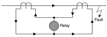
FIG. 44. Differential protection using current balance scheme (external
fault conditions)
The CTs are connected in series and the secondary current circulates between them.
The relay is connected across the mid-point where the voltage is theoretically nil, therefore no current passes through the relay, hence no operation for faults outside the protected zone.
Under internal fault conditions (i.e. faults in area within the two sets of CTs) the relay operates because there is an unbalance detected by the relay within its protective zone. (The CT currents tend to flow in the same direction through the relay making it to operate.)
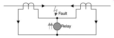
FIG. 45. Differential protection and internal fault conditions
This protection is called UNIT protection, as it only operates for faults on the unit it’s protecting, which is situated between the CTs. The relay therefore can be instantaneous in operation, as it does not have to coordinate with any other relay on the network.
This type of protection system can be readily applied to autotransformers as follows.
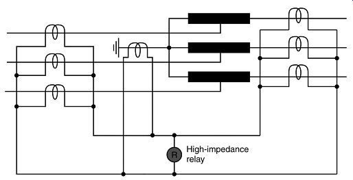
FIG. 46. Restricted ground protection applied to autotransformers
All current transformer ratios remain the same and the relays are of the high-impedance (voltage operated) type, instantaneous in operation.

FIG. 47. Autotransformer -- phase and ground fault scheme
However it’s not just enough to select CT ratio alone for adopting differential protection in a two-winding transformer. As explained earlier, there are a number of factors that need consideration:
1. Transformer vector group (i.e. phase shift between HV and LV)
2. Mismatch of HV and LV CT's characteristics
3. Varying currents due to on-load tap changer (OLTC)
4. Magnetizing in-rush currents (from one side only)
5. The possibility of zero sequence current destabilizing the differential for an external ground fault.
Factor (a) can be overcome by connecting the HV and LV CTs in star/delta respectively (or vice versa) opposite to the vector group connections of the primary windings, so counteracting the effect of the phase shift through the transformer.
The delta connection of CTs provides a path for circulating zero sequence current, thereby stabilizing the protection for an external ground fault as required by factor (e). It’s then necessary to bias the differential relay to overcome the current unbalances caused by (b) mismatch of CTs and (c) OLTC. and finally, as the magnetizing current in-rush is predominantly second harmonic, filters are utilized to stabilize the protection for this condition (d).
Most transformer differential relays have bias and slope setting of 20, 30 and 40% as shown.
For OLTC-operated transformers, the operating range of the OLTC dictates the desired setting, which is responsible for the biggest current unbalance under healthy conditions. E.g. If the OLTC range is +15 to -5% = 20% then a minimum of 20% bias setting is selected. The CT mismatch should also be taken into account.
Typical connections for a delta-star transformer would be as shown.
Note that the CTs on primary are connected in star while those in secondary are connected on delta to offset the phase shift in the two windings.
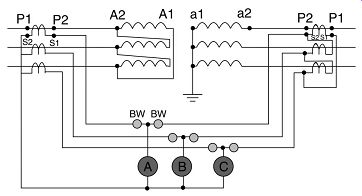
FIG. 48. Typical connections for a delta-star transformer.
Under load or through-fault conditions, the CT secondary currents circulate, passing through the bias windings to stabilize the relay, whilst only small out-of-balance spill currents will flow through the operate coil, not enough to cause operation. In fact the higher the circulating current, the higher will be the spill current required to trip the relay, as can be seen from the following characteristic.
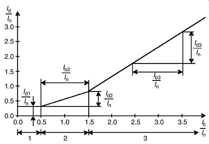
FIG. 49. Operating current of differential relay.
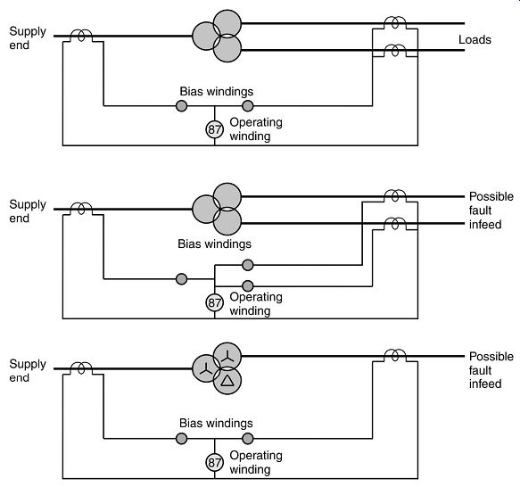
FIG. 50. Biased differential configurations.
Restricted ground fault:
As demonstrated earlier in these notes, a simple overcurrent and ground fault relay won’t provide adequate protection for winding ground faults.
Even with a biased differential relay installed, biasing can cause the relay to become ineffective for certain ground faults within the winding. This is especially so if the transformer is resistance or impedance grounded, where the current available on an internal fault is disproportionately low.
In these circumstances, it’s often necessary to add some form of separate ground fault protection. The degree of ground fault protection is very much improved by the application of unit differential or restricted ground fault systems.
On the HV side, the residual current of the three-line CTs is balanced against the output current of the CT in the neutral conductor, making it stable for all faults outside the zone.
For the LV side, ground faults occurring on the delta winding may also result in a level of fault current of less than full load, especially for a mid-winding fault which will only have half the line voltage applied. The HV overcurrent relays will therefore not provide adequate protection. A relay connected to monitor residual current will provide ground fault protection since the delta winding cannot supply zero-sequence current to the system.
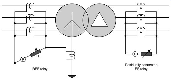
FIG. 51. A restricted ground fault system
The relay used is an instantaneous high-impedance type, the theory of which is shown as follows:
Determination of stability:
The stability of a current balance scheme using a high-impedance relay depends upon the relay voltage setting being greater than the maximum voltage which can appear across the relay for a given through-fault condition.
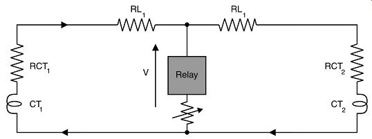
FIG. 52. Basic circuit of high-impedance current balance scheme.
This maximum voltage can be determined by means of a simple calculation, which makes the following assumptions:
• One current transformer is fully saturated, making its excitation impedance negligible.
• The resistance of the secondary winding of the saturated CT together with lead resistance constitute the only burden in parallel with the relay.
• The remaining CTs maintain their ratio.
Referring to the maximum voltage is given:
V = I(Rct + R1)
Where ct ...
CT secondary current corresponding to the maximum steady-state through-fault current
Secondary winding resistance of CT 1
Largest value of lead resistance between relay and current transformer.
For stability, the voltage setting of the relay must be made equal to or exceed the highest value of V calculated above.
Experience has shown that if this method of setting is adopted the stability of the protection will be very much better than calculated. This is because a CT is normally not continuously saturated and consequently any voltage generated will reduce the voltage appearing across the relay circuit.
Method of establishing the value of stabilizing resistor
To give the required voltage setting the high-impedance relay operating level is adjusted by means of an external series resistor as follows: Let v = operating voltage of relay element Let i = operating current of relay equipment and V = maximum voltage as defined under 'determination of stability' above.
It’s sometimes the practice to limit the value of series resistor to say 1000 ohm, and to increase the operating current of the relay by means of a shunt connected resistor, in order to obtain larger values of relay operating voltage.
From the equation above V = I(Rct + R1)
Therefore R1 = (V/I) - Rct
Primary fault setting:
In order for this protection scheme to work it’s necessary to magnetize all current transformers in the scheme plus provide enough current to operate the relay.
Therefore, if = relay operating current , , , = excitation currents of the CT's at the relay setting voltage.
Then the primary fault setting = N(Ir + I1 + I2 + I3 + I4)
In some cases, it may be necessary to increase the basic primary fault setting as calculated above.
If the required increase is small, the relay setting voltage may be increased (if variable settings are available on the relay) which will have the effect of demanding higher magnetization currents from the CT's I1, I2, etc.
Alternatively, or when the required increase is large, connecting a resistor in parallel with the relay will increase the value of I_r.
Current transformer requirements:
Class X CTs are preferably required for this type of protection; however experience has shown that most protection type CTs are suitable for use with high-impedance relays, provided the following basic requirements are met:
• The CTs should have identical turns ratio. Where turns error is unavoidable, it may be necessary to increase the fault setting to cater for this.
• To ensure positive operation, the relay should receive a voltage of twice its setting. The knee-point voltage of the CTs should be at least twice the relay setting voltage (knee-point = 50% increase in mag. Current gives 10% increase in output voltage).
• CTs should be of the low-reactance type.
Protection against excessively high voltages:
As the relay presents a very high impedance to the CTs, the latter are required to develop an extremely high voltage. In order to contain this within acceptable limits, a voltage dependant resistor (VDR), or metrosil, is normally mounted across the relay to prevent external flashovers, especially in polluted environments.
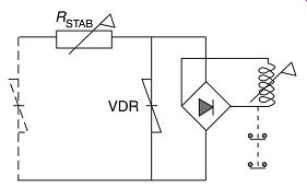
FIG. 53. Protection against excessively high voltages.
Example:
Using FIG. , calculate the setting of the stabilizing resistor for the REF protection.
The relay is 1A rated with 10-40% tappings, burden 1.0 VA. Secondary fault current = 9000
3000 = 30 A
Relay operating current
Choose 10% tap on the relay (10%) = 0.1 A
Relay operating voltage burden 1.0
= = =10 V current 0.1
Stabilizing voltage:
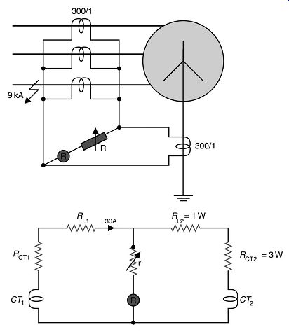
FIG. 54. Example for calculation of setting of stabilizing resistor.
Voltage across stabilizing resistor
Stabilizing voltage relay voltage 120 10 = 110 V
Voltage across resistor; Stabilizing resistance; Current through resistor
Current transformer must therefore have a minimum knee-point voltage of 2 × 120 = 240 V to ensure positive operation of protection for an internal fault.
| Top of Page | PREV: Transformer protection | NEXT: Grounding, earthing and transient overvoltage protection | Index |