AMAZON multi-meters discounts AMAZON oscilloscope discounts
Solid grounding:
The neutral of a power transformer is grounded solidly with a copper conductor.
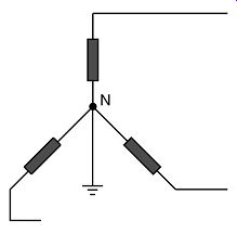
FIG. 1. Solid grounding of power transformer
Advantages:
• Neutral held effectively at ground potential
• Phase-to-ground faults of same magnitude as phase-to-phase faults so no need for special sensitive relays
• Cost of current-limiting device is eliminated
• Size and cost of transformers are reduced by grading insulation toward neutral point N.
Disadvantages:
• As most system faults are phase-to-ground, severe shocks are more consider able than with resistance grounding
• Third harmonics tend to circulate between neutrals.
AMAZON multi-meters discounts AMAZON oscilloscope discountsResistance grounding
A resistor is connected between the transformer neutral and ground.
• Mainly used from 6.6 to 33 kV
• Value is such as to limit an ground fault current to between 1 and 2 times full load rating of the transformer, typically 400A.
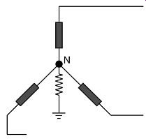
FIG. 2. Resistance grounding
Advantages:
Limits electrical and mechanical stresses on system when an ground fault occurs, but at the same time current is sufficient to operate normal protection equipment.
Disadvantages:
Full line-to-line insulation required between phase and ground.
Reactance grounding:
A reactor is connected between the transformer neutral and ground.
• Values of reactance are approximately the same as used for resistance grounding.
• To achieve the same value as the resistor, the design of the reactor is smaller and thus cheaper.
However, reactance grounding can lead to severe overvoltages during arcing ground faults (see IEEE standard 142). This form of grounding is not recommended.
AMAZON multi-meters discounts AMAZON oscilloscope discounts 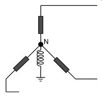
FIG. 3. Reactance grounding
Arc suppression coil (Petersen coil):
A tuneable reactor is connected in the transformer neutral to ground.
• Value of reactance is chosen such that reactance current neutralizes capacitance current. The current at the fault point is therefore theoretically nil and unable to maintain the arc, hence its name.
• Virtually fully insulated system, so current available to operate protective equipment is so small as to be negligible. To offset this, the faulty section can be left in service indefinitely without damage to the system as most faults are ground faults of a transient nature, the initial arc at the fault point is extinguished and does not restrike.
• Sensitive watt-metrical relays are used to detect permanent ground faults.
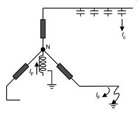
FIG. 4. Arc suppression coil (Petersen coil)
Earthing via neutral electromagnetic coupler with resistor
This type of grounding provides an ground point for a delta system and combines the virtues of resistance and reactance grounding in limiting ground fault current to safe relay-able values. The current should be resistive in nature to comply with IEEE standard 142.
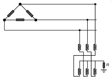
FIG. 5. grounding via neutral grounding compensator
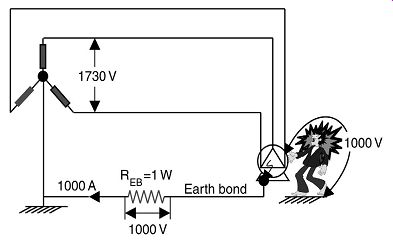
FIG. 6. Touch potentials -- solid grounding
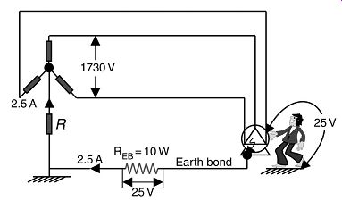
FIG. 7. Touch potentials -- resistive grounding
| Top of Page | PREV: Transformer Protection Relays | NEXT: Electric shock and human beings | Index |