AMAZON multi-meters discounts AMAZON oscilloscope discounts
The block diagram for the control system shown in ill. 1 (below) is called a loop because a sensor is used to sample the temperature and send its PV signal from its sensor back to the summing junction where it can be compared to the SP. The sensor signal is also called the feedback signal because it gets fed back to the summing junction. When this happens, it's called closing the loop, and the system is called a closed-loop system.
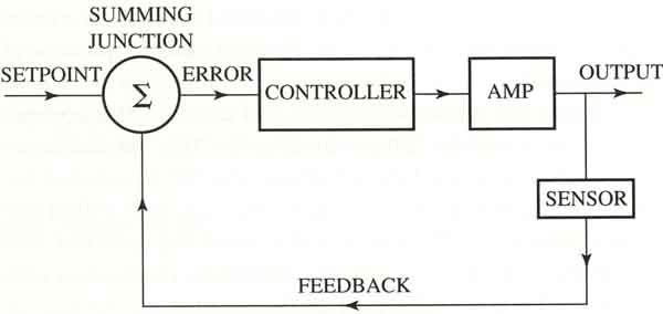
If the feedback signal isn't used, the system is called an open-loop system. Inmost systems it's possible to use a switch to control the PV (sensor) signal that's used for feedback. If the switch is closed, the sensor signal is used as feedback, and if the switch is open, the sensor signal isn't used. This switch is used to determine if the loop is operated in open-loop or closed-loop mode. When the system is in open-loop mode, the output is adjusted manually by the operator. E.g., in the paint-drying oven, the operator can set the output signal to 50%, which will provide 50% full energy to the heating element. The actual amount of heat the elements provide must be observed by the operator and the operator must decide if temperature adjustments are necessary. The drying oven is usually placed in open loop during the warm-up period for the oven or during system troubleshooting or calibration.
It's also important to understand at this point that the sensor signal has several names that are used interchangeably. These names are process variable (PV) signal, feedback signal, and sensor signal. One important distinction should be made at this time. The process variable is the temperature that's being changed, and the process variable (PV) signal is the signal that comes from the thermocouple that indicates what the temperature is.
Servo system is a name given to a wide variety of control systems that use feedback. These systems can usually be broken into the two broad categories of motion control and process control. Motion control servo systems can use linear motion devices such as a rack and pinion or a ball screw to provide linear motion, and they can use servomotors and gears to provide circular motion. Motion control systems are usually associated with robots, machine tools, and variable-speed motor drive applications. These types of systems will be covered in depth in a later section. This section will primarily use process control systems as examples because they are easy to visualize. Typical industrial process control systems such as controlling temperature and liquid levels will be used extensively in this section.
PREV: Example from Automotive Industry
NEXT: Manual Mode and Auto Mode