AMAZON multi-meters discounts AMAZON oscilloscope discounts
Accurate oscilloscope measurements require that you make sure your system is properly setup each time you begin to use your scope.
Compensating the Probe
Most measurements you make with an oscilloscope require an attenuator probe, which is any probe that reduces voltage. The most common are lox (“times ten”) passive probes which re duce the amplitude of the signal and the circuit loading by 10:1.
But before you make any measurement with an attenuator probe, you should make sure it’s compensated. Figure 23 illustrates what can happen to the waveforms you’ll see when the probe is not properly corn pen- sated.
Note that you should compensate your probe as it will be used when you make the measurement. Compensate it with the accessory tip you’ll be using and don’t compensate the probe in one vertical channel and then use it on another.
AMAZON multi-meters discounts AMAZON oscilloscope discounts
Checking the Controls
The most common mistake in making oscilloscope measurements is forgetting to compensate the probe. The second most frequent source of inaccuracies is forgetting to check the controls to make sure they’re where you think they are. Here are some things to check on your Tektronix 2200 Series scope (arranged according to the functional blocks of your scope):
- Check all the vertical system controls: variable controls (CH 1 and CH 2 VOLTS/DIV CAL) should be in their calibrated de tent positions; make sure CH 2 isn’t inverted (unless you want it to be); check the vertical mode switches to make sure the signal from the proper channel(s) will be displayed; check the two vertical system VOLTS/DIV switches to see if their settings are right (and don’t forget to use the VOLTS/DIV readout that matches the probe, either 1x or 10X); check the input coupling levers too.
- Check the horizontal system control settings; magnification is off (push in the red CAL switch in the middle of the SEC/DIV switch); variable SEC/DIV is in its calibrated de tent position. Make sure the horizontal mode switch is where you need it. NO DLY when you’re not making delayed sweep measurements, INTENS for making measurements with an intensified zone, or DLY’D if you want a delayed sweep (A, ALT, or B on a 221 5A).
- Then check your trigger system controls to make sure your scope will pick the right slope on the trigger signal, that the right coupling is selected, and that the correct operating mode will be used. Also make sure that the trigger variable holdoff control is at its mini mum position.
Handling a Probe
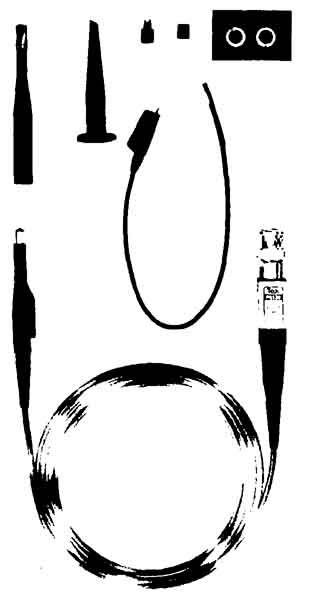
Before you probe a circuit, you should make sure you have the right probe tips and adaptors for the circuits you will be working on. (Tips available for the Tektronix P6122 10X probes were shown in Figure 14, Section 5.)
Then make sure that the ground in the circuit-under-test is the same as the scope ground — don’t just assume it's . The scope ground will always be earth ground as long as you’re using the proper power cord and plug. Check the circuit ground by touching the probe tip to the point you think is ground before you make a hard ground by attaching the ground strap of your probe.
If you’re going to be probing a lot of different points in the same circuit and measuring frequencies less than 5 MHz, you can ground that circuit to your scope once instead of each time you move the probe. Connect the circuit ground to the jack marked GND on the front panel.
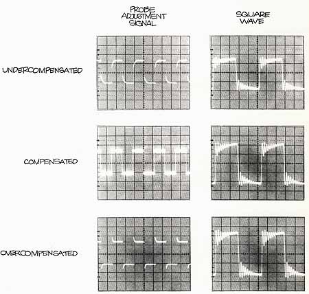
Figure 23. IMPROPERLY COMPENSATED PROBES can distort the waveforms you
see on the screen of your scope. In the photographs the probe adjustment
signal and a 1 MHz square wave are shown as they will appear with proper and improper compensations. Notice the amplitude and ringing changes on
the square wave with the differences in compensation.