AMAZON multi-meters discounts AMAZON oscilloscope discounts
The preferred vibration isolation (i.e., type of isolator, static deflection of isolator, mounting support of equipment) for mechanical equipment depends on several factors. The major ones are the operating characteristics of the equipment, the location of the equipment (e.g., on-grade or on upper floors above sensitive areas), and the floor span of the structural system. Longer floor spans generally require vibration isolators with larger deflections. The sections below present basic guidelines for vibration isolation for a variety of mechanical equipment that designers may encounter in comfort systems for buildings.
Fans
Large centrifugal fans can be a source of considerable noise and low- frequency vibration. For example, for a given fan-operating efficiency, a doubling of static pressure increases noise by 6 dB and a doubling of airflow volume increases noise by 3 dB.
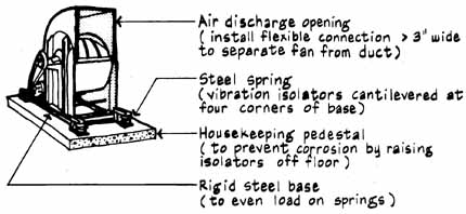
To avoid misalignment, which can wear out fan belts and bearings, large fans and their motors should be mounted on a common rigid steel base which in turn should be supported by widely separated, unhoused (or open) spring isolators. The bases should have their longer dimension oriented in the direction of the airflow. For sensitive locations, install fans on an inertia block mounted on open-coil steel springs. An inertia block is a concrete slab base two to three times the weight of the fan assembly. It provides rigid support, maintains proper alignment between connected components of the vibrating equipment, reduces start-up motion, and evens out the load on the springs. The open-coil steel springs, sized for horizontal stability, don't bind or short- circuit like metal-housed springs. In completed installations, check to assure that springs are not totally seated and neoprene pads not underloaded. For many fan assemblies with effective soft supports, you actually should be able to rock the rigid base (see FAN ROOM TREATMENT for additional isolation details).
Both supply and return air ducts should contain flexible canvas, rubber, or loaded vinyl connections ( > 3-in separation) to break the vibration path and permit start-up motion. For sensitive locations, air ducts should be resiliently supported as shown below. In addition, all pipe and conduit connections to the fan assembly should be flexible or suspended by isolation hangers.
Centrifugal Fan
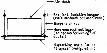
Resiliently Supported Air Duct
Refrigeration Compressors
Large, low-speed reciprocating compressors should be isolated by springs and inertia blocks to reduce the amplitude of the vibrations. High-speed centrifugal compressors require less isolation. They may require isolation by springs but often can be isolated properly with several layers of ribbed neoprene.
aa-284-2.jpg Compressors: Open and hermetic reciprocating compressor; Inertia block concrete base; housekeeping pedestal; Vibration isolator
Note: The inertia block should weigh more than twice as much as the vibrating equipment and associated pipes, ducts, and conduit when used to support fans (> 60 hp); reciprocating pumps, compressors, and engines; or centrifugal pumps and compressors (>3 hp).
Boilers
The combustion air blower usually is the primary source of noise and low- frequency vibration from boilers. Most airborne noise is radiated from the front face of the unit and from the air and fuel supply paths (i.e., combustion rumble). Install a flexible connection in the exhaust breeching (smoke vent) between boiler and exhaust stack. For boilers on upper floors near critical areas, use a steel mounting frame which in turn is supported by neoprene-in- shear mounts or steel springs. Gas and electrical connections should have long, “floppy” sections of braided flexible tubing and flexible armored electrical conduit.
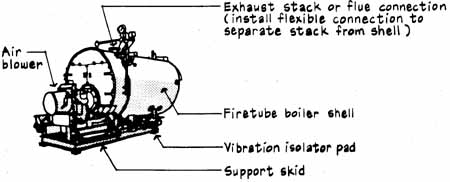
Forced-Draft Boiler: Fire-tube boiler shell; Support
skid; etc.
Cooling Towers
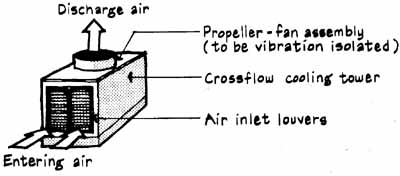
Cooling tower vibration involves low-frequency vibration of the relatively slow-turning propeller-type fans as well as high-frequency impact noise from falling water. Ideally the motor, drive shaft, gear reducer, and propeller should be rigidly supported, with this support element in turn resiliently isolated from the tower. However, the more common noise control technique for roof- mounted cooling towers is to support the entire cooling tower by large- deflection steel springs and ribbed neoprene mounts.
To prevent airborne noise problems, locate ground-level cooling towers a considerable distance from buildings. Mufflers can be used to control airborne noise from cooling towers if the muffler attachments are carefully sized so that additional pressure drops will be low.
Induced-Draft Cooling Tower
Transformers
In or near buildings, where structure-borne sound could be objectionable, dry-type transformers should be isolated by several layers of waffle-shaped or ribbed neoprene (40 to 50 durometer), precompressed glass fiber, or steel springs. All electrical connections should be flexible braided cable, and conduit should have a full 360° loop or manufactured flexible joints. Partial or de mountable enclosures, lined with sound-absorbing materials, also can be used to help isolate annoying humming noises.
For indoor locations, use volume resonators to absorb low-frequency sound energy (about 125 Hz). Avoid upper-floor locations for dry-type trans formers. These locations don't provide the rigid support that can be achieved on grade or at basement locations. To prevent noise buildup by standing waves, install the transformer so its sides are not parallel to the walls of small equipment rooms (slope >10°). Standing waves (normally heard as “booming” sound) are due to the superposition, or buildup, of low-frequency sound waves reflected between parallel wall surfaces.
For a summary of isolation techniques, see I. L. Vér et al., “Barrier-Enclosure: An Effective Way to Control the Noise Emission of Power Trans formers,” Proceedings of the 1981 National Conference on Noise Control Engineering, Noise Control Foundation, Poughkeepsie, N.Y., 1981, pp. 65-68.
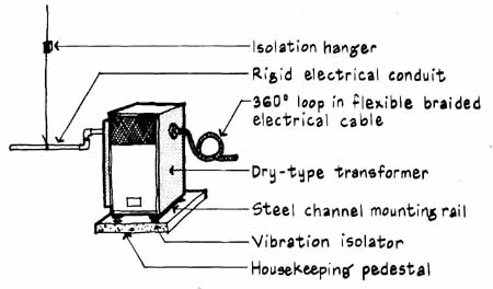
Transformer
Next: Characteristics of Duct System Noise
Prev: Rubber Mounts