AMAZON multi-meters discounts AMAZON oscilloscope discounts
This section details and discusses the options available for monitoring various contaminants.
It includes information for contaminant mixes, thermal enthalpy, interferences, and basis calibration. It also provides cross-section diagrams to illustrate the internal function of various detector and sensor elements.
1. VOLATILE ORGANIC COMPOUNDS
Sampling for volatile organics essentially means sampling for carbon-containing com pounds that can get into the air. The term volatile usually means that the chemical gets into the air through a change of phase from liquid to gas. This phase change occurs when temperatures approach, equal, and exceed the boiling point and continue until equilibrium is established in the environment.
For a chemical with a boiling point over 100°F, we would not expect to find that chemical volatilizing at room temperatures. A chemical with a boiling point of 75°F, on the other hand, would be expected to readily volatilize into the environment.
Unfortunately, like so many rules, this one is not always true. Volatilization can imply that the chemical is being transported in the airstream by mechanical means that exposes surface area. An example of this anomaly is mercury, which has a boiling point of 674°F.
Mercury as a liquid can be dispersed into the airstream as tiny droplets. The phase change occurs around each of these droplets as an equilibrium is established between the mercury liquid and the mercury in the immediate area gas phase. Thus mercury vapor is dispersed into the atmosphere by an equilibrium volatilization phenomenon that is more dependent on mechanical dispersion than on temperature differentials.
FIG. 1 Photoionization detector working diagram. (from RAE
Systems)
1.1 Photoionization Detector (PID)
Some volatile chemicals can be ionized using light energy. Ionization is based on the creation of electrically charged atoms or molecules and the flow of these positively charged particles toward an electrode. Photoionization ( FIG. 1) is accomplished by applying the energy from an ultraviolet (UV) lamp to a molecule to promote this ionization. APID is an instrument that measures the total concentration of various organic vapors the in the air.
Molecules are given an ionization potential (IP) number based on the energy needed to molecularly rip them apart as ions. Chemicals normally found in the solid and liquid state at room temperatures don’t have an IP. By definition IPs are given to chemicals found at room temperature as gases (FIG. 2).
If the IP is higher than the energy that can be transmitted to a molecule by the UV lamp, the molecule won’t break apart. Other energy sources can be used from other instruments, such as the flame ionization detector (FID) that has a hydrogen gas flame to impart energy to molecules; of course, these detectors are not called PIDs.
The PID is a screening instrument used to measure a wide variety of organic and some inorganic compounds. The PID's limit of detection for most volatile contaminants is approximately 0.1 ppm. The instrument ( FIG. 3) has a handheld probe. The specificity of the instrument depends on the sensitivity of the detector to the substance being measured, the number of interfering compounds present, and the concentration of the sub stance being measured relative to any interferences.
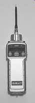
FIG. 3 Photoionization detector with a 10.6 eV detector. (from RAE
Systems)
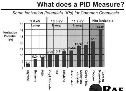
FIG. 2 Ionization potentials. (from RAE
Systems)
Newer PIDs have sensitivities down to the parts per billion range. These instruments utilize very high-energy ionization lamps. When toxic effects can occur at the parts per billion range, such as with chemical warfare agents or their dilute cousins-pesticides and other highly hazardous chemicals-these newer PIDs are essential (FIG. 4).
Some PIDs are FM approved to meet the safety requirements of Class 1, Division 2, hazardous locations of the National Electrical Code.
FIG. 4 Portable VOC monitor with parts per billion detection.
Honeywell Analytics IAQPoint2 ABS Touchscreen Analog VOC IAQ Monitor, Wall Mount, Relay, Display, 0-100 Measuring Range
(other suggested VOC monitors)

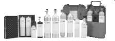
FIG. 5 Calibration gases.(suggested calibration gases)
1.1.1 Calibration
An instrument is calibrated by introducing pressurized gas with a known organic vapor concentration from a cylinder into the detector housing. Once the reading has stabilized, the display of the instrument is adjusted to match the known concentration. A calibration of this type is performed each day prior to using the PID ( FIG. 5).
If the output differs greatly from the known concentration of the calibration gas, the initial procedure to remedy the problem is a thorough cleaning of the instrument. The cleaning process normally removes foreign materials (i.e., dust, moisture) that affect the calibration of the instrument. If this procedure does not rectify the problem, further troubleshooting is performed until the problem is resolved. If field personnel cannot resolve the problem, the instrument is returned to the manufacturer for repair, and a replacement unit is shipped to the site immediately. The manufacturer's manual must accompany the instrument.
The PID must be kept clean for accurate operation. All connection cords used should not be wound tightly and are inspected visually for integrity before going into the field. A battery check indicator is included on the equipment and is checked prior to going into the field and prior to use. The batteries are fully charged each night. The PID should be packed securely and handled carefully to minimize the risk of damage.
A rapid procedure for calibration involves bringing the probe close to the calibration gas and checking the instrument reading. For precise analyses it’s necessary to calibrate the instrument with the specific compound of interest. The calibration gas should be pre pared in air.
1.1.2 Maintenance
Keeping an instrument in top operating shape means charging the battery, cleaning the UV lamp window and light source, and replacing the dust filter. The exterior of the instrument can be wiped clean with a damp cloth and mild detergent if necessary. Keep the cloth away from the sample inlet, however, and don’t attempt to clean the instrument while it’s connected to an electrical power source.
FIG. 6 An infrared gas monitor measures carbon dioxide and sends a signal
to the ventilation control system.
(suggested infrared gas monitors)
1.2 Infrared Analyzers
The infrared analyzer can be used as a screening tool for a number of gases and vapors and is presently recommended by OSHA as a screening method for substances with no feasible sampling and analytical method ( FIG. 6). These analyzers are often factory programmed to measure many gases and are also user programmable to measure other gases.
A microprocessor automatically controls the spectrometer, averages the measurement signal, and calculates absorbance values. Analysis results can be displayed either in parts per million or absorbance units (AU). The variable path-length gas cell gives the analyzer the capability of measuring concentration levels from below 1 ppm up to percent levels.
Some typical screening applications are as follows:
• Carbon monoxide and carbon dioxide, especially useful for indoor air assessments
• Anesthetic gases, e.g., nitrous oxide, halothane, enflurane, penthrane, and iso-flurane
• Ethylene oxide
• Fumigants, e.g., ethylene dibromide, chloropicrin, and methyl bromide
The infrared analyzer may be only semi-specific for sampling some gases and vapors because of interference from other chemicals with similar absorption wavelengths.
1.2.1 Calibration
The analyzer and any strip-chart recorder should be calibrated before and after each use in accordance with the manufacturer's instructions.
1.2.2 Maintenance
No field maintenance of this device should be attempted except for items specifically detailed in the instruction book, such as filter replacement and battery charging.
1.3 Remote Collection
Various containers may be used to collect gases for later release into laboratory analytical chambers or sorbent beds. The remote collection devices include bags ( FIG. 7), canisters ( FIG. 8), and evacuation chambers. Remote collection refers to the practice of collecting the gas sample, hopefully intact, at a site remote from the laboratory where analysis will occur.
This method of sample collection must always take into account the potential of the collecting vehicle reacting with the gaseous component collected during the time between collection and analysis. For this reason various plastic formulations and stainless steel compartments have been devised to minimize reactions with the collected gases.
When bags are used, the fittings for the bags to the pumps must be relatively inert and are usually stainless steel ( FIG. 9). Multiple bags may be collected and then applied to a gas chromatograph (GC) column using multiple bag injector systems ( FIG. 10).
One innovation in remote sampling of this type is the MiniCan. This device can be preset to draw in a known volume of gas. The MiniCan is then worn by a worker or placed in a static location. Sample collection then occurs without the use of an additional air sampling pump ( FIG. 11).
1.4 Oxygen/Combustible Gas Indicators (O2/CGIs)/Toxin Sensors
To measure the lower explosive limit (LEL) of various gases and vapors, these instruments use a platinum element or wire as an oxidizing catalyst. The platinum element is one leg of a Wheatstone bridge circuit. These meters measure gas concentration as a percentage of the LEL of the calibrated gas ( FIG. 12).
FIG. 7 Gas sample bags are a convenient means of collecting gas and vapor
samples in air. (SKC)
(suggested Gas sample bag)
FIG. 8 Six-liter canisters can be used for the passive collection of ambient
VOCs from 0.1 to 100 ppb over a period of time. (SKC)
The oxygen meter displays the concentration of oxygen in percent by volume measured with a galvanic cell. Some O2/CGIs also contain sensors to monitor toxic gases/ vapors. These sensors are also electrochemical (as is the oxygen sensor). Thus, whenever the sensors are exposed to the target toxins, the sensors are activated.
Other electrochemical sensors are available to measure carbon monoxide (CO), hydro gen sulfide (H2S), and other toxic gases. The addition of two toxin sensors, one for H2S and one for CO, is often used to provide information about the two most likely contaminants of concern, especially within confined spaces. Since H S and CO are heavier than ambient air (i.e., the vapor pressure of H2S is greater than one), the monitor or the monitor's probe must be lowered toward the lower surface of the space/area being monitored.
Other toxic sensors are available; all are electrochemical. Examples are sensors for ammonia, carbon dioxide, and hydrogen cyanide. These sensors may be installed for special needs.
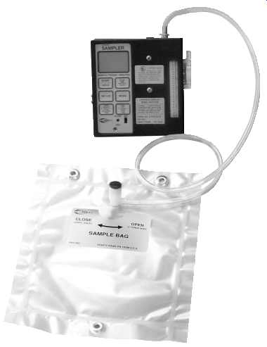
FIG. 9 Air sampling pump connected to a Tedlar Bag. (SKC)
1.4.1 Remote Probes and Diffusion Grids
With a remote probe, air sampling can be accomplished without lowering the entire instrument into the atmosphere. Thus, both the instrument and the person doing the sampling are protected. The remote probe has an airline (up to 50 ft) that draws sampled air toward the sensors with the assistance of a powered piggyback pump. Without this arrangement the O2/CGI monitor relies on a diffusion grid (passive sampling).
All O2/CGIs must be positioned so that either the diffusion grids over the sensors or the inlet port for the pumps are not obstructed. For instance, don’t place the O2/CGI on your belt with the diffusion grids facing toward your body.
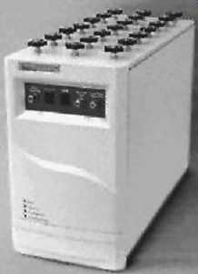
FIG. 10 The Tedlar Bag Autosampler automates the introduction of up to
21 samples into a GC for quantitative analysis. (Entech Instruments Inc.)
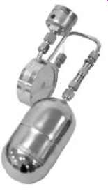
FIG. 11 Stainless steel canisters are used for collecting air samples of
VOCs and sulfur com pounds over a wide concentration range (1 ppb to 10,000
ppm). This 400-cc unit can be placed at a sampling site for area sampling
or attached onto a worker's belt for personal sampling. (SKC-MiniCans)
Multigas meters
FIG. 12 Multigas meters are available to allow the user to select as many
as five sensors that can be used at one time. Shown above is: Multi-Gas Detector, 4 Gas, -4 to 122F, LCD
(other suggested multigas meters)
1.4.2 Calibration Alert and Documentation
A calibration alert is available with most O2/CGIs to ensure that the instruments cannot be used when factory calibration is needed. Fresh air calibration and sensor exposure gas calibration for LEL levels and toxins can be done in the field. However, at approximately 6-12 month intervals, and whenever sensors are changed, factory calibration is required to ensure that electrical signaling is accurate.
Always calibrate and keep calibration logs as recommended by the manufacturer. In lieu of the manufacturer's recommendations, O2/CGIs must be calibrated at least every 30 days.
If O2/CGIs are transported to higher elevations (i.e., from Omaha to Denver) or if they are shipped in an unpressurized baggage compartment, recalibration may be necessary.
Refer to the manufacturer's recommendations in these cases.
1.4.3 Alarms
Alarms must be visible and audible, with no opportunity to override the alarm command sequence once initiated and while still in the contaminated alarm-initiating environment. The alarm can be enhanced up to 150 dBA. The alarm must be wired so that the alarm signal cannot be overridden by calibration in a contaminated environment and thus cease to provide valid information.
An audible alarm that warns of low oxygen levels or malfunction or an automatic shutdown feature is very important because without adequate oxygen, the CGI won’t work correctly.
1.4.4 Recommendations for O2/CGIs
At a minimum, all O2/CGIs must contain sensors for detecting levels of oxygen and the LEL percentage of the vapors/gases in the area. In an oxygen-depleted or oxygen-enriched environment, the LEL sensor will burn differently (slower in an oxygen-depleted environment and faster in an oxygen-enriched environment). Thus, in an oxygen-depleted environment the LEL sensor will be slower to reach the burn rate the monitor associates with 10% of the LEL of the calibration gas and vice versa. Consequently, all O2/CGIs must monitor and alarm first on the basis of the oxygen level, then in response to LEL or toxin levels.
• The oxygen monitor must be set to alarm at less than 19.5% oxygen (oxygen depleted atmosphere, hazard of asphyxiation) and greater than 22% oxygen (oxygen-enriched atmosphere, hazard of explosion/flame). Note: The confined space regulation for industry (29 CFR 1910.146) defines an oxygen-enriched atmosphere at greater than 23.5% oxygen.
• The LEL must be set to alarm at 10% in confined space entries.
This alarm should be both audible and visible. The alarm should not reset automatically. In other words, a separate action on the part of the user should be required to reset the alarm.
The oxygen sensor is an electrochemical sensor that will degrade as the sensor is exposed to oxygen. Thus, whether the sensor is used or not, the oxygen sensor will degrade in a period of 6 to 12 months.
Some manufacturers recommend storing the monitor in a bag placed in a refrigerated compartment. This procedure has minimal value. Because the oxygen sensor is constantly exposed to oxygen and will degrade (regardless of usage), O2/CGIs should be used often and continuously-"there is no saving them!'' In other words, once the O2/CGI is turned on, leave the O2/CGI on. Don’t turn the monitor "on and off.
1.4.5 Relative Response
When using O2/CGIs to monitor the LEL, remember that calibration to a known standard is necessary; all responses to any other gases/vapors will be relative to this calibration standard. Thus, if the O2/CGI is calibrated to pentane (five-carbon chain), the response to methane (one-carbon chain) will be faster. In other words, less of the methane will be necessary in order for the monitor to show 10% of the LEL than if the sensor was exposed to pentane.
The LEL sensor is a platinum wire/filament located on one side of a Wheatstone bridge electrical circuit. As the wire is exposed to gases/vapors, the burn rate of the filament is altered. Thus, the resistance of the filament side of the Wheatstone bridge is changed. The O2/CGI measures this change in resistance.
• The LEL sensor functions only when the O2/CGI is in use; therefore, some manufacturers will state that usage of the O2/CGI accelerates the breakdown of this sensor. However, because the oxygen sensor is much more susceptible to degradation regardless of usage, turning the monitors on and off just to preserve the LEL sensor is not recommended.
• Remember that the LEL readout is a percentage of the LEL listed for each chemical. Thus, if the LEL for a particular calibration gas is 2%, at 10% of the LEL, 0.2% of the calibration gas is present. This comparison is not possible for other than the calibrated gas/vapor atmospheres. As an example, when an O2/CGI is calibrated to pentane and then taken into an unknown atmosphere, then at 10% of the LEL, the sensor's burn rate is the same as if the sensor had been exposed to 10% of the LEL for pentane.
If atmospheres of methane or acetylene are known to be present, the O2/CGI must be calibrated for these gases.
1.4.6 Relative Response and Toxic Atmosphere Data
No direct correlation can be made under field conditions between the LEL monitor and the level of toxins. Thus, 10% (1 _ 10^2 ) LEL readings cannot be converted to parts per mil lion (ppm, 1 _ 10^6 ) by simply multiplying by 10,000. In a controlled laboratory atmosphere using only the atmosphere to which the CGIs were calibrated, and then using many trials of differing atmospheres, relative monitoring responses and correlation to toxin levels may be obtained. However, in the field, and particularly in relatively unknown constituent atmospheres, such correlations cannot be made.
1.4.7 Special Considerations
• Silicone compound vapors, leaded gasoline, and sulfur compounds will cause desensitization of the combustible sensor and produce erroneous (low) readings.
• High relative humidity (90-100%) causes hydroxylation, which reduces sensitivity and causes erratic behavior, including inability to calibrate.
• Oxygen deficiency or enrichment such as in steam or inert atmospheres will cause erroneous readings for combustible gases.
• In drying ovens or unusually hot locations, solvent vapors with high boiling points may condense in the sampling lines and produce erroneous (low) readings.
• High concentrations of chlorinated hydrocarbons such as trichloroethylene or acid gases such as sulfur dioxide will depress the meter reading in the presence of a high concentration of combustible gas.
• High-molecular-weight alcohols can burn out the meter's filaments.
• If the flash point is greater than the ambient temperature, an erroneous (low) concentration is indicated. If the closed vessel is then heated by welding or cutting, the vapors will increase, and the atmosphere may become explosive.
• For gases and vapors other than those for which a device was calibrated, users should consult the manufacturer's instructions and correction curves.
1.4.8 Calibration
Before using the monitor each day, calibrate the instrument to a known concentration of combustible gas (usually methane) equivalent to 25-50% LEL full-scale concentration.
The monitor must be calibrated to the altitude at which it’s used. Changes in total atmospheric pressure due to changes in altitude will influence the instrument's measurement of the air's oxygen content. The instrument must measure both the level of oxygen in the atmosphere and the level a combustible gas reaches before igniting; consequently, the calibration of the instrument is a two-step process.
1. The oxygen portion of the instrument is calibrated by placing the meter in normal atmospheric air and determining that the oxygen meter reads exactly 20.8% oxy gen. This calibration should be done once per day when the instrument is in use.
2. The CGI is calibrated to pentane to indicate directly the percentage LEL of pentane in air. The CGI detector is also calibrated daily when used during sampling events and whenever the detector filament is replaced. The calibration kit included with the CGI contains a calibration gas cylinder, a flow control, and an adapter hose.
The unit's instruction manual provides additional details on sensor calibration.
1.4.9 Maintenance
The instrument requires no short-term maintenance other than regular calibration and battery recharging. Use a soft cloth to wipe dirt, oil, moisture, or foreign material from the instrument. Check the bridge sensors periodically, at least every 6 months, for proper functioning.
1.5 Oxygen Meters
Oxygen-measuring devices can include coulometric and fluorescence measurement, paramagnetic analysis, and polarographic methods.
1.6 Solid Sorbent Tubes
Organic vapors and gases may be collected on activated charcoal, silica gel, or other adsorption tubes using low-flow pumps. Tubes may be furnished with either caps or flame-sealed glass ends. If using the capped version, simply uncap during the sampling period and recap at the end of the sampling period.
Multiple tubes can be collected using one pump. Flow regulation for each tube is accomplished using critical orifices and valved regulation of airflow. Calibration of parallel or y-connected multiple tube drawing stations must be done individually for each tube, even in cases where the pump is drawing air through more than one tube in a parallel series (FIG. 13). In instances where tubes are connected in series, only one calibration draw is done through the conjoined tubes that empty air, one directly into the other ( FIG. 14).
Sorbent tubes may be used just to collect gases and vapors or to both collect and react with the collected chemicals. Some of the reactions may produce chemicals that when off gassed could harm the pumps being used to pull air through the sorbent media bed. In these cases either filters or intermediate traps must be used to protect the pumps ( FIG. 15). The following protocols should be followed:
• Immediately before sampling, break off the ends of the flame-sealed tube to pro vide an opening approximately half the internal diameter of the tube. Take care when breaking these tubes-shattering may occur. A tube-breaking device that shields the sampler should be used.
• Wear eye protection.
• Use tube holders, if available, to minimize the hazards of broken glass ( FIG. 16).
• Don’t use the charging inlet or the exhaust outlet of the pump to break the ends of the tubes.
• Use the smaller section of the tube as a backup and position it near the sampling pump.
• The tube should be held or attached in an approximately vertical position with the inlet either up or down during sampling ( FIG. 17).
• Draw the air to be sampled directly into the inlet of the tube. This air is not to be passed through any hose or tubing before entering the tube. A short length of protective tape, a tube holder, or a short length of tubing should be placed on the cut tube end to protect the worker from the jagged glass edges.
• Cap the tube with the supplied plastic caps immediately after sampling and seal as soon as possible.
• Don’t ship the tubes with bulk material.
For organic vapors and gases, low-flow pumps are required. With sorbent tubes, flow rates may have to be lowered or smaller air volumes (half the maximum) used when there is high humidity (above 90%) in the sampling area or when relatively high concentrations of other organic vapors are present.
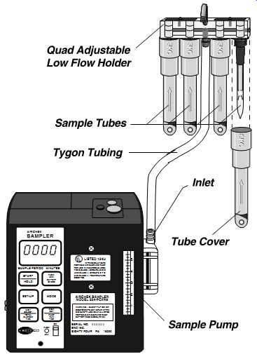
FIG. 13 Multi-tube sampling allows sampling of multiple contaminants requiring
different sampling tubes with one pump. Multitube sampling also allows
you to collect time weighted averages (TWAs) and short-term exposure limits
(STELs) side by side. (SKC)
1.6.1 Calibration Procedures
Set up the calibration apparatus as shown in FIG. 18, replacing the cassette and cyclone with the solid sorbent tube to be used in the sampling (e.g., charcoal, silica gel, other sorbent media). If a sampling protocol requires the use of two sorbent tubes, the calibration train must include these two tubes. The airflow must be in the direction of the arrow on the tube ( FIG. 19). Sorbent tubes may be difficult to calibrate, especially if flow-restrictive devices must be used ( FIG. 20).
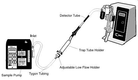
FIG. 14 Pump with detector tube sampling train with calibrator. (SKC-pump,
low-flow holder, trap tube holder, and electronic calibrator)
FIG. 15 Pump with detector tube sampling train in place. Chemicals may
be generated that, if allowed to enter the sampler, could damage the sampler.
Therefore, a trap tube must be used between the detector tube and the
sampler. (SKC-pump, low-flow holder, and trap tube holder)
FIG. 16 Worker wearing sampling pump with sampling train in place in breathing
zone. (SKC- 210 Series Pocket Pump®, low flow tube holder)
1.7 Vapor Badges
Passive-diffusion sorbent badges are useful for screening and monitoring certain chemical exposures, especially vapors and gases ( FIG. 21). Badges are available from the laboratory to detect mercury, nitrous oxide, ethylene oxide, and formaldehyde ( FIG. 22). Interfering substances should be noted.
A variation on the vapor badge is available as a dermal patch ( FIG. 23). These dermal patches can also be used in the detection of semivolatiles.
1.8 Detector Tubes
Detector tubes use the same medium base-silica gel or activated charcoal-as do many sorbent tubes. The difference is that the detector tubes change color in accordance with the amount of chemical reaction occurring within the medium base. The medium base has been treated with a chemical that effects a given color change when certain chemicals are introduced into the tube and reside for a time in the medium. The residence time for the reaction to occur and the volume of air that must be drawn through the detector tubes varies with the chemical and anticipated concentration. All detector tube manufacturers supply the recipe for using their detector tubes as an insert sheet with the tubes.

FIG. 17 Sorbent tube placement with protective tube holder. (SKC)
FIG. 18 Cassette and cyclone use.
Detector tube pumps are portable equipment that, when used with a variety of commercially available detector tubes, are capable of measuring the concentrations of a wide variety of compounds in industrial atmospheres. Each pump should be leak-tested before use. Calibrate the detector tube pump for proper volume at least quarterly or after 100 tubes.
Operation consists of using the pump to draw a known volume of air through a detector tube designed to measure the concentration of the substance of interest. The concentration is then determined by a colorimetric change of an indicator that is present in the tube contents ( FIG. 24).
Most detector tubes can be obtained locally. Draeger or Sensidyne tubes are specified by some employers; their concentration detection ranges match employers' needs.
Detector tubes and pumps are screening instruments that may be used to measure more than 200 organic and inorganic gases and vapors or for leak detection. Some aerosols can also be measured.
Detector tubes of a given brand should be used only with a pump of the same brand.
The tubes are calibrated specifically for the same brand of pump and may give erroneous results if used with a pump of another brand.
A limitation of many detector tubes is the lack of specificity. Many indicators are not highly selective and can cross-react with other compounds. Manufacturers' manuals describe the effects of interfering contaminants.
FIG. 19 Tube sampling train connected to a sample pump and a flowmeter.
(SKC-PCXR8 Sampler and Film Flowmeter)
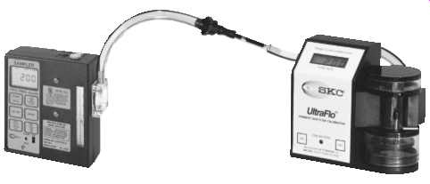
FIG. 20 Electronic flowmeter connected to sorbent tube sampling train.
(SKC-Model 709 Flowmeter)
Another important consideration is sampling time. Detector tubes give only an instantaneous interpretation of environmental hazards, which may be beneficial in potentially dangerous situations or when ceiling exposure determinations are sufficient. When long term assessment of occupational environments is necessary, short-term detector-tube measurements may not reflect TWA levels of the hazardous substances present.
Detector tubes normally have a shelf life at 25°C of 1 to 2 years. Refrigeration during storage lengthens the shelf life. Outdated detector tubes (i.e., beyond the printed expiration date) should never be used.
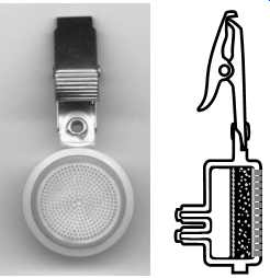
FIG. 21 Cross-sectional view of a passive sampler. A diffusion barrier
maintains sample uptake by molecular diffusion independent of wind velocity.
(SKC-575 Series Passive Sampler)
FIG. 22 Passive badge sampler. (SKC-Formaldehyde Passive Sampler)
FIG. 23 Dermal polyurethane foam (PUF) patches for chlorinated or organo-nitrogen herbicides. The dermal patches are clipped onto a worker's clothing or taped to the skin in various locations where absorption may occur. After sampling, the patches are transferred to glass jars, desorbed with isopropanol, and analyzed by gas chromatography/electron capture detection (GC/ECD). (SKC)
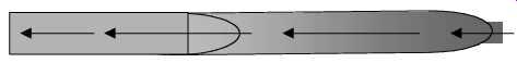
FIG. 24 Sorbent tube of detector tube. Flow is toward the air sampling
pump in the direction of the arrow.
1.8.1 Performance Data
Specific models of detector tubes can be obtained from the manufacturer (e.g., Draeger, Sensidyne). The specific tubes listed are designed to cover a concentration range that is near the permissible exposure limit (PEL). Concentration ranges are tube dependent and can be anywhere from one hundredth to several thousand parts per million. The limits of detection depend on the particular detector tube. Accuracy ranges vary with each detector tube.
The pump may be handheld during operation (weight about 8-11 oz), or it may be an automatic type (weight about 4 lb) that collects a sample using a preset number of pump strokes. A full pump stroke for either type of short-term pump has a volume of about 100 ml.
In most cases where only one pump stroke is required, sampling time is about 1 min.
Determinations for when more pump strokes are required take proportionately longer.
Multiple tubes can be used with newer microcapillary detector tube instruments.
Computer chips are programmed to draw preselected air volumes across these detector tubes. Readout is measured based on changes in light absorption across the microcapillary tubes.
1.8.2 Leakage Test
Each day prior to use, perform a pump leakage test by inserting an unopened detector tube into the pump and attempt to draw in 100 ml of air. After a few minutes check for pump leakage by examining pump compression for bellows-type pumps or return to resting position for piston-type pumps. Automatic pumps should be tested according to the manufacturer's instructions.
In the event of leakage that cannot be repaired in the field, send the pump to the manufacturer for repair. Record that the leakage test was made on a direct-reading data form in the field logbook.
1.8.3 Calibration Test
Calibrate the detector tube pump for proper volume measurement at least quarterly.
Simply connect the pump directly to the bubble meter with a detector tube in-line. Use a detector tube and pump from the same manufacturer. Wet the inside of the 100-ml bubble meter with soap solution. When performing volume calibration, experiment to get the soap bubble even with the 0 ml mark of the burette.
For piston-type pumps pull the pump handle all the way out (full pump stroke). Note where the soap bubble stops. For bellows-type pumps compress the bellows fully. For automatic pumps program the pump to take a full pump stroke.
For either type pump, the bubble should stop between the 95-ml and 105-ml marks.
Allow 4 min for the pump to draw the full amount of air. (This time interval varies with the type of detector tube being used in-line with the calibration setup.)
Also check the volume for 50 ml (one half pump stroke) and 25 ml (one quarter pump stroke) if pertinent.
• A variance of _5% error is permissible.
• If the error is greater than _5%, send the pump for repair and recalibration.
Record the calibration information required on the calibration log. It may be necessary to clean or replace the rubber bung or tube holder if a large number of tubes have been taken with any pump.
1.8.4 Special Considerations
Detector tubes should be refrigerated when not in use to prolong shelf life. Detector tubes should not be used when they are cold. They should be kept at room temperature or in a shirt pocket for 1 h prior to use. Lubrication of the piston pump may be required if volume error is greater than 5%.
Draeger, Model 31 (Bellows)
When checking the pump for leaks with an unopened tube, the bellows should not be completely expanded after 10 min.
Draeger, Quantimeter 1000, Model 1 (Automatic)
A battery pack is an integral part of this pump.
• The pack must be charged prior to initial use.
• One charge is good for 1000 pump strokes.
• During heavy use, it should be recharged daily.
If a "U'' (undervoltage) message is continuously displayed in the readout window of this pump, the battery pack should be immediately recharged.
Matheson-Kitagawa, Model 8014-400a (Piston) When checking the pump for leaks with an unopened tube, the pump handle should be pulled back to the 100-ml mark and locked.
• After 2 min, the handle should be released carefully.
• The handle should return to a point _6 mm from zero or resting position.
After taking 100-200 samples, the pump should be cleaned and relubricated. This procedure involves removing the piston from the cylinder, removing the inlet and pressure relief valve from the front end of the pump, cleaning, and relubricating.
Mine Safety Appliances, Samplair Pump, Model A, Part No. 46399 (Piston) The pump contains a flow-rate control orifice protected by a plastic filter that periodically needs to be cleaned or replaced. To check the flow rate, the pump is connected to a burette, and the piston is withdrawn to the 100-ml position with no tube in the tube holder.
• After 24-26 s, 80 ml of air should be admitted to the pump.
• Every 6 months the piston should be relubricated with the oil provided.
Mine Safety Appliances Kwik-Draw Sampling Pump, Part No. 487500 (Bellows) The pump contains a filter disk that needs periodic cleaning or replacement. The bellows shaft can be cleaned and lubricated with automotive wax if operation becomes jerky.
Sensidyne-Gastec, Model 800, Part No. 7010657-1 (Piston) This pump can be checked for leaks as mentioned for the Kitagawa pump; however, the handle should be released after 1 min.
Periodic relubrication of the pump head, the piston gasket, and the piston check valve is needed and is use dependent.
A variation on the detector tube technology is the use of sorbent packed tubes that change color in response to ambient airflow. The application of reactive adsorbing and/or absorbing chemicals onto test strips is also used to provide a general indication of airborne contaminant levels. An example is the ozone test strip used to monitor both outdoor and indoor ozone levels ( FIG. 25).
1.9 Formaldehyde
Formaldehyde sampling can be accomplished by both passive and active (use of a pump) techniques.
• When long duration sampling is required in indoor air investigations, passive sampling may be the method of choice ( FIG. 26).
• Vapor badges can be used to monitor personnel exposures.
FIG. 25 above: SEOH Test Strips for Determination of Ozone in Air
Ozone strips provide quick indication of ambient levels of ozone
in both indoor and outdoor air. Ozone strips are chemically treated to
react with ozone. Test strips are placed in the area to be tested. After 10
min, compare the test strip with the color scale on the test strip package.
Results display in four distinct colors from light yellow to brown. Each represents
a certain level of ozone concentration.

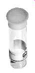
FIG. 26 A formaldehyde passive air sampler for indoor air sampling. Easy
to use, it’s designed for long-term measurement (5 to 7 days). Its detection
limit is 0.01 ppm. (SKC)
Neither of these methods is recommended for acute exposure scenarios because the sampling medium will quickly become overloaded. In acute exposure scenarios sampling with a sorbent tube attached to an air sampling pump, or a detector tube attached to a pump/bellows, is recommended. Attachment implies that the pump will be used to draw a known volume of air quickly into the media. This air will be at a concentration anticipated to provide information, but below that which would overload the media.
2. OZONE METER
The ozone meter detector uses a thin-film semiconductor sensor. A thin-film platinum heater is formed on one side of an alumina substrate. A thin-film platinum electrode is formed on the other side, and a thin-film semiconductor is formed over the platinum electrode by vapor deposition. The semiconductor film, when kept at a high temperature by the heater, will vary in resistance due to the absorption and decomposition of ozone. The change in resistance is converted to a change of voltage by the constant-current circuit.
The measuring range of the instrument is 0.01-9.5 ppm ozone in air. The readings are displayed on a liquid crystal display that reads ozone concentrations directly. The temperature range is 0-40°C, and the relative humidity (RH) range is 10-80%.
The instrument is not intrinsically safe.
• The instrument must not be exposed to water, rain, high humidity, high temperature, or extreme temperature fluctuation.
• The instrument must not be used or stored in an atmosphere containing silicon compounds, or the sensor will be poisoned.
• The instrument is not to be used for detecting gases other than ozone.
Measurements must not be performed when the presence of organic solvents, reducing gases (such as nitrogen monoxide, etc.), or smoke is suspected; readings may below.
2.1 Calibration
Calibrate the instrument before and after each use. Be sure to use a well-ventilated area; ozone levels may exceed the PEL for short periods. Calibration requires a source of ozone.
Controlled ozone concentrations are difficult to generate in the field, and this calibration is normally performed at the laboratory. Gas that is either specially desiccated or humidified must not be used for preparing calibration standards, as readings will be inaccurate.
2.2 Maintenance
The intake-filter unit-Teflon sampling tube should be clean, connected firmly, and checked before each operation. Check pump aspiration and sensitivity before each operation.
3. TOXIC GAS METERS
Toxic gas meters use an electrochemical voltametric sensor or polarographic cell to pro vide continuous analyses and electronic recording. Sample gas is drawn through the sensor and absorbed on an electrocatalytic-sensing electrode, after passing through a diffusion medium. An electrochemical reaction generates an electric current directly proportional to the gas concentration. The sample concentration is displayed directly in parts per million.
The method of analysis is not absolute; therefore, prior calibration against a known standard is required. Exhaustive tests have shown the method to be linear; thus calibration at a single concentration is sufficient.
Sensors are available for sulfur dioxide, hydrogen cyanide, hydrogen chloride, hydrazine, carbon monoxide, hydrogen sulfide, nitrogen oxides, chlorine, ethylene oxide, and formaldehyde. These sensors can be combined with O2/CGIs in one instrument ( FIG. 27).
Interference from other gases may be a problem. The sensor manufacturer's literature must be consulted when mixtures of gases are tested.
3.1 Calibration
Calibrate the direct-reading gas monitor before and after each use in accordance with the manufacturer's instructions and with the appropriate calibration gas.
• When calibrating under external pressure, the pump must be disconnected from the sensor to avoid sensor damage. If the span gas is directly fed into the instrument from a regulated pressurized cylinder, the flow rate should be set to match the normal sampling rate.
FIG. 27 BW Technologies QT-XWHM-R-Y-NA GasAlertQuattro 4-Gas Detector with Rechargeable Battery, Combustible, O2, H2S and CO, Yellow
(other toxic gas detectors)

• Due to the high reaction rate of the gas in the sensor, substantially lower flow rates result in lower readings. This high reaction rate makes rapid fall time possible-simply by shutting off the pump. Calibration from a sample bag connected to the instrument is the preferred method.
4. SEMIVOLATILE ORGANIC COMPOUNDS (SVOCs)
Semivolatiles like polycyclic biphenyls (PCBs), polynuclear aromatic hydrocarbons (PAHs), dioxins, furans, and pesticides present unique sampling challenges. The term semivolatile is used for chemicals that don’t normally volatilize into the gaseous state at room temperature (75°F; FIG. 28).
These chemicals can enter the airstream through a variety of mechanisms, the most prevalent being dispersed as adsorbed or absorbed particulate contaminants. Heating phenomena such as smoking, direct heating of semivolatiles, and chemical usage in which semivolatiles must be applied in a heated state (asphalting) may also change the semi volatiles into volatiles.
Often very high collection rates (10-30 l/min) must be used to pick up semivolatile contaminants from the airstream ( FIG. 29). Certain EPA methods and stack sampling requirements also call for the use of very high flow rates. In these instances special pumps must be used.
4.1 PAHs
PAHs have Koc values that are characteristic of chemicals that tend to readily adsorb to the soil particulate or to any other particulate present. PAHs are expected to bind strongly to soil and to not leach extensively to groundwater through volatilization.
Photolysis and hydrolysis don’t appear to be significant PAH breakdown processes in soil. However, while little volatilization will occur from the soil, leaching to groundwater is possible. PAHs released to the water will dissolve at ambient pH. The dissociated form will degrade (hours to days).
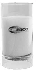
FIG. 28 High volume PUF tube for pesticides and PAHs. (SKC)
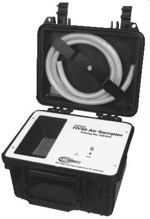
FIG. 29 Dual-diaphragm pump for indoor and outdoor collection of particulates,
PAHs, and other compounds requiring flows from 10 to 30 l/min. High-flow
pumps are used for asbestos, PAHs in indoor air, PM10 and PM2.5 in indoor
air, bioaerosol sampling, stack sampling, fenceline monitoring, and background
monitoring. (SKC-AirCheck HV30 Environmental Air Sampler)
Photolysis is expected to occur near the water surface, and biodegradation in the water column is expected. Biodegradation probably becomes significant after acclimation (may take several weeks). PAHs with four or fewer aromatic rings are degraded by microbes.
Transport of PAH biodegradation products to groundwater has been documented in some cases.
The mechanism for particulate dispersion first requires that the semivolatile chemical bind to a particulate. When that particulate is dispersed into the air, the semivolatile chemical is also dispersed. So the methods used for particulate sampling are also applicable for semivolatile sampling. The toxicological problems with the semivolatile chemical on particulate dispersion come into play as the particulate is inhaled, and off-gassing occurs in the body of the semivolatile chemical. The following decision logic is an example of the evaluation of semivolatile exposure potential, in this case PAHs, at outdoor sites:
• Usually 5 mg/m^3 is assumed to be the airborne particulate concentration necessary to have visible dust. Therefore, if during sampling activities, dust is apparent, semivolatile exposure should be of concern if the semivolatile exposure limits are less than the visible dust limits.
-PAH dust exposure PEL levels are below 5 mg/m^3 ; consequently, air monitoring would need to be conducted on any site where PAHs are expected and visible dusts are generated.
-This air monitoring should be downwind from activities judged invasive of soil layers and potentially subject to dust cloud generation.
• Monitoring for PAH levels is conducted using a personal air-sampling pump.
The exposure target limit is usually set at 0.2 mg/m^3 because that is the limit for Benzo(a)pyre. The setting of target limits for semivolatiles is usually based on the most toxic of the expected cogenitors. Cogenitors are essentially the different molecular conformations that a semivolatile chemical can take.
• Complete suspension of these contaminants within an airstream on-site is not physically probable, and misting of the sampling area should continually remove particulates from the air; therefore, high efficiency particulate air (HEPA) cartridge air-purifying respirators should be sufficient to protect samplers.
• Because PAH contamination is often associated with the presence of petroleum contamination, VOC levels should be continually monitored using a PID. If the PID records a sustained deflection of 1 ppm, workers should evacuate the exclusion zone. The presence of volatile organics revealed by sustained PID readings will require further site evaluation for PAH potential exposure.
-Further evaluation for potential exposures to PAHs will require soil sampling, with attendant air dispersion calculations and air monitoring for particulates.
-Unfortunately, we don’t have real-time instrumentation to monitor for PAHs.
PAH sampling requires that laboratory analyticals or on-site immunoassay testing must be accomplished. Therefore, until results are obtained and interpreted, on-site personnel would be required to wear HEPA-OV cartridge full face air-purifying respirators.
The on-site monitoring sequence is as follows:
• Visible dust: 2 l/min personal air-sampling pumps will be used to draw air through filter cassettes. Cassettes will be packaged and sent to the contract laboratory for analysis.
• Ongoing site work will continue with dust suppression engineering controls.
Personnel will don HEPA cartridge air-purifying respirators.
• If organic vapors are also present, HEPA-OV combination cartridges should be donned.
The above example illustrates the need for careful evaluation of the potential for expo sure during sampling. Monitoring decisions when semivolatiles are present must always be made by personnel who understand that these chemicals cannot be detected by the sense of smell or predicted by visible dust.
4.2 PCBs and Creosote
PCBs are expected in electrical transformers, fluorescent light fixture ballasts, and possibly on some building materials where oils have leaked or the transformers have exploded. Generally, all transformers and suspect containers are inspected to determine the contents of the liquids present. Site inspections include a review of transformer labels or other identifying signage. This review is conducted in the field by comparing the reviewed information against known PCB-containing placards or by conducting a phone conversation with the owner of the transformer or the manufacturer. When containers suspected of containing PCBs are found, representative samples may be collected to evaluate the content and concentrations. These samples are evaluated in the field by utilizing Rapid Assay Analysis (RAA) for PCBs or through laboratory analysis.
Building materials suspected of being contaminated with PCBs, such as concrete beneath a leaking transformer, may be sampled and analyzed following the same procedures. In the case of stained concrete, a sample would be obtained by drilling the concrete and preparing the dust for analysis.
RAA is a method utilizing amino assay techniques for field specific analysis. The amino assay field test kit is prepared in the laboratory for analyzing a specific compound, in this case PCBs or Aroclors.
4.3 Pesticides and PAHs-PUF Tubes
Both pesticides and PAHs can be collected in PUF tubes. PUF tubes are available for both high-volume and low-volume sampling ( FIG. 30). The sampling volume requirement is determined by the regulatory onus and the chemical constituency of the antic pated sample.
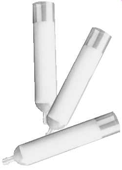
FIG. 30 Low volume PUF tubes for pesticides (for EPA Methods TO-10A and
IP-8 and ASTM D4861 and D4947) designed for sampling common pesticides, including
organochlorine, organophosphorus, pyrethrin, triazine, carbonate, and urea.
(SKC)
5. ACID GASES OR CAUSTICS
Volatile acid gases may be an inappropriate designation. Acid gases are often generated during a reaction, and the latent volatility of the acid gas is really not an issue. Thermal volatilization based on boiling point predictions and mechanical dispersion may be of less importance than the rate of the reaction generating the acid gas or caustic. However, in addition to this reaction phenomenon, acid gases such as chlorine are given off when the liquid solution is distributed around an area. Here we have a classic case of the liquid to gas interface seeking an equilibrium. If air currents sweep the generated gas concentration away from this equilibrium site, the liquid will again yield molecules to the gas phase to again achieve another equilibrium.
Acid gases and caustics with their corrosive or caustic properties can have health effects that include both acute toxicological and physical manifestations, such as watering eyes and respiratory tract irritation. Because of these effects, sampling for acid gases and caustics must begin upon approach to the area of concern.
Sampling for acid gases and caustics may use all of the techniques specified for any volatile. Some acid gases and caustics are dispersed and adsorbed to particulate; therefore, particulate sampling techniques apply.
The reaction phenomenon must always be considered during any sampling of acid gases or caustics. Any real-time instrumentation with unprotected metal sensors, lamp filaments, or sensor housings will often be rendered useless, as the acid gases or caustics interact with the metals through reduction-oxidation (redox) reactions.
5.1 Impingers
Impingers may be used to bring acid/caustic-laced particulates into solutions that are retained within the impinger's vessel. Vapors, mists, and gases may also be introduced into the impinger solution. When the reaction within the impinger vessel may cause off gassing, a filter or media barrier (see FIG. 31, 2.32, and 2.33) may be required between the air sampling pump and the impinger vessel tubing to the pump ( FIG. 34).
Midget impingers may be worn as personal sampling devices ( FIG. 35). The main concern with impingers as sampling devices, especially for personnel, is the danger of spills.
5.2 Sorbent Tubes
Sampling media must also be acid and caustic resistant. Sampling for acids and caustics is often discussed in terms of using silica gel sorbent tubes. The procedure for this sampling is the same as that for volatiles where charcoal tubes are often used. The essential problem with the silica gel tubes is that they tend to plug up! The use of dual flow tubes is some insurance that if one tube plugs up, the other might still remain effective to provide data from the sampling interval.
In instances where silica gel tubes continue to plug up, switching to larger bore silica gel tubes or altering the sampling interval (less time) may be needed. If this procedure does not work, switching to charcoal tubes may be the only other solvent tube option. These sampling routines (see FIG. 36) may be at odds with the recommended National Institute of Occupational Safety and Health (NIOSH) methods that may call for small bore silica gel tubes at low flow rates for extended periods of time. If so, decision logic must be documented, with this documentation linked to the competency of the individual who devised the sampling plan.
FIG. 31 In-line traps with replacement sorbent tubes are connected between the pump and impinger holder to protect the pump. (SKC)
5.3 Detectors
Various detector tubes are available for acid gases and caustics. Chemical-specific detectors are increasingly available as hard-wired permanent detectors based on electro chemical sensors. As with any other electrochemical sensor, recovery of the sensor after overdosing with a chemical may take time or may not be possible at all.
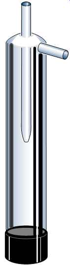
FIG. 32 Impinger trap to prevent impinger liquids from being drawn into
the sample pump. Solid sorbents may be added to the trap when volatile liquids
are used to protect the pump chambers from exposure to vapors. (SKC)
5.4 pH Litmus Paper or Meter
pH litmus papers or meters are particularly valuable on sites where acid gases and caustics may be of concern. Many sampling events require concurrent bulk sampling, and often the pH of these samples can be effectively characterized in the field.
5.4.1 Calibration
Calibrations for pH meters generally follow this regime:
• Temperature and conductance are factory calibrated.
• To recalibrate conductance in the field (if necessary):
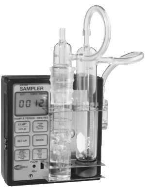
FIG. 33 Impinger and in-line trap holder mounted on sample pump. Use a
trap impinger to pre vent impinger liquids from being drawn into the sample
pump. Solid sorbents may be added to the trap to protect the pump chamber
from exposure to vapors when volatile liquids are used. (SKC)
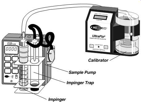
FIG. 34 Impinger/trap sampling train with flowmeter. (SKC-Universal Sampler
with Double Impinger Holder attached to UltraFlo electronic calibrator)
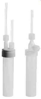
FIG. 35 Teflon PFA (fluoropolymer) impingers. These vessels are completely
inert to virtually all chemicals and perform well in both high temperature
and cryogenic applications. (SKC)
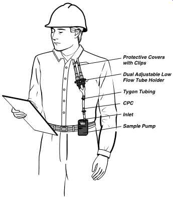
FIG. 36 Worker wearing sampling pump and two tubes side-by-side for simultaneous
tube sampling. (SKC)
-Remove the black plug revealing the adjustment potentiometer screw.
-Add standard solution to a cup, discard, and refill.
-Repeat the detection procedure until the digital display indicates the same value twice in a row.
-Adjust the potentiometer until the digital display indicates the known value of conductance.
-Increase the digital display reading by turning the adjustment potentiometer screw counterclockwise.
-Decrease the digital display reading by turning the adjustment potentiometer screw clockwise.
To standardize the pH electrode:
• Place the pH electrode in the 7.0 buffer bottle.
• Adjust the "zero'' potentiometer on the face of the tester to "7.00.''
• Place the pH electrode in the 4.0/10.0 buffer bottle (depending on range of concern at your site).
• Adjust the "slope'' potentiometer on the face of the tester to either 4.0 or 10.0.
• Repeat the "zero'' and "slope'' adjustments several times-to ensure interaction stability..