AMAZON multi-meters discounts AMAZON oscilloscope discounts
6. MERCURY ANALYZER/GOLD FILM ANALYZER
A gold-film analyzer draws a precise volume of air over a gold-film sensor. A micro processor computes the concentration of mercury in milligrams per cubic meter and displays the results on the digital meter.
This meter is selective for mercury and eliminates interference from water vapor, sulfur dioxide, aromatic hydrocarbons, and particulates. In high concentrations of mercury vapor the gold film saturates quickly and should not be used for concentrations expected to be over 1.5 mg/m^3 . Hydrogen sulfide is an interferant. Lead may also be an interferant.
6.1 Mercury Analyzer
The model discussed here to illustrate the general principles of operation in the detection of mercury vapors.

The Jerome 431 Gold Film Sensor is inherently stable and does not require frequent calibration. The interval between calibrations is recommended at every 12 months. The Jerome Mercury Analyzer is factory calibrated using National Bureau of Standards (NBS) traceable permeation tubes. These permeation tubes have been rated at an accuracy of _2%. Calibration includes stability of the calibration gas source being assured, elimination of any pressure differential in the calibration gas stream, and precise control of ambient temperature. Hence, calibration cannot be done in the field.
Bacharach 24-8440 PCA3 225 Combustion Gas Analyzer

The Jerome Mercury Analyzer, equipped with a Gold Film Sensor, has these qualities:
- • Rapid response time (_4 s)
- • LCD display-direct reading
- • Data logger and software
- • 0.003 mg/m3 Hg sensitivity
- • Accuracy _5% at 0.107 mg/Hg
6.2 Survey Procedures
• Document that the instrument is calibrated.
• Obtain and record a background reading.
• Survey with the Jerome Mercury Analyzer:
• Insert the probe in or near the area to be surveyed.
• For surface areas hold the probe 6 in. or closer to the survey point.
• For sink traps don’t put the probe in water; allow a 10-s residence time of the probe in the headspace of the trap prior to sample readout.
• Document readings in the field logbook.
• Photograph general locations and specific areas of concern.
6.3 Precautions for Area Surveys
• Include all suspected rooms, hallways, adjacent administrative space, and storage rooms, including behind and underneath cabinets, refrigerators, sinks, and equipment.
• Include all locations where mercury was used or stored.
• Include all cracks, crevices, and delaminated surface areas.
6.3.1 Calibration
Calibration should be performed by the manufacturer or a laboratory with special facilities to generate known concentrations of mercury vapor. Instruments should be returned to the manufacturer or a calibration laboratory on a regular schedule.
6.3.2 Maintenance
Mercury vapor instruments generally contain rechargeable battery packs, filter medium, pumps, and valves that require periodic maintenance. Except for routine charging of the battery pack, most periodic maintenance will be performed during scheduled calibrations.
7. PARTICULATES-SAMPLED BY FILTRATION/IMPACTION
In sampling for particulates, the particulates must be filtered out or removed from the airstream by impaction. Particulates that are suspended in the airstream come in many sizes; therefore, the first question is whether exposure standards are based on the respirable fraction or the total particulate levels.
Multiple-use calibration chambers may be used as protective environments around the various filters, cyclones, and inhalable particulate monitors. These calibration chambers effectively protect the particulate collection devices from extraneous particulate loading during calibration cycles and airstream fluctuations. Total particulates are often analyzed by gravimetric methods.
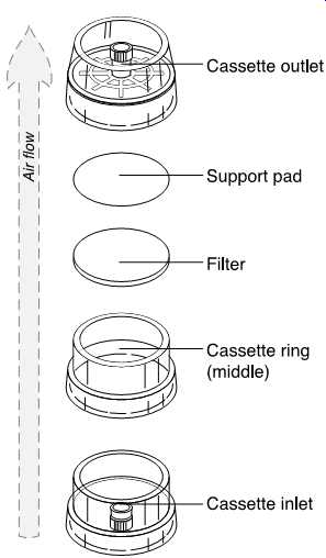
FIG. 37 Exploded view of a 37-mm filter cassette. (SKC)
8. GRAVIMETRIC FILTER WEIGHING PROCEDURE
The step-by-step procedure for weighing filters depends on the make and model of the balance. Consult the manufacturer's instruction guide for directions. In addition, follow these guidelines:
• Smoking and/or eating must not take place in the weighing area-both generate extraneous particulate matter in the airstream.
• Handle all filters with tongs or tweezers. Don’t handle filters with bare hands.
• Desiccate all filters at least 24 hours before weighing and sampling. Change desiccant before the dessicant completely changes color (i.e., before the blue desiccant turns pink). Evacuate the desiccator with a sampling or vacuum pump.
• Zero the balance prior to use.
• Calibrate the balance prior to use and after every 10 samples.
• Immediately prior to placement on the balance, pass all filters over an ionization unit to remove static charges. (After 12 months of use, return the unit to the distributor for disposal.)
• Weigh all filters at least twice.
-If there is more than a 0.005 mg difference in the two weighings, repeat the zero calibration and reweigh.
-If there is less than a 0.005 mg difference in the two weighings, average the weights for the final weight.
• Note: To avoid damage to the weighing mechanism, take care not to exert down ward pressure on the weighing pan(s).
• Record all the appropriate weighing information (in ink) in the weighing log.
• In reassembling the cassette assembly, remember to add the unweighed backup pad.
When weighing the filter after sampling, desiccate first and include any loose material from an overloaded filter and cassette.
9. TOTAL DUST AND METAL FUMES
A variety of filtration options is available to collect particulates. Sampling options are defined based on the regulatory onus and the sampling environment. Some examples of these options are as follows:
• Collect total dust on a pre-weighed, low-ash polyvinyl chloride (PVC) filter at a flow rate of about 2 l/min, depending on the rate required to prevent overloading. Weigh PVC filters before and after taking the sample.
• Collect metal fumes on a 0.8-um mixed cellulose ester filter at approximately 1.5 l/min, not to exceed 2.0 l/min.
• When the gravimetric weight needs to be determined for welding fumes, collect these fumes on a low-ash PVC filter.
Take care to avoid overloading the filter, as revealed by any loose particulate in the filter cassette housing.
Personal sampling pumps must be calibrated before and after each day of sampling, using a bubble meter method (electronic or mechanical) or the precision rotameter method (which has been calibrated against a bubble meter).
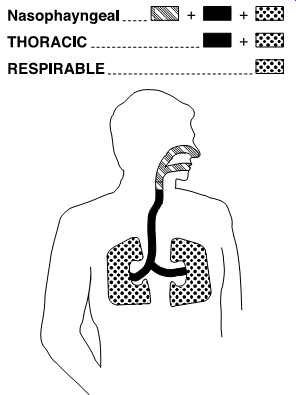
FIG. 38 Inhalable particulate dust particles have a 50% cut point of 100
ug and are hazardous when deposited anywhere in the respiratory tract. Thoracic
particulate particles have a 50% cut point of 10 ug and are hazardous when
deposited anywhere in the lung airways and gas-exchange regions. Respirable
particulate dust particles have a 50% cut point of 4 ug and are hazardous
when deposited anywhere in the gas exchange regions. (SKC)
10. RESPIRABLE DUST
Respirable dust is a component of particulates in the airstream that will deposit within the gaseous exchange areas of the lung ( FIG. 38). Respirable particles are just the right size to travel with inspired air into the alveoli of the lung. Once in the alveoli, these particles may be a simple irritant or may dissolve and, thus, become chemicals in suspension with tissue fluids. These suspended chemicals are then available to exert toxic and carcinogenic effects.
Respirable dusts that don’t go into solution pose another danger. These insoluble dusts/particulates/fibers associated with respirable dusts are easy to breathe in, proceed with ease deeply into the lung, and once in the lung may stay in the tissue bed forever.
• Inert minerals such as asbestos cause fibrosis formation within the lungs by just mechanically irritating surrounding tissue.
• Other not so inert chemicals may produce biochemical effects as the body heats up the formerly semivolatile chemicals adsorbed or absorbed on the respired particulates. PAHs off-gas in the lung and become biochemically available through this body heat phenomenon.
For total particulate sampling results the "guess'' is that 60% of the particles available in the airstream are ultimately respirable. The cut point for these particles is 50% at 4 um.
When health effects and exposure limits are based on respirable dusts,
• The 60% of total assumption must be made.
• Special instrumentation must be used to segregate out only the respirable fraction of total dust (see FIGs. 39, 40, and 41).
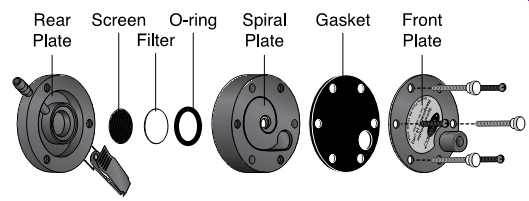
FIG. 39 Exploded view of a Spiral Sampler. (SKC)
10.1 Cyclones
Cyclones of various types (aluminum, plastic) are used to collect respirable dust fractions. Plastic cyclones are the only choice in acid-gas contaminated atmospheres ( FIG. 42, .43, and 44). Collect respirable dust using a clean cyclone equipped (see FIG. 45) with a pre-weighed low-ash PVC filter ( FIG. 46). The flow rate should be 1.5-1.9 l/min.
10.1.1 Silica Respirable Dust-Cyclone Collection
Collect silica only as a respirable dust. Aluminum cyclones are recommended to ensure that the cyclone material does not interact or become part of the sample ( FIG. 47 and 2.48). Silica at sufficient velocity may etch a plastic cyclone.
A bulk sample should also be submitted to provide a basis for comparing silica levels in stock to ultimate respirable levels of dust. All filters used must be pre- and post-weighed.
Calibration Procedures
1. Calibrate at the pressure and temperature where the sampling is to be conducted.
2. For respirable dust sampling using a cyclone, or for total dust sampling using an open-face filter cassette, set up the calibration apparatus as instructed.
3. Place the open-face filter cassette or cyclone assembly in a 1-l jar. The jar is pro vided with a special cover ( FIG. 49). If an aluminum cyclone is used, an aluminum cyclone calibration chamber can also be used in lieu of a 1-l sampling chamber ( FIG. 50).
4. Connect the tubing from the electronic bubble meter to the inlet of the jar.
5. Connect the tubing from the outlet of the cyclone holder assembly or from the filter cassette to the outlet of the jar and then to the sampling pump.
6. Calibrate the pump. Readings must be within 5% of each other.
The cyclone and filter cassette are now ready to be used. A holder makes placement of this assembly possible both for personnel and area sampling needs ( FIG. 51).
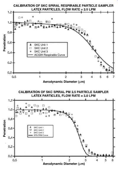
FIG. 40 Calibration curves from Aerosol Dynamics, Inc. of the SKC spiral
particle sampler PM2.5 using latex particles at 2.0 l/min. The data show
a reasonable fit to the American Conference of Governmental Industrial Hygienists
(ACGIH) respirable curve with a 4 um cut point. (SKC)
10.1.2 Cyclone Cleaning
For cyclone cleaning the following is required:
• Unscrew the grit pot from the cyclone.
• Empty the grit pot by turning it upside down and tapping it gently on a solid surface.
• Clean the cyclone thoroughly and gently after each use in warm soapy water or, preferably, wash in an ultrasonic bath.
• Rinse thoroughly in clean water, shake off excess water, and set aside to dry before reassembly.
• Never insert anything into the cyclone during cleaning.
• Inspect the cyclone parts for signs of wear or damage such as scoring, rifling, or a loose coupler.
• Replace units or parts if they appear damaged.
• Leak test the cyclone at least once a month with regular usage.
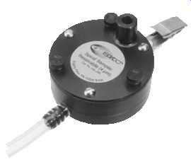
FIG. 41 Spiral Sampler for respirable dust (a model available for PM2.5).
(SKC) FIG. 42 The GS cyclone is a conductive plastic unit that holds a
filter cassette for collecting respirable dust particles. The GS cyclone
has a 50% cut point of 4.0 um at 2.75 l/min. (SKC)
11. INHALABLE DUSTS ( Above: Fig. 52 / 53)
Inhalable dusts include all of those dusts from the general airstream that normal humans can bring into their respiratory tracts. The respiratory tract includes everything from the nose to the base of the lungs ( FIG. 54).
Inhalable dusts have a 50% cut point of 100 um. Special inhalable dust samplers are used to collect only inhalable dusts; these samplers may vary according to the size of particulates collected ( FIG. 55, 2.56, and 2.57).
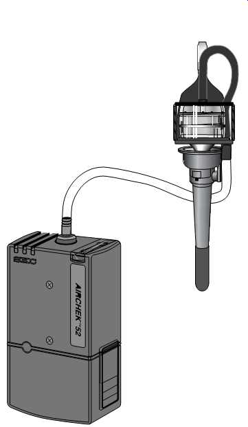
FIG. 43 GS Cyclone attached to a sampling pump. (SKC)
12. PERSONNEL ENVIRONMENTAL MONITORS (PEMs)
For particulate segregation at either the 2.5 um or 10 um size, special personnel monitors are available. These PEMs use a single-stage impaction method to select particle size.
The name is indicative of both personnel exposure concerns and the Environmental Protection Agency (EPA) particulates of concern given in the Clean Air Act requirements- thus personnel and environmental ( FIG. 58 and 2.59)!
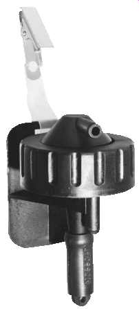
FIG. 44 The conductive plastic respirable dust cyclone is a lightweight
conductive plastic unit.
The unit is designed for a 50% cut point of 5.0 um at 1.9 l/min and 4.0 um at 2.2 l/min.
Conductive plastic construction eliminates static problems. (SKC)
13. WELDING FUMES
When sampling for welding fumes, the filter cassette must be placed inside the welding helmet to obtain an accurate measurement of the employee's exposure. If, however, the welding helmet cannot be used as a sampling environment, the personal sampling pump cassette can be attached in the breathing zone at collar level. The resulting information can be used as a screening tool: "The air outside the helmet was (not) at a level of concern; therefore, the air inside the welding helmet was (not) at a level of concern.'' Welding fume samples are normally taken using 37-mm filters and cassettes; however, if these cassettes won’t fit inside the helmet, 25-mm filters and cassettes can be used. Care must be taken not to overload the 25-mm cassette when sampling.
14. ASBESTOS
Collect asbestos on a special 0.8-um pore size, 25-mm diameter mixed cellulose ester filter with a backup pad.
• Use a fully conductive cassette with conductive extension cowl.
• Sample open face in worker's breathing zone.
• Ensure that the bottom joint (between the extension and the conical black piece) of the cassette is sealed tightly with a shrink band or electrical tape.
• Point the open face of the cassette down to minimize contamination.
• Use a flow rate of 0.5-5 l/min; 1 l/min is suggested for general sampling. Office environments allow up to 5 l/min.
• Calibrate pump before and after sampling. Calibration may be done with the cassette and cyclone replaced by the asbestos filter cassette ( FIG. 60).
• Don’t use nylon or stainless-steel adapters if in-line calibration is done.
• Sample for as long a time as possible without overloading (obscuring) the filter.
• Instruct the employee to avoid knocking the cassette and to avoid using a compressed-air source that might dislodge the sample while sampling.
• Submit 10% blanks, with a minimum in all cases of 2 blanks.
Where possible, collect and submit to the laboratory a bulk sample of the contaminant suspected to be in the air.
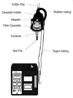
FIG. 45 A cyclone attached to air sampling pump. (SKC)
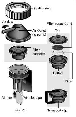
FIG. 46 Exploded
view of a respirable dust cyclone. (SKC)
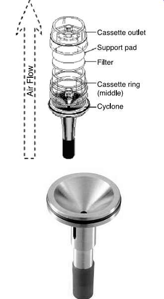
FIG. 47 Two aluminum respirable dust cyclone models can be used with a
25- or 37-mm filter loaded onto a three-piece filter cassette. The cyclone
separates the dust particles according to size. The respirable dust particles
collect on a filter for analysis, while the larger dust particles fall into
the grit pot and are discarded. (SKC)
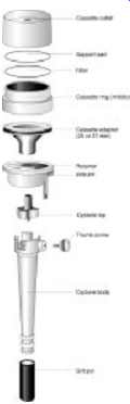
FIG. 48 Exploded view of a respirable dust cyclone cassette assembly. (SKC)
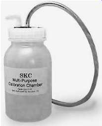
FIG. 49 A calibration chamber allows calibration when using a cyclone, PUF
tube, OVS tube, the IOM, or PEM. (SKC-Multipurpose Calibration Chamber)
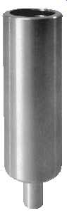
FIG. 50 Aluminum cyclone calibration chamber. (SKC)
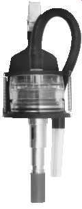
FIG. 51 Cassette holder
on aluminum cyclone with filter cassette (37 mm). (SKC)
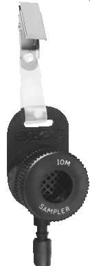
FIG. 52 Inhalable dust sampler. Simulates dust collection of the nose and
mouth. Meets NIOSH method 5700 sampling criteria for formaldehyde on dust.
(SKC-IOM Inhalable Dust Sampler)
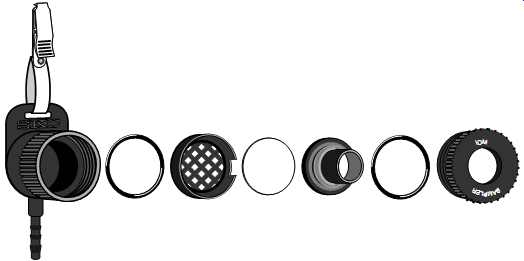
FIG. 53 Exploded view of IOM inhalable dust sampler. (SKC)
===
About Dust Exposure:
- An individual's personal dust exposure does not depend solely on dust in the outside air. People now spend less time outdoors; therefore, indoor sources of dust particles can be just as important. In the future, personal measurement of PM2.5 may become more important than ambient air dust monitoring for PM2.5 for health effects studies. The EPA plans to examine PM2.5 using personal dust sampling devices in microenvironments-inside and outside schools, homes, and workplaces.
About Particulates:
- The 4 um convention is based on respirability of all dust particles no matter the source.
- However, the PM2.5 convention separates dust particles based on likely sources. The most significant contributors to dust particles smaller than 2.5 um include mechanical processes such as rock weathering that causes windblown dust, rock crushing, building demolition, and home remodeling (plaster and wood dust). .
===
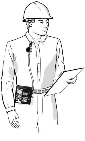
FIG. 55 Sampling train using Button inhalable dust sampler. (SKC)
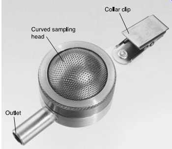
FIG. 56 A Button aerosol inhalable dust sampler is a reusable filter sampler
with a porous curved-surface sampling inlet designed to improve the collection
characteristics of inhalable dust particles (_100 um in aerodynamic diameter).
(SKC)
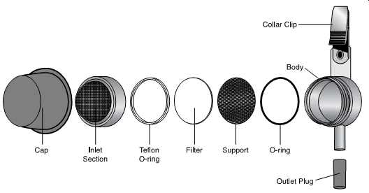
FIG. 57 Exploded view of the Button aerosol inhalable dust sampler. (SKC)
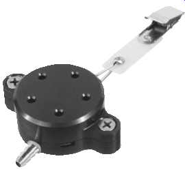
FIG. 58 The PEM is a lightweight, personal sampling device consisting of
a single-stage impactor and a final filter. Aerosol particulates are sampled
through the single-stage impactor to remove particulates above the 2.5 or
10 um cut point, depending on which sampling head is chosen. (SKC)
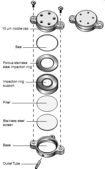
FIG. 59 Exploded view of the PEM. (SKC) --- Stainless steel screen Outlet
Tube Base Filter Impaction ring support Porous stainless steel impaction
ring Seal 10 µm nozzle cap
===
15. DIRECT-READING DUST MONITORS
15.1 Condensation Nuclei Counters (CNCs)
A CNC is a miniature, continuous-flow counter that takes particles too small to be easily detected, enlarges them to a detectable size, and counts them. Sub-micrometer particles are grown to super-micrometer alcohol droplets by first saturating the particles with alcohol vapor as they pass through a heated saturator lined with alcohol soaked felt and then condensing the alcohol on the particles in a cooled condenser. Optics focus laser light into the sensing volume.
As the droplets pass through the sensing volume, the particles scatter the light. The light is directed onto a photodiode that generates an electrical pulse from each droplet. The concentration of particles equals the number of pulses generated.
The counter counts individual airborne particles from sources such as smoke, dust, and exhaust fumes. It operates in three modes, each with a particular application. In the "count'' mode the counter measures the concentration of these airborne particles. In the "test'' (or fit test) mode measurements are taken inside and outside a respirator, and a fit factor is calculated. In the "sequential'' mode the instrument measures the concentration on either side of a filter and calculates filter penetration.
This instrument is sensitive to particles as small as 0.02 um, yet it’s insensitive to variations in size, shape, composition, and refractive index.
An example of this type of monitor is the PortaCount used to determine particulate levels during quantitative fit testing of respirators. Because of shipping regulations for flammable liquids, reagent-grade isopropyl alcohol may have to be purchased locally and used to refill the small plastic alcohol-fill tubes provided with the PortaCount. CTC also stocks and ships this alcohol. For long-term storage (over 14 days), follow the steps listed below:
• Dry the saturator felt after installing a freshly charged battery.
• Pack without adding alcohol.
• Allow the instrument to run until the LO message (low battery) or the e-e message (low particle count) appears.
• Remove the battery pack from the PortaCount.
• Install the tube plugs into the ends of the twin-tube assembly.
15.1.1 Calibration
Calibrate the counter before and after each use in accordance with the manufacturer's instructions.
FIG. 60 A sampling pump can be used in high flow (750-5000 ml/min) or low
flow (5-500 ml/min). Low flow requires an adjustable low-flow holder. (SKC-Model
224-PCXR8)
15.1.2 Maintenance
Isopropyl alcohol must be added to the unit every 5 to 6 hours of operation, per the manufacturer's instructions. Take care not to overfill the unit.
Under normal conditions a fully charged battery pack will last for about 5 hours of operation. Low-battery packs should be charged for at least 6 hours; battery packs should not be stored in a discharged condition.
15.1.3 Photodetection
Photodetectors operate on the principle of the detection of scattered electromagnetic radiation in the near infrared ( FIG. 62 and 2.63). Photodetectors can be used to monitor total and respirable particulates. The device measures the concentration of airborne particulates and aerosols, including dust, fumes, smoke, fog, mist. Certain instruments have been designed to satisfy the requirements for intrinsically safe operation in methane-air mixtures.
15.1.4 Calibration
Factory calibration is adequate.
15.1.5 Maintenance
When the photodetector is not being operated, it should be stored and sealed in its plastic bag to minimize particle contamination of the inner surfaces of the sensing chamber.
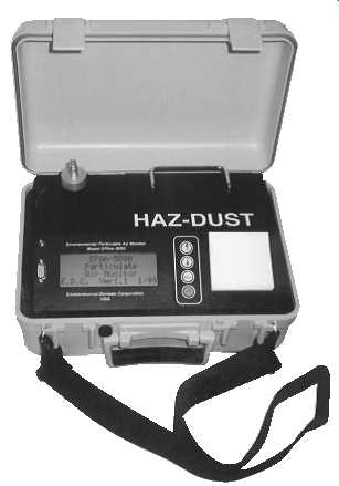
FIG. 61 Real-time dust monitoring offers immediate real-time determinations
and data recordings of airborne particle concentration in milligrams per
cubic meter. Interchangeable size-selective sampling heads allow PM10,
PM2.5, or PM1.0 monitoring. (HAZ DUST-EPAM-5000 Environmental Particulate
Air Monitor) (SKC)
After prolonged operation in or exposure to particulate-laden air, the interior walls and the two glass windows of the sensing chamber may become contaminated with particles.
Repeated updating of the zero reference following the manufacturer's procedure will correct errors resulting from such particle accumulations. However, this contamination could affect the accuracy of the measurements as a result of excessive spurious scattering and significant attenuation to radiation passing through the glass windows of the sensing chamber.
15.2 Diesel Particulate Matter (DPM)
Sampling for particulates is sometimes accomplished using surrogate sampling and analysis. In DPM sampling elemental carbon is used as the basis for evaluating DPM levels ( FIG. 64 and 65).
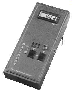
FIG. 62 Handheld dust monitors are available in handheld sizes. (SKC)
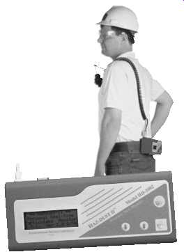
FIG. 63 This real-time dust monitor can be worn as a personal monitor.
(SKC)
FIG. 64 NIOSH Method 5040 recommends sampling for DPM by elemental analysis
of carbon as a surrogate. A cyclone is used with a 37-mm heat-treated
quartz filter and cellulose support pad that has been prepared in a carbon-free
humidity-controlled clean room. (SKC)
FIG. 65 DPM sampler assembly in cassette holder. (SKC)
16. BIOLOGICALS
The world of biological risk assessment is a new and challenging one. Until recently we did not have dynamic methods to test many areas for biological risk. Essentially we relied on shipping sampled material and swabs to laboratory sites for culturing. In some cases we were able to obtain air samples using filter cassettes or impingement onto agar plates with an Anderson air-sampling tower.
All of these methods are still used; however, a new tool is now available-an air-sampling device developed to meet the needs of clean rooms and immune-suppressed patient care medical facilities. With this new sampling device, the Reuter Centrifugal Sampler (RCS) system, we can insert an instrument the size of a handheld vacuum into locations formerly inaccessible. We can obtain a sample with a designated flow of air, e.g., 50-1000 m^3 , as a further quantification aid for samples. The samples are impinged upon air-sampling agar plates, where growth may immediately begin. Transfer to laboratory sites allows controlled further growth in biologically safe cabinets.
Contact and liquid dip agar plates are used to compare these results to airborne levels.
These plates are secured for future laboratory incubation and analysis. At no time are these or the air-sampling media plates left unattended prior to transfer to the laboratory, thereby keeping chain-of-custody intact.
Because, unlike chemicals, biologicals can and do multiply through various reproduction means, the use of personnel protective equipment (PPE) is always a requirement during sampling.
16.1 General Sampling Protocols
The following are step-by-step procedures for mold sampling:
1. Assemble materials and equipment to be used. Segregate materials and equipment to be taken inside the building or area of concern. Use impermeable plastic bags whenever possible to containerize materials and equipment to be taken into the building. Don’t use cardboard or other porous containers that cannot be readily decontaminated.
2. Mark each contact sample or strip agar blister pack with a unique sample number using a Sharpie pen. Allow the ink to air dry before overpackaging the blister pack in a baggie.
3. Using a quart or larger size Ziploc freezer bag; overpackage each contact sample or strip agar.
4. Assemble at least 10 of each type of sampling media (contact strips for the RCS) in a large overpackaged baggie. Package no more than 10 agar blister packs together for transfer to a contaminated area.
5. Assemble another bag to contain extra impermeable gloves (latex 6 mil or neoprene) and alcohol wipes. Alcohol wipes can be purchased in small manufactured packages or made up on-site using paper towels and isopropyl alcohol. The made up on-site alcohol towels are more effective for larger decontamination areas. Double bag all sources of alcohol and avoid direct alcohol contact with the agar blister packs.
6. Establish a staging area and set up a decontamination area in a biologically neutral location away from potential biological amplification sites.
7. Don PPE in the following order:
• Don first hooded Tyvek.
• Don boots.
• Don first and second layer of gloves (double gloving is optional in some situations).
• Duct tape boot/glove openings at ankles/wrists (optional in some situations).
• Don respirator.
• Don second hooded Tyvek (optional in some situations).
8. Begin the sampling routine. Sample outside and in all assumed uncontaminated or amplified areas first; then sample into progressively more contaminated areas.
Use the same protocols for all sampling events, including the same pressure and motion when using contact plates and the same walking routines or static placement when using the RCS.
16.2 Contact and Grab Sampling
Contact and specimen grab-sampling routines are as follows:
1. Open sample overbag at first location to be sampled.
2. Sample mold by applying the contact plate to the area with some pressure, by swabbing, or by obtaining a small sample of contaminated building (or other) material.
3. Place mold-contaminated item into the sample bag or swab vial.
4. Seal the overbag.
5. Decontaminate gloves if contaminated by direct contact or if pathogenic fungi are suspected.
6. Place used decon pad into small waste bag.
7. Decontaminate spatula or any other tools used.
8. Place decon pad (if used) into small waste bag. Decon pads can be baggies or small pieces of precut plastic.
9. Decontaminate outside of sealed sample bag if contaminated by direct contact or if pathogenic fungi are suspected.
10. Place used decon pad into small waste bag.
11. Repeat steps 1-10 for additional sampling locations.
16.3 Reuter Central Fugal System (RCS)
Both high-volume and low-volume RCS units are available (see FIG. 66 and 67).
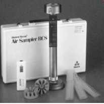
FIG. 66 Biological air sampling instrument. (Biotest Diagnostic Corp. Air
Sampler RCS)
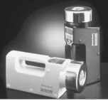
FIG. 67 RCS centrifugal air sampler. (Biotest Diagnostic Corp.)
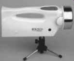
FIG. 68
Tripod and remote can be used to sample for biological contamination
in ventilation systems. (Biotest Diagnostic Corp.)
We also recommend:
Gowe® Portable Air Sampler, Air Flow: 100l/min, Cute
BioScience 18198 SAS Super 100 Air Sampler for Monitoring Air for Bacteria, Fungi and Viruses, 315mm L x 105mm W x 108mm H


The RCS units can be mounted on stands if necessary ( FIG. 68). RCS sampling routines are as follows:
1. Open sample over bag at first location to be sampled.
2. Insert RCS agar strip into the RCS impeller assembly. Don’t directly touch the agar medium at any time. In the event that the agar is touched, discard that agar strip.
3. Sample mold by running the RCS for the approved time duration.
4. Remove the RCS agar strip from the RCS impeller assembly. Don’t directly touch the agar medium at any time. In the event that the agar is touched, discard that agar strip.
5. Place the RCS agar strip into the original sample overbag.
6. Seal the overbag.
7. Decontaminate gloves if contaminated by direct contact or if pathogenic fungi are suspected.
8. Place used decon pad into small waste bag.
9. Decontaminate outside of sealed sample bag if contaminated by direct contact or if pathogenic fungi are suspected.
10. Place used decon pad into small waste bag.
11. Repeat steps 1-10 for additional sampling locations.
The RCS in some circumstances may need to be decontaminated between sampling events. In the field the impeller assembly can be cleaned with isopropyl alcohol and thoroughly air-dried in a biologically neutral location. If further decontamination is required, the RCS will need to be decontaminated at the issuing laboratory.
In some circumstances pathogenic sleeves must be used with the RCS. Don’t take the RCS carrying case or battery charger into a contaminated environment.
At the conclusion of a sampling event, at a minimum, wipe down the RCS exterior with alcohol wipes. (Contact a CIH for additional decontamination requirements.) Use equipment decon pads to decontaminate temporary lighting and any other large equipment used. Note: Lights are turned off prior to decontaminating. The last set of lights may be decontaminated using handheld flashlights for illumination.
16.4 Exit Requirements
When exiting the area...
• Seal all used interior decon pads in small waste bag.
• Exit area.
• Decontaminate outer Tyvek and respirator with decon wipes.
• Remove outer Tyvek.
• Place used Tyvek into large waste bag.
• Decontaminate inner Tyvek, gloves, and boots.
• Place used decon pads into waste bag.
• Remove duct tape from wrists/ankles.
• Remove boots, gloves, and Tyvek.
• Place used boots, gloves, and Tyvek into large waste bag.
• Seal large waste bag.
• Decontaminate respirator again prior to removal. Place used decon pads into (new) small waste bag.
• Remove respirator.
• Use decon pads to decontaminate hands.
• Place all used decon pads into small waste bag.
• Bag all disposable equipment for disposal in an approved manner (contact CIH for project specific advice as to disposal).
• Bag all non-disposable equipment for further decontamination off-site (contact CIH for project specific advice as to disposal).
16.5 Static Placement Impingement
Less mobile sampling devices are also available. These include the use of filter cassettes to collect all spores-viable and nonviable. The Anderson sampling device has various impaction trays installed to segregate spores on the basis of size.
16.6 Bioaerosols
When bioaerosols must be collected, extremely high flow rates may be required. The rule in general is that sonic flow requires a 0.5 atm pressure drop ( FIG. 69). As with all pumps, the greater the pressure drop, the faster the intake of air toward that pressure void area.
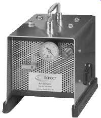
FIG. 69 A non-compensating vacuum pump is capable of maintaining the 0.5
atm pressure drop required for sonic-flow applications. (SKC-Vac-U-Go Sampler)
17. RADIATION MONITORS AND METERS
17.1 Light Meter
The light meter is a portable unit designed to measure visible, UV, and near-UV light in the workplace.
The light meter is capable of reading any optical unit of energy or power level if the appropriate detector has been calibrated with the meter. The spectral range of the instrument is limited only by the choice of detector.
Steady-state measurements can be made from a steady-state source using the "normal operation'' mode. Average measurements can be read from a flickering or modulated light source with the meter set in the "fast function'' position. Flash measurements can be measured using the "integrate'' function.
Exposure of the photomultiplier to bright illumination when the power is applied can damage the sensitive cathode or conduct excessive current.
17.1.1 Calibration
No field calibration is available. These instruments are generally very stable and require only periodic calibration at a laboratory.
17.1.2 Maintenance
Little maintenance is required unless the unit is subjected to extreme conditions of corrosion or temperature. Clean the optical unit with lens paper.
Detector heads should be recalibrated annually by the manufacturer only. All calibrations are National Institute of Standards and Technology (NIST) traceable.
The Ni-Cad batteries can be recharged. Avoid overcharging, which will reduce battery life.
18. IONIZING RADIATION
Because ionizing radiation cannot be detected by the human senses, detection and quantification must be accomplished by specifically designed instruments. All such methods of measurement employ a substance that responds to radiation in a measurable way and a system or apparatus to measure the extent of the response. Most radiation detectors operate by one of two methods: ionization or scintillation.
The selection of instruments is based on the type and energy range of the radiation expected on-site. Survey instruments will be chosen for their sensitivity to the type of radiation present in the area to be surveyed. The method of relating the instrument reading to milliroentgens per hour will be included.
Some instruments can measure multiple types of radiation and require methods for determining which type of radiation is being measured. For example, neutron detectors for neutron dose can be quantified using boron trifluoride (BF3) detectors.
The ionizing radiation survey meter is useful for measuring radon decay products from air samples collected on filters.
• The barometric pressure should be noted for ionizing radiation chambers.
• Wipe samples collected on a filter can also be counted with this detector, and general area sampling can be done.
• The survey meter with the scintillation detector can be used to measure the presence of radon-decay products in a dust sample.
18.1 Ionization Detectors
Most ionization detectors consist of a gas-filled chamber with a voltage applied; a central wire becomes the anode, and the chamber wall becomes the cathode. Any ion pairs produced by radiation interacting with the chamber move to the electrodes, where they are collected to form an electronic pulse that can be measured and quantified. Depending on the voltage applied to the chamber, the detector may be considered a gas proportional detector, a Geiger-Muller (GM) detector, or an ion chamber.
18.1.1 Gas Proportional Detectors
Thin-window gas proportional detectors may be used to detect alpha and beta radiation. Distinction between alpha and beta is achieved by adjusting the voltage of the detector.
18.1.2 Ion Chamber
An ionization chamber is a gas-filled chamber containing an anode and a cathode. As radiation passes through the gas, it ionizes some of the gas molecules. These ion pairs are attracted to the anode and cathode and create an electrical pulse. The pulses are counted, integrated, and displayed on the meter face in roentgens per hour. Ion chambers provide a nearly linear response to gamma and X-ray radiation above a few kiloelectron volts in energy and at radiation levels above 0.1 mR/h. For this reason an ion chamber is the only instrument for quantifying radiation exposures. Ion chambers may be used to quantify the beta, gamma, or X-ray dose at a location.
Sodium iodide (NaI) scintillation detectors, used on survey meters, provide better counting efficiency for gamma and X-rays, but have a more limited range of energies, depending on the size of the crystal and the density of the window. NaI detectors may be used to detect the presence of gamma radiation, but only if the energy level of the radiation is known, and the correct size crystal is used.
18.1.3 GM Detector
Because of its versatility and dependability, the GM detector is the most widely used portable survey instrument. AGM detector with a thin window can detect alpha, beta, and gamma radiation. The GM is particularly sensitive to medium-to-high energy beta particles (e.g., as from 32 P), X-rays, and gamma rays. The GM detector is fairly insensitive to low-energy X-rays or gamma rays, such as those emitted from 125 I, and to low-energy beta particles, such as those emitted by 35 S and 14 C; it cannot detect the weak betas from 3 H.
Unlike the ion chamber the GM detector does not actually "measure'' exposure rate. It instead "detects'' the number of particles interacting in its sensitive volume per unit time.
The readout of the GM is in counts per minute (cpm), although it can be calibrated to approximate milliroentgens per hour for certain situations. With these advantages and limitations a GM detector on a rugged survey meter is the instrument of choice for initial entry and survey of field radiation sources and radioactive contamination.
GM detectors are calibrated to one energy level of the electromagnetic spectrum- usually 662 keV, the gamma energy from the decay of 137 Cs, and are read out in milliroentgens per hour. GM detector efficiency for radiation at other energies is not linear.
GM detectors can be used to detect the presence of radiation, but only as a rough estimate of the dose rate. Beta shields will compensate for blocking betas and reading gamma or X-ray radiation. Subtraction of the gamma or X-ray radiation readings will yield an approximation of the beta contribution. Beta contribution should be read in counts per minute.
18.2 Scintillation Detectors
Scintillation detectors are based upon the use of various phosphors (or scintillators) that emit light in proportion to the quantity and energy of the radiation they absorb. The light flashes are converted to photoelectrons that are multiplied in a series of dynodes (i.e., a photomultiplier) to produce a large electrical pulse. Because the light output and result ant electrical pulse from a scintillator is proportionate to the amount of energy deposited by the radiation, scintillators are useful in identifying the amount of specific radionuclides present (i.e., scintillation spectrometry).
Solid scintillation detectors are particularly useful in identifying and quantifying gamma-emitting radionuclides. NaI scintillation detectors, used on survey meters, provide better counting efficiency for gamma and X-rays, but have a more limited range of energies, depending on the size of the crystal and the density of the window. NaI detectors may be used to detect the presence of gamma radiation, but only if the energy level of the radiation is known, and the correct size crystal is used.
The common gamma counter employs a large (e.g., 2__ 2_ or 3__ 3_) NaI crystal within a lead-shielded well. The sample vial is lowered directly into a hollow chamber within the crystal for counting. Such systems are extremely sensitive, but don’t have the resolution of more recently developed semiconductor counting systems. Portable scintillation detectors are also widely used for conducting various types of radiation surveys. Of particular use to researchers working with radioiodine is the NaI thin crystal detector capable of detecting the emissions from 125 I with efficiencies nearing 20% (a GM detector is less than 1% efficient for 125 I).
The most common means of quantifying the presence of beta-emitting radionuclides is through the use of liquid scintillation counting. In these systems the sample and phosphor are combined in a solvent within the counting vial. The vial is then lowered into a well between two photomultiplier tubes for counting. Liquid scintillation counting has been an essential tool of research involving radiotracers such as 3 H, 14 C, 35 S, and 45 Ca.
One problem that occurs with liquid scintillation counting is determining the efficiency of the system. The low-energy photons produced by the beta particles interacting with the scintillation cocktail are easily shielded from the photomultiplier tubes due to optical and chemical quenching. To account for this artifact, a quench curve must be computed using a set of increasingly quenched standards and a method of determining a quench indicating parameter for each standard. The quench curve is a graph for a certain nuclide of each standard's quench-indicating parameter (QIP) vs. the efficiency of the counter. The efficiency for an unknown sample is then determined by measuring its QIP, with the graph determining the counter's efficiency for that sample. Then use that quantity and the counts per minute of the sample to determine the disintegration rate (dpm) of the sample.
Fortunately, most modern counters compute and store quench curves from a single counting of a standard set, use an external standard to determine the QIP, and automatically output sample counts in disintegrations per minute.
The other common problem with liquid scintillation counting is chemiluminescence.
Certain chemicals when mixed with some scintillation cocktails will cause the cocktail to emit photons, resulting in a higher count rate than actually exists from the radionuclide itself. Rule of thumb: Let scintillation vials wait for a few hours after mixing the cocktail and the material to be assayed to allow for the initial chemiluminescence to be exhausted.
18.3 Counting Efficiency
The purpose of radiation counting systems is to determine sample activity (microcuries or disintegrations per minute). However, because of numerous factors related to both the counting system and the specific radionuclide(s) in the sample, the radiation detector can never see 100% of the disintegrations occurring in the sample. The counts per minute displayed by the counter must therefore be distinguished from the disintegration rate of the sample.
The ratio of the count rate to the disintegration rate expressed as a percent is the efficiency of the counting system.
cpm/dpm _ 100% _ efficiency (1)
Because every counting system will register a certain number of counts from environmental radiation and electronic noise in the counter (i.e., background), a more correct formula is as follows:
[(Sample cpm - bkg cpm)/Sample dpm] _ 100% _ efficiency (2)
Example 1
A 1-ml sample of a solution of 125 I is counted in a gamma scintillation spectrometer with a window of 15 keV to 75 keV. A 0.1 _Ci 125 I standard and a background sample are counted along with the solution for 1-min each. The results are as follows:
0.1 _Ci _ 2,220,000 dpm _ 2.22 _ 106 dpm/_Ci Background (bkg) _ 35 cpm Standard _ 110,658 cpm Sample _ 3,246,770 cpm Efficiency of the counter:
_ [(Sample cpm - bkg cpm)/Sample dpm] _ 100% _ efficiency
_ [(110,658 - 35)/(0.1 _ 2.22 _ 106 dpm/_Ci)] _ 100% _ 0.4983
_ 49.8% efficiency of the counter Activity of the sample:
_ (Sample cpm - Background)/(efficiency _ dpm per _Ci)
_ (3,246,770 - 35)/[0.4983 _ (2.22 _ 106 dpm/_Ci)]
_ 2.935 _Ci/ml of sample Example 2
A sample containing a 14 C-labeled amino acid is counted in a liquid scintillation counter. The sample count rate is 1200 cpm, and the background is 30 cpm. If the counter is 85% efficient for 14 C, what is the activity within the sample? Sample cpm - bkg cpm/Sample dpm _ efficiency
_ (1200 _ 30)/85 _ 1376 1376 dpm _ 2.22 _ 106 dpm/_Ci
_ 6.2 _ 10_ 4
_Ci
18.4 Monitoring for Radioactive Contamination
Monitoring instruments must be chosen for their sensitivity to the type of radiation to be monitored. A method of relating the instrument reading to microcuries must be included.
Monitoring must be performed slowly and at distances of 1 to 2 mm from the surface to detect low-intensity radiations. The monitoring results must be documented and must include the following:
• Identification of the instrument used to monitor
• Name of the person performing the monitoring
• Location, date, and time of monitoring
• Results of the monitoring
• Comments on any factors that might influence the readings
18.5 Daily Use Checks
Each survey instrument must have an appropriate check source attached or assigned to the instrument. The check source for the instrument must be surveyed immediately after calibration, and the reading must be written on the calibration sticker on the instrument.
Before each use of the instrument, the check source must be monitored, and the reading compared to the reading noted on the calibration sticker. Any meter not measuring within _10% of the reading on the calibration sticker must be tagged as requiring maintenance and must not be used until maintenance and recalibration have been performed.
Surveys must be performed slowly; the instrument needs time to integrate and display the measurement.
Survey results must be documented and must include the following:
• Identification of the instrument used to perform the survey
• Name of the person performing the survey
• Location, date, and time of the survey
• Results of the survey
• Comments on any factors that might influence the survey
18.6 Survey Instrument Calibration
Survey instruments must be calibrated periodically using procedures outlined in the instrument manual, within the following guidelines:
• All sources used to calibrate instruments must be traceable to NIST.
• The survey meter and the probe must be calibrated as a unit. If probes are changed, the unit must be recalibrated prior to use.
• Instruments must be calibrated at least annually.
• Instruments must be calibrated after every maintenance or repair operation.
The date of calibration, the date the next calibration is due, and the initials of the person performing the calibration must be written on a calibration sticker attached to the instrument.
19. NONIONIZING RADIATION
Electromagnetic fields (EMFs) produced by computer terminals, cellular phones, electric blankets, and power lines can be measured. Microwave radiation, whether used for communication, electron wave propulsion, or food warming, can also be measured.
EMFs are generated any time charged particles move through a medium. Two fields are actually produced, one electric and one magnetic. Both are always found together.
The earth itself is the largest source for a magnetic field, and lightning generates one of the strongest electric fields. Electricity transmitted through a wire produces an EMF proportional in size to the current flow and the voltage drop.
Another issue associated with EMFs is the corona phenomenon, where air around a high voltage power line is ionized and interferes with TV and radio reception. This ionization can also generate ozone that may be a health concern.
The electromagnetic spectrum is very broad and consists of low-frequency, low-energy waves, such as those generated by power lines, through high-energy, high-frequency cos mic rays.
• The wavelength of most interest is around 60 Hz. This frequency is the one most commonly used in the United States for electrical power transmission and falls into a range known as extremely low frequency EMF. The extremely low frequency EMF range is from 5 Hz to 2000 Hz. These waves are extremely long and can be easily shielded or attenuated.
• Cellular phones broadcast radio signals at around 850 MHz. These radio signals are equivalent to most television transmission frequencies. Cellular phones operate at a much higher frequency than most household sources of EMF.
• Ionizing radiation, such as X-rays, have a frequency of around 2.5 _ 1015 Hz.
Ionizing radiation, in very high doses, is known to lead to an increase in cancer incidence.
19.1 Guidance
No legally enforceable exposure standards are in place for any nonionizing radiation.
The non-Ionizing Radiation Committee of the International Radiation Protection Association recommends the following standards for 60 Hz EMF:
Magnetic field strength:
• 5 Gs-occupational exposure
• 1 Gs-public exposure Electric field strength:
• 10,000 V/m^3 -occupational exposure
• 5,000 V/m^3 -public exposure
Surveys of ten commonly used video display terminals gave readings in the following ranges:
• Magnetic field strength of 0.0006 to 0.0077 Gs
• Electric field strength of 1.6 to 15 V/m^3
19.2 Broadband Field Strength Meters
Broadband field strength meters are available for measuring electromagnetic radiation in the frequency range from 0.5 MHz to 6000 MHz. Each meter comes with probes for measuring either magnetic or electric field strength, batteries, headset, and carrying case.
This unit is designed for laboratory and field use to measure magnetic and electric fields near radio frequency (RF) induction heaters, RF heat sealers, radio and TV antennas, or any other RF sources.
• All units have automatic zeroing. There is no need to place the unit in a zero-field condition to zero it.
• All units have a peak memory-hold circuit that retains the highest reading in memory.
• All units operate with either electric (E) or magnetic (H) field probes based on diode-dipole antenna design. Total field strength is measured at the meter regardless of the field orientation or probe-receiving angle. The diode-dipole antenna design of the probe is much more resistant to burnout from overload than the thermocouple design of probes used with other meters.
19.2.1 Calibration
No field calibration is available. Periodic calibration by a laboratory is essential.
19.2.2 Maintenance
No field maintenance is required other than battery-pack charging or replacement.