AMAZON multi-meters discounts AMAZON oscilloscope discounts
This section contains theoretical and real-world discussions about the intricacies of calibration.
It gives special emphasis to situations where the knowledge of calibration techniques is a prerequisite for sampling adequacy.
Calibration is the means used to provide evidence that instrumentation is working accurately and that results are reliable and repeatable within the tolerance levels prescribed for these instruments. The calibration of real-time instruments is very specific, and manufacturer's instructions must be followed. Increasingly, instrumentation is calibrated using electronic circuitry, with empirical tests against standards in accordance with the manufacturer's requirements at prescribed intervals.
Collection efficiency must also be taken into account when calibration curves are developed. As filters, cartridges, or sorbent tubes load, air intake and calibrated airflow volumes across the media can be expected to change (FIG. 1).
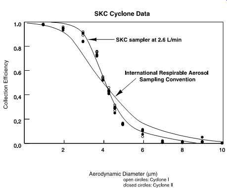
FIG. 1 SKC cyclone sampler at 2.6 l/min collection efficiency vs. aerodynamic
diameter.
1. CALIBRATION REQUIREMENTS
Instrument calibration records must be reviewed periodically by the users to assess accuracy of documentation and to evaluate instrument performance. Assessment is based on the instrument operating instructions and knowledge of the user.
• Users will check minimum calibration frequency requirements for the instrument and calibrate according to the applicable operating instruction manual.
• Calibrating the instrument at the worksite under actual field conditions is an important requirement.
• Air-sampling instrument readings for calibration will be corrected for tempera ture and barometric pressure.
Record calibration and challenge results as follows in the field log book and include the following information:
• Instrument identification
• Date (if not on page in logbook)
• Precalibration readings as found or as set
• Readings after calibration and span settings, if applicable
• Calibration gas (challenge) used and lot number
• Signature of person performing calibration
1.1 Calibration Assurance
The user will transport the instrument to the field in its carrying case or by other means that will adequately protect the instrument. All devices to be used in the field sampling train must be in-line during calibration ( FIG. 2).
Relevant information such as the type of instrument to be used, frequency of monitoring, and specific warning and action levels are found in the site safety and health plan or Activity Hazard Analysis (AHA) written for the specific job site. The user must follow these requirements:
• Users are expected to follow the specific manufacturer's operating instruction manual for the instrument being used. The user takes a field copy of the operating instruction manual into the field with the instrument.
• Prior to entering a contaminated zone, the user will take appropriate precautions to prevent contamination of the instrument, e.g., using plastic bags or filters.
• The instrument is used in accordance with the applicable operations and maintenance (O&M) manual and site safety and health plan.
• Data are recorded in the field logbook.
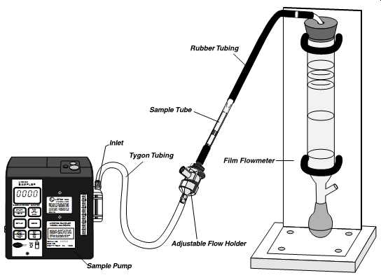
FIG. 2 A primary standard flowmeter connected to a sampling train. (SKC)
1.2 Decontamination
Decontamination of instruments is necessary to remove contaminants present at a site.
The user is expected to take the proper steps to assure the instrument is clean prior to leaving a contaminated zone. A radiation release sticker may be required depending on the circumstances of radioactive contamination on-site.
Decontamination procedures will vary depending on the individual contaminants and circumstances involved. Steps may be as simple as wiping down the instrument probe with soap and water or as involved as disassembly and thoroughly cleaning with decontamination agents.
Decontaminate the instrument in accordance with the site safety and health plan decontamination procedures or instructions provided by air monitoring professionals.
1.3 Maintenance
Users should not attempt field repairs other than preventive maintenance, cleaning, adjustments, or decontamination. Major repairs must be done by a qualified instrument technician or the factory. Refer to the O & M manual for maintenance instructions. Flow-rate holders also require frequent maintenance to assure consistent operation ( FIG. 3).
• Battery charging will be done in accordance with the manufacturer's O&M manual to prevent overcharging or possible damage to the equipment.
• Manufacturer's preventive maintenance procedures and major repairs by the factory or instrument technician will be recorded in the field log guide or calibration logs for that instrument.
• After field maintenance, instrument calibration is invalidated, and recalibration is necessary prior to use.
The terms primary and secondary calibration devices are used in field calibration.
Primary calibration means that a physical phenomenon whose progression is dictated by the laws of physics is measured for quantification. Such a physical phenomenon is the time required for a bubble to move up a glass tube or the time required for a gas to evaluate a chamber.
Secondary calibration involves the use of equipment previously calibrated against a primary standard. Such equipment is often the proper choice because primary standards often cannot be readily transported and relied upon under field conditions.
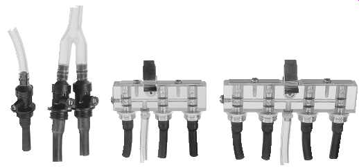
FIG. 3 Single, double, triple, and quadruple adjustable low flow holders.
(SKC)
2. MANUAL BURET BUBBLE METER TECHNIQUE (PRIMARY CALIBRATION)
When a sampling train requires an unusual combination of sampling media (e.g., glass fiber filter preceding impinger), the same media/devices should be in-line during calibration. Calibrate personal sampling pumps before and after each day of sampling ( FIG. 4).
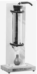
FIG. 4 This portable standard flowmeter can be used in the office or
laboratory, and in the field. (SKC)
2.1 Bubble Meter Method
For the Bubble Meter Method use the following procedures:
1. Allow the pump to run 5 min prior to voltage check and calibration.
2. Assemble the polystyrene cassette filter holder using the appropriate filter for the sampling method.
3. If a cassette adapter is used, care should be taken to prevent contact with the backup pad.
4. Note: When calibrating with a bubble meter, the use of cassette adapters can cause moderate to severe pressure drop in the sampling train, which will affect the calibration result. If adapters are used for sampling, then they should be used during calibration.
5. Connect the collection device, tubing, pump, and calibration apparatus.
6. A visual inspection should be made of all Tygon tubing connections.
7. Wet the inside of a 1-l burette with a soap solution.
8. Turn on the pump and adjust the pump rotameter to the appropriate flow-rate setting.
9. Momentarily submerge the opening of the burette in order to capture a film of soap.
10. Draw two or three bubbles up the burette so the bubbles will complete their run.
11. Visually capture a single bubble and time the bubble from 0 to 1000 ml for high flow pumps or 0 to 100 ml for low-flow pumps.
12. The timing accuracy must be within +/-1 s of the time corresponding to the desired flow rate.
13. If the time is not within the range of accuracy, adjust the flow rate and repeat steps 9 and 10 until the correct flow rate is achieved. Perform steps 9 and 10 at least twice in any event.
14. While the pump is still running, mark the pump or record (on the calibration record form) the position of the center of the float in the pump rotameter as a reference.
Repeat the procedures described above for all pumps to be used for sampling. The same cassette and filter may be used for all calibrations involving the same sampling method.
Calibration of multiple tubes, whether in series or in parallel, is sometimes required.
Any flow adjustment mechanisms and critical orifices must also be installed in the sampling train during these calibrations. When flexible tubing is used, it must be consistently used in all applications during sampling events (FIG. 5).
3. ELECTRONIC FLOW CALIBRATORS
Electronic flow calibrators are high-accuracy, electronic bubble flowerets that provide instantaneous airflow readings and a cumulative averaging of multiple samples.
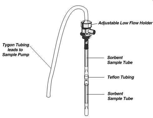
FIG. 5 Two sorbent sampling tubes in series with a single adjustable
low-flow holder. (SKC)
• These calibrators measure the flow rate of gases and present the results as volume per unit of time.
• These calibrators may be used to calibrate all air-sampling pumps.
• The timer is capable of detecting a soap film at 80-us intervals.
• This speed allows under steady flow conditions an accuracy of +/-0.5% of any display reading.
• Repeatability is +/-0.5% of any display.
• The range with different cells is from 1 ml/min to 30 l/min.
• Battery power will last 8 h with continuous use. Charge for 16 h. These meters can be operated from A/C chargers.
When a sampling train requires an unusual combination of sampling media (e.g., glass fiber filter preceding impinger), the same media and devices should be in-line during calibration ( FIG. 6).
3.1 Cleaning Before Use
Before using an Electronic Flow Calibrator:
• Remove the flow cell and gently flush it with tap water. The acrylic flow cell can be easily scratched.
• Wipe with cloth only.
• Protect center tube, where sensors detect soap film, from dirt and scratches.
• Never clean with acetone. Use only soap and warm water.
FIG. 6 The electronic flow calibrator using soap bubbles is easy to use and suitable for field use. (SKC)
When cleaning a flow cell prior to storage, allow it to air-dry. If stubborn residue persists, it’s possible to remove the bottom plate. Squirt a few drops of soap into the slot between base and flow cell to ease residue removal.
3.2 Leak Testing
The system should be leak checked at 6-in. H2O by connecting a manometer to the out let boss and evacuate the inlet to 6 in. H2O. No leakage should be observed.
3.3 Verification of Calibration
The calibrator is factory calibrated using a standard traceable to the NIST, formerly called the NBS.
• Attempts to verify the calibrator against a glass 1-l burette should be conducted at 1000 ml/min for maximum accuracy.
• The calibrator is linear throughout the entire range.
3.4 Shipping and Handling
When transporting, especially by air, one side of the seal tube that connects the inlet and outlet boss must be removed for equalizing internal pressure within the calibrator. Don’t transport the unit with soap solution or storage tubing in place.
3.5 Precautions and Warnings
Avoid the use of chemical solvents on the flow cell, the calibrator case, and the face plate. Generally, soap and water will remove any dirt.
• Never pressurize the flow cell at any time with more than 25-in. water pressure.
• Don’t charge batteries longer than 16 h.
• Don’t leave A/C adapter plugged into calibrator when not in use to avoid damage to the battery supply.
• Close-fitting covers help to reduce evaporation of soap in the flow cell when it’s not in use.
• Don’t store flow cell for 1 week or longer without removing soap.
• Clean the flow cell and store dry.
Calibrator soap is a precisely concentrated and sterilized solution formulated to pro vide a clean, frictionless soap film bubble over the wide, dynamic range of the calibrator.
The sterile feature of the soap is important to prevent residue buildup in the flow cell center tube, which could cause inaccurate readings. The use of any other soap is not recommended.
4. ELECTRONIC BUBBLE METER METHOD
Various electronic meters are available that mimic the performance of the bubble burette. Most use shortened bubble tubes and calculate this shortened tube length as though the bubble burette was the standard size. The protocol for using these meters is as follows:
• Connect the collection device, tubing, pump, and calibration apparatus.
• Visually inspect all Tygon® tubing connections.
• Wet the inside of the electronic flow cell with the soap solution by pushing on the button several times.
• Turn on the pump and adjust the pump rotameter, if available, to the appropriate flow rate.
• Press the button on the electronic bubble meter. Visually capture a single bubble and electronically time the bubble. The accompanying printer will automatically record the calibration reading in liters per minute.
• Repeat these steps until two readings are within 5%. If necessary, adjust the pump while it’s still running.
• Repeat the procedures described above for all sampling pumps. The same cassette and filter may be used for calibrations involving the same sampling method.
For sorbent tube sampling, however, the sorbent tube to be used must be used during the calibration.
Note: When calibrating with a bubble meter, cassette adapters can cause moderate to severe pressure drop at high-flow rates in the sampling train and affect the calibration result.
• If adapters are used for sampling, they should also be used for calibrating.
• Caution: Nylon adapters can restrict airflow due to plugging.
• Stainless-steel adapters are preferred.
5. DRY-FLOW CALIBRATION
With the advent of computer chip and microcircuitry technology, dry-flow calibration of instruments is now possible. Dry-flow calibrators measure the flow across near friction less composite pistons ( FIG. 7). For some pumps, an adapter must be used between the pump and the dry-flow calibration instrument ( FIG. 8).
In addition to measuring flow rates, the calibration devices can also record time, date, employee names, pump ID, sample ID number, and other programmed information ( FIG. 9).
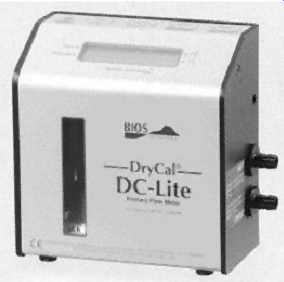
FIG. 7 An electronic flow calibrator is available that does not use soap;
instead it uses a graphite/carbon-composite piston that rises in the chamber
like the bubble. (Bios International Corp.) (other electronic flow calibrators)
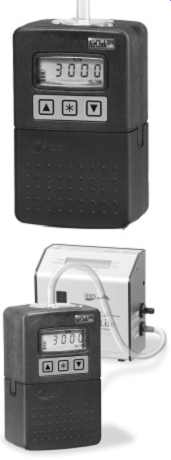
FIG. 8 An electronic adapter is available to automatically calibrate
an air sampling pump. (SKC-AirCheck® 2000 air sampling pump, CalCheck®
Communicator with DC-Lite calibrator). (Bios International Corp.)
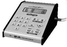
FIG. 9 The electronic standardization and communication module provides
time/date stamping; employee, pump, and sample ID numbers; volumetric flow
rate readings; and readings at user-defined time intervals for flow stability
testing. (Bios International Corp.)
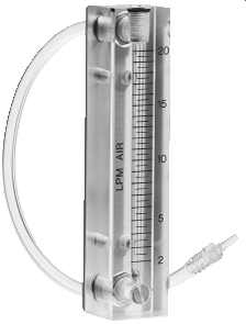
FIG. 10 Secondary standard rotameters are used in the field to calibrate
air-sampling pumps. (other rotameters)
Rotameters are calibrated to a primary standard. Flow rates must be corrected for standard temperature and pressure. (SKC)
6. PRECISION ROTAMETER METHOD (SECONDARY)
The precision rotameter is a secondary calibration device. If used in place of a primary device such as a bubble meter, take care that any error introduced is minimal and noted (FIG. 10).
6.1 Replacing the Bubble Meter with a Precision Rotameter
The precision rotameter may be used for calibrating the personal sampling pump in lieu of a bubble meter, provided it is:
• Calibrated regularly, at least monthly, with an electronic bubble meter or a bubble meter.
• Disassembled, cleaned as necessary, and recalibrated. (It should be used with care to avoid dirt and dust contamination, which may affect the flow.)
• Not used at substantially different temperature and/or pressure levels than when the rotameter was calibrated against the primary source.
• Used in such a way that the pressure drop across the rotameters is minimized.
If altitude or temperature at the sampling site is substantially different from that at the calibration site, it’s necessary to calibrate the precision rotameter at the sampling site.
7. SPAN GAS
Span gas of known concentration can be used to calibrate detectors. An example is the use of span gas in a PID.
A known concentration of a gas that readily ionizes in the PID energy lamp's electron voltage is drawn into the ionization chamber. Essentially this gas spans the distance between the anode and cathode sides of the ionization chamber. The detector must there fore detect this span and send an appropriate electrical signal to the readout device.
The electrical output to the detector readout for the PID is then adjusted. The reason for this adjustment or calibration is that with a known concentration of a gas that will ionize at a known voltage, the PID should detect and read out the same as the concentration listed on the compressed gas bottle.
Isobutylene has an IP of 9.8 eV and is the usual calibration gas of choice for PIDs
Historically, benzene was used (same IP of 9.8 eV); however, that use was discontinued due to benzene's carcinogenic and toxic effect potential. Remember that after the ionization cycle, the gases reform and are exhausted from the PID reaction chamber. The other expo sure route occurred when the calibration gas was attached to the sampling train.
8. BUMP TESTING
Bump testing is used to check sensor operation. This sensor check is not a substitute for the calibration of sensors. However, bump testing can:
• Provide an indication of sensor reliability under field conditions.
• Indicate when calibration is required.
• Test all sensors simultaneously.
Bump testing involves the use of a bump test gas cylinder filled with known concentrations of various gaseous challenge agents. These gases each provide a known percent age or parts per million component. The gas cylinder is attached to an instrument's inlet portal or diffusion grid, and the instrument's detector readouts are compared to the bump gas known concentration ( FIG. 11).
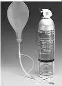
FIG. 11 Bump testing needs to be performed regularly to ensure that real-time
air monitoring instrumentation is functioning properly. (MSA)