AMAZON multi-meters discounts AMAZON oscilloscope discounts
Overview
Enclosures, which include control panels and cabinets, house items of instrumentation and controls as well as their peripherals such as wiring, terminal blocks, power supplies, and the like. Enclosures are typically assembled in a panel assembly shop by professionals who should know in detail what the owner's requirements are. It is therefore important that the plant pre pare a specification that covers the design, construction, assembly, testing, and shipping of the enclosure.
AMAZON multi-meters discounts AMAZON oscilloscope discounts
A typical specification should address the following topics: general requirements, documentation, fabrication, protection and rating, nameplates, electrical considerations, pneumatics, temperature and humidity control, inspection and testing, certification, and shipping. This Section will address these topics.
There are many type of control panels (see FIG. 1).
• Vertical panels are simple in design and cost less than the others; they could be wall or floor mounted.
• Slant-top section panels use their top segment typically to mount annunciators or semi graphic displays.
• Consoles are used to facilitate operator access to push buttons and indicator lights.
• Desk front panels are commonly used to provide an operator with a "look-over" capability.
• Breakfront panels provide good access and improve aesthetics. They tend to be custom built and therefore cost more than regular panels.
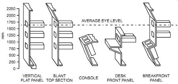
FIG. 1 Panel front shapes.
General Requirements
One of the first rules in building control panels is to ensure that all electrical components com ply with the requirements of the current edition of the electrical code in effect at the site and that they are approved by and bear the approval label of the testing organization (e.g., UL, FM, CSA, etc.). In most cases, the panel assembly shop furnishes the panel completely fabricated and finished, with all components mounted, piped, wired, and tested. This work should be done in accordance with the requirements the owner identified in a specification. These requirements will vary with project needs, but typically a specification states that:
• all instruments and equipment that the specification does not indicate the owner will sup ply to the panel assembly shop shall be supplied by the panel assembly shop. This ensures that no devices, however minor, are forgotten.
• the work of assembling the enclosure should be carried out by certified and trained trades men, who should have adequate supervision and the equipment necessary to complete the work. The panel assembly shop may also be required to produce evidence of tradesmen's certification and training to ensure that only qualified personnel assemble the panel.
• the panel assembly shop is responsible for correctly installing and assembling all items or equipment and for carefully reading and rigidly adhering to the manufacturer's instructions. Any damage caused by failure to observe the manufacturer's instructions must be the responsibility of the panel assembly shop.
• uniformity of manufacture is maintained for any particular item throughout the panel. This facilitates the inventorying of spare parts and reduces the need for training of on-site maintenance personnel.
• all instruments are installed and connected so they can be maintained and removed for servicing without having to break fittings, cut wires, or pull hot wires. This includes providing the necessary unions and tubing connections for all instruments (to facilitate their removal for maintenance).
• for enclosures that are located outdoors, rain shields are commonly required even if the enclosures are of weatherproof construction. This is because rainwater could drip inside the panel while the doors are open during construction or maintenance, and destroy the electronic equipment.
Additional information is available from ISA's recommended practice ISA-RP60.3-1985, Human Engineering for Control Centers.
Documentation
The owner (or his appointed representative, such as an engineering firm) should supply the panel assembly shop with the documentation to completely and correctly fabricate and assemble the enclosures. Such documentation typically includes instrument index, loop diagrams, electrical control schematics, instrument specifications, nameplate drawing (where applicable), certified vendor drawings (where applicable), and front-of-panel general layout.
The front-of-panel general layout normally shows the physical size of the control panel and the approximate positions of front-of-panel instruments, lights, switches, push buttons, and displays. This drawing may also give the approximate locations of cable and tube entries and electric/pneumatic supplies, while leaving the determination of the exact dimensions to the panel manufacturer.
Before construction begins, the panel manufacturer is expected to furnish detailed drawings to the owner for approval. These drawings typically include steel fabrication drawings (used only for custom panels); detailed front-of-panel layout; detailed back-of-panel layout; wiring diagram and terminal layout; and tubing, air header, and bulkhead layouts. Additional information is available from ISA's recommended practice ISA-RP60.4-1990, Documentation for Control Centers.
Fabrication
Standard off-the-shelf enclosures are used for most applications. Custom-built panels involve high cost, long delivery times, and relatively low quality control during fabrication. Given the diversity of available standard off-the-shelf enclosures and their modularity, custom panels have become a rarely supplied item.
When selecting standard enclosures, the users should keep in mind that they must comply with the codes and regulations in effect at the site, the area classification, the environmental requirements, and the application/plant requirements. In some applications, the content of an enclosure will need to be viewed regularly. To avoid having to frequently open and close the enclosure door, acrylic door panels are installed that enable the content to be viewed. Keep in mind, however, that non-metallic enclosures do not provide protection to noise-sensitive electronic equipment.
Sometimes for security reasons, locked enclosures are specified. Designers must give this careful consideration, since locking an enclosure may create problems in emergencies when immediate access is required. Examples include extinguishing a fire that is starting inside the enclosure or even performing regular maintenance when the key cannot be found. To avoid these situations, personnel may just leave the key on the panel-defeating its purpose.
It is a good practice to allow spare panel space (say 25 to 30%), thus allowing for the installation of future equipment without having to buy and install new panels. Unused panel areas should be kept free of wiring and terminals to facilitate the mounting and wiring of future equipment.
When designing a panel, the layout of incoming and outgoing wiring is closely related to the location of input/output modules. Therefore, input/output module placement determines the routing of wires.
Protection and Rating
Enclosure protection and rating is usually described according to one of two systems: the NEMA system (for National Electrical Manufacturers Association, the system common in North America) and the IEC/CENELEC Ingress Protection (IP) code (CENELEC is the European Committee for Electrotechnical Standardization). The NEMA system defines the characteristics of an enclosure according to certain tests and to their locations, indoor or outdoor (see tables 12-1 and 12-2).
The IEC/CENELEC approach commonly states the degree of protection in terms of a code "IPxy," where x relates to the ingress of solid foreign objects and y for the ingress of liquids (see tables 12-3 and 12-4). There is no direct correlation between the two systems. However, TABLE 5 shows a conversion from NEMA type numbers to IP codes.
Nameplates
Nameplates are required to identify panel equipment. For all panel instruments, the panel fabricator should supply and mount an engraved three-ply laminated plastic nameplate (for example, white-on-black core) that indicates the tag number as shown on the drawings. The characters must be big enough so the tag number can be read clearly from a reasonable distance. Nameplates for panel devices can be attached with adhesives only in air conditioned room environments, whereas in all other areas they are mechanically attached with rivets or screws. Additional information on nameplates is available from ISA's recommended practice ISA-RP60.6-1984, Nameplates, Labels, and Tags for Control Centers.
TABLE 1 Enclosures for indoor locations.
TABLE 2 Enclosures for outdoor locations.
TABLE 3 Degree of protection against contact and entrance of solid foreign bodies.
TABLE 4 Degree of protection against ingress of liquids.
TABLE 5 Conversion of NEMA type numbers to IEC IP codes (Do not use this table to convert from IP codes into NEMA type numbers).
Electrical
In a typical enclosure arrangement, the wiring is routed so that all wires connected to the panel go to individual terminals and the wire number is identified with a permanent marker reflecting the number shown on the drawings. Spare terminals should always be added. For example, a minimum of 25 percent or 10 spare terminal points, whichever is greater, should be provided on each strip. In addition, all terminals must be suitably protected so the accidental touching of live parts is unlikely.
Good engineering practice requires that no more than two wires go to one terminal point and that no wire splicing be permitted in cable ducts or anywhere in the panel except on identified terminal blocks. Some applications require weatherproof wire splices (instead of terminal blocks) to ensure no short circuits will occur if wire terminations get wet. In some cases, plants standardize on colors and wire gages. This allows maintenance personnel to identify the function of a wire just by looking at it.
Where a common 24-V DC power supply is needed to power many instrument loops, the panel manufacturer may be required to supply and install a dual power supply system. Such a system should be protected by diodes in case one of the two should fail. In addition, each power sup ply unit should have sufficient power for all the loops in the panel and still have at least 25 per cent spare capacity. For each of the two power supplies it is helpful to have an output contact to alarm in case of failure.
It is a good practice for each instrument loop to have its own terminal-mounted power-supply disconnect switch, especially for startup and maintenance/troubleshooting activities. This enables each loop to be serviced individually without affecting other loops. This disconnect typically includes its own overload protection device rated for the low-power instrument loop (e.g., 0.5A fuse).
120-V AC wiring is typically run in cable ducts that are separate from low-voltage wiring. The panel assembly shop should furnish and install multiple circuit power distribution panels with circuit breakers. To avoid electrical noise problems, the plant must run thermocouple (and other very low-voltage signals), 24-V DC, and 120-V AC wiring in three separate cable ducts.
To facilitate the work of maintenance personnel, at least two tool receptacles (with ground fault protection) and overhead lighting should be provided for every eight feet (2.5 m) of panel length. Fluorescent lighting is a source of electromagnetic interference. If such lighting must be used then some precautions should be implemented to protect the panel-mounted electronic equipment. These precautions include enclosing the switch in a metal enclosure, shielding the cable between the lamp and the switch, and installing a shielding grid over the lamp. The power for panel-mounted instruments and back-of-panel instruments is sometimes provided by a three-prong grounded plug and flexible cord running to conveniently located receptacles, while all other wiring is hardwired to terminals.
To ensure that the safety of equipment used in hazardous areas is not jeopardized, the plant should install only certified equipment in hazardous areas and should strictly follow the code requirements. Where purging is required, it is normally done with clean, dry, oil-free instrument air. This purging should conform to the pressure-sensing and interlocking requirements of the electrical code in effect at the site.
Additional information on implementing electrical equipment in hazardous areas is available from ISA-12.
Pneumatics
Pneumatic tubing is not often implemented in the typical enclosure since most modern equipment is electronic. In applications where pneumatic tubing is required and in the absence of plant standards, the plant may use ISA-RP60.9-1981, Piping Guide for Control Centers.
It is a good practice to have all of the external connections terminate at a bulkhead plate. Also, each bulkhead termination should be permanently identified, and the tubing should be identified by permanent markers according to the instrument loop diagrams. This approach minimizes the chance of errors during maintenance or whenever the tubes are disconnected. To allow for future expansions and unforeseen modifications, the panel should have a minimum number of spare bulkhead connections, complete with their bulkhead union fittings, on the bulkhead plate (for example, 20 percent or six spare bulkhead connections, whichever is greater).
All tubing should be installed in a neat and orderly manner, free from distortions, and run with adequate support. Similarly, all tubing should be arranged so instruments and accessories can be easily removed and maintained. As with the wiring, the tubing may be color coded to facilitate identification of functions.
For the air supply system inside the panel, a 2-in. (50 mm) instrument air supply header is typically required. This header is supplied with ¼-in. takeoff points equipped with shutoff valves for each instrument and a ¼-in. drain valve at its lowest point. Again, the panel should have a number of spare takeoffs with shutoff valves (for example, 20 percent). In addition, the panel assembly shop should also supply and install a duplex air filter regulator, complete with an input and an output pressure gage. Each filter regulator should have a capacity at least 25 per cent greater than that required by the instruments installed in the panel. The panel's air supply system should also have a pressure-relief valve that is capable of handling the combined maxi mum capacity of the two filter regulators. It should be located on the downstream side of the filter regulators.
After the enclosure is assembled, the panel assembly shop should ensure that all installed lines are clean, both internally and externally, and that all joints are free from leaks.
Temperature and Humidity Control
If temperature and humidity conditions are a concern, an HVAC or heating unit may have to be mounted in the enclosure. Instead of an expensive HVAC unit, plants sometimes purge with instrument air and maintain a slightly positive air pressure (about 0.1 inches of water column) to cool the inside of a panel.
Inspection and Testing
The owner's representative should be able to visit the panel assembly shop at any time to check progress and/or inspect the enclosure and its internal components. When all assembly work is completed, the panel assembly shop is expected to thoroughly check the enclosure mechanically and functionally before the owner's representative arrives. To avoid damaging sensitive electronic equipment, the shop should not use high-voltage insulation testing equipment. The assembly shop will, as a minimum, perform the following checks after the enclosure is completed:
1. The physical appearance and mechanical construction of the enclosure, inside and outside
2. All nameplates for correct location, spelling, wording, and letter size
3. Any signs of physical damage or negligence
4. All electrical power circuits needed for correct operation
5. All air supply lines required for correct operation
6. Leaks in pneumatic lines
7. All electrical and pneumatic circuits needed for correct functional operation, loop by loop
8. All alarm circuits required for correct operation
Certification
In situations where the enclosure must be certified, the assembly shop should obtain the necessary documents from the appropriate authorities for all inspections. The cost of all such inspections should be born by the panel assembly shop. Any deficiencies noted by such inspections should be corrected by the panel assembly shop at no cost to the owner. After all approvals have been obtained, the panel assembly shop should affix to the panel any labels (e.g., union labels) covering electrical and pipe fitting as required in the enclosure specification.
Shipping
To avoid damage during shipping to the plant, the panel assembly shop removes all tray-mounted and plug-in instruments from their manufacturer's boxes, reboxes them, and ships them separately to the plant in tagged boxes. The enclosure, suitably protected, should then be shipped by air-ride truck. Additional information is available from ISA's recommended practice, ISA-RP60.11-1991, Crating, Shipping, and Handling for Control Centers.