AMAZON multi-meters discounts AMAZON oscilloscope discounts
Overview
Control valves are a continuously varying orifice in a fluid flow line that changes the value of a process variable by changing the rate of flow. The typical control valve consists of three main components: the body, the trim (usually consisting of a plug and seat), and the actuator.
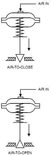
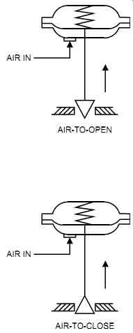
Fig. 1
Valve failure mode with different valve/actuator setups.
AMAZON multi-meters discounts AMAZON oscilloscope discounts
In most applications, a control valve is the final element in a control loop. It provides the power needed to translate the controller's output to the process, either in a two-position (on off) or proportional (throttling) control mode. Of the three basic components of a typical control loop (sensor, controller, and valve), the valve is subject to the harshest conditions and is the least understood. To complicate matters, the valve is also the most expensive and most likely to be selected incorrectly.
A successful control valve installation requires both knowledge and experience. First, personnel must gather the process information and then select the appropriate valve. Additional information on control valves is available from the ISA-75 series of standards.
Selecting the right valves involves the following factors:
• Process requirements: The type of fluid passing through the valve, the inlet pressure and differential pressure (dp) across the valve, the maximum and minimum flows, the flowing temperature, and the degree of shutoff.
• Correct sizing of the valve: The valve must be able to handle its maximum design flow (say, at 75% fully open). However, the designer must avoid oversizing or under-sizing since they degrade the valve's operation. Typically, a properly sized valve should not operate below the 10 percent or above the 90 percent travel position.
• Suitable flow characteristics: The valve's flow characteristics must match the process requirements (i.e., linear, equal percentage, or quick-opening)-refer to section on "Trim" in this Section.
• Fail-safe mode (on air and/or signal failure): An air-to-open valve is a fail-closed valve (FC); a spring closes the valve on air failure, and air must open it. An air-to-close valve is a fail-open valve (FO); a spring opens the valve on air failure, and air must close it (see FIG. 1).
• Proper choice of valve body type (i.e., globe, ball, etc.) and accessories: For example, for applications that are toxic or environmentally hazardous, bellows seals may be required.
• Correct installation: always refer to the vendor's recommendations.
Shutoff
Control valves that are well designed provide stop valve tightness. However, a slight leakage will normally occur through the valve trim, particularly where a valve has been in service for a while. The amount of allowable valve leakage can be defined at the design stage. In accordance with ANSI/FCI 70-2, valve leakage is classified according to six classes, which are summarized as follows:
Class I: no test required
Class II: 0.5 percent of rated valve capacity, tested with clean air or water at the maximum operating differential pressure or 45 to 60 psi (300 to 400 Kpa), whichever is less
Class III: 0.1 percent of rated valve capacity, tested with clean air or water at the maximum operating differential pressure or 45 to 60 psi (300 to 400 Kpa), whichever is less
Class IV: 0.01 percent of rated valve capacity, tested with clean air or water at the maximum operating differential pressure or 45 to 60 psi (300 to 400 Kpa), whichever is less
Class V: 0.0005 mL/min of water per inch of port diameter per psi differential, tested with clean water at the maximum operating differential pressure or 100 psi (700 Kpa), whichever is less
Class VI: bubble-tight, tested with clean air or nitrogen gas at the maximum operating differential pressure or 50 psi (350 Kpa), whichever is less. For example:
1 in. port diam.; leak rate = 0.15 mL/min or 1 bubble/min 2 in. port diam.; leak rate = 0.45 mL/min or 3 bubble/min 4 in. port diam.; leak rate = 1.7 mL/min or 11 bubble/min 8 in. port diam.; leak rate = 6.75 mL/min or 45 bubble/min
If tight shutoff is required, the plant may provide a tight shutoff isolation valve in series with the throttling valve. Otherwise, the soft seat on a throttling valve with tight shutoff may need frequent replacement.
Noise
Valve noise is caused by the mechanical vibration of valve components and by fluid noise.
Fluid noise can, in turn, be generated by hydrodynamic and aerodynamic noise.
Mechanical noise is typically caused by the lateral movement of the valve plug in relation to the guide surfaces. It is generally not predictable and should not occur with a good valve design. If it is does occur, the plant can generally eliminate it by replacing the valve plug. Better plug guidance may also do the job.
Hydrodynamic noise is caused by cavitation or flashing. Aerodynamic noise is created by the deceleration of the fluid, or expansion immediately downstream of the vena contracta. Valve noise can be calculated, and if it is determined that it will occur, it can be reduced by one (or a combination) of the following methods:
• Specially designed valves with multiple paths: to drop the pressure in gradual steps
• Valves in series: to divide the pressure drop over two valves
• A valve with a downstream multiple orifice plate in series: to increase the valve's down stream pressure
• Silencers: to reduce noise
• Cover piping with insulation: to reduce noise traveling through the pipes
Flashing and Cavitation
Flashing and cavitation are detrimental to valves, drastically shortening their useful life. Cavitation progresses through two steps: (1) flashing, where the liquid becomes vapor, and (2) the vapor collapses back into liquid (an implosion). Cavitation sounds like a hissing noise on the downstream side of the valve when it starts. When fully developed, it sounds like gravel passing through the valve.
No cavitation or flashing occurs if the fluid's vapor pressure is lower than the pressure at the vena contracta (Pv1 in FIG. 2). This is because the fluid started as a liquid and, through the vena contracta, remained a liquid. However, if the fluid's vapor pressure (Pv3 in FIG. 2) is higher than the discharge pressure P2, flashing will occur since the liquid turns into vapor and stays as such at pressure P2. If P2 is higher than the fluid's vapor pressure (Pv2 in FIG. 2), then cavitation will occur. This is because the liquid becomes vapor as its pressure drops below Pv2 and then returns back to liquid as it crosses Pv2 to become P2.
Mechanical damage is the main result of cavitation. Cavitation gives the trim assembly the appearance of eroded holes or a porous surface. Flashing can produce serious valve erosion, resulting in a fine, sanded surface with a smooth, polished finish. Where cavitation is expected, plants should select special trims or reduced pressure drop across the valve to reduce the effects of wear and noise.
Pressure Drop
All valves, because of their resistive nature, drop most of the pressure across their trim (see FIG. 2). The lowest pressure is located at a point just downstream of the trim, a point known as the vena contracta. The amount of pressure drop depends on the valve's geometry, and thus varies among valve types and even between two valves of the same type from different manufacturers. As the pressure drop across a valve increases, so does the flow. However, a point will be reached (the chocked-flow condition) where increasing the pressure drop, will not increase flow.
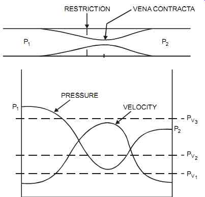
FIG. 2 Pressure and velocity profiles caused by a restriction in a line.
When users must decide how much of the total pressure drop should be taken across the valve, some rules of thumb are helpful. The pressure drop across the valve, as a percentage of the dynamic losses of the system, could be around 10 to 20 percent (5% is an absolute minimum and only if the flow variations are minimal) or 5 to 10 psi (35 to 70 kPa), whichever is greater.
It should be noted that if less than 30 to 40 percent of the total pressure drop is across the valve, the equal percentage will give better control than the linear.
Installation
Installing valves correctly is essential, and the user must always refer to the vendor's recommendations to ensure satisfactory performance. During pipeline pressure testing, the plant should keep the valves fully open to avoid high differential pressures across the valve. Pipe work on either side of the control valve should be supported, and eccentric reducers should be used where condensables or sludge could be trapped upstream of the valve (i.e., allow drain age). It is good practice to allow five pipe diameters upstream (and downstream) of the valve to minimize disturbances and achieve the stated flow characteristics. However, if space is restricted, allow one pipe diameter upstream (and downstream) as a minimum.
Usually, all actuators are mounted with their stems vertical above the valve body. If the valve will operate in a dusty environment, the plant should install a rubber boot around the stem to protect its polished finish. When removing valves from toxic, acid, or alkaline service, always flush and clean the valve to protect maintenance personnel and the environment.
The Cv
Valve sizing is based on the Cv, which is the number of U.S. gal/min of water at 60°F (15.5°C) when there is a 1 psi (6.9 kPa) differential pressure (dp) drop across the valve. A valve with a Cv of 20 means that when fully open, the valve will pass 20 U.S. gal/min of water with a 1 psi (6.9 kPa) dp.
Valve Cv is determined through test results. For the same type of valve of the same size, different vendors may have different Cv values as a result of different valve designs and geometry.
For liquids Note: At extremely low Reynolds numbers (typically for small valves), the flow becomes laminar, and Q becomes proportional to dp rather than the square root of dp.
Generally, valves are selected so they pass a flow that is larger than the expected maximum design flow when they are wide open and at design pressure drop. However, the valve should not be oversized. Control valves, despite having sufficient capacity (Cv) to handle the flow, are typically one size smaller than the inlet and outlet piping or have reduced trim sizes. If for some reason (e.g., to handle future increases in flow) a plant's valve is specified to line size, the plant may need to reduce the trim to provide good control. The reduced trim can then be replaced in the future with a full-size trim to handle the larger flows.
Valve Bodies
Valve bodies can be classified into two types based on their motion: linear and rotary. Linear valves comprise globe (including three-way and angle), gate, diaphragm, and pinch types.
Rotary valves include ball, butterfly, and plug types.
Line connections for control valves are available in a variety of configurations. They may be flanged, wafer-style, threaded, or welded. Flanged connections are used in most applications and also for toxic applications where threaded valves or valves clamped between flanges are unacceptable. Valves with wafer-style connections are clamped between the adjoining line flanges. This design provides a decrease in valve weight and space requirements and is simpler to install. Wafer-style connections are common with butterfly valves. Threaded connections are generally used for small sizes, typically under 1 to 2 in. (25 to 50 mm). Welded connections are generally used for highly toxic, very high-pressure flammable materials and some other specific applications. They are supplied as butt-weld (the valve ends are beveled to match the pipe bevel) or socket-weld (the valve ends have an inside diameter slightly larger then the pipe's outside diameter).
Rules of Thumb
Valve selection is application dependent. However, the following rules of thumb may help the user select a type of valve. The user's experience and the vendor's recommendations should also be carefully evaluated.
1. For most modulating control applications, and considering the effects of cost, controllability, and maintenance, the following guidelines apply:
• Globe valves are used for up to 3 in. (80 mm) lines.
• Globe, characterized ball, and eccentric rotary-plug valves are used for 3- to 6-in. (80 to 150 mm) lines.
• Characterized ball, eccentric rotary-plug, and butterfly valves are used for 6- to 12-in. (150 to 300 mm) lines.
• Butterfly valves are used for larger than 12-in. (300 mm) lines.
Cv QU.S. gal min / () specific gravity dp psi ()
-- - × =
2. Ball, eccentric, butterfly, and diaphragm valves are used for most on-off applications.
Cooling Fins (Radiating Bonnet) and Bonnet Extensions
Cooling fins are used to protect the packing and actuator from extreme temperatures. They are typically required when fluid temperatures above 400°F (200°C) are handled. Bonnet extensions are generally required on temperature applications below -20°F (-30°C).
Bellows Seals and Packing
Bellows seals are used to prevent leakage when the packing fails or where standard packing may let noxious fluids leak into the surroundings. They are fragile and expensive and are generally limited to 150 psig (1 MPag) at 570°F (300 °C). In some cases, 500 psig (3.5 MPag) can be obtained with thicker bellows.
Sometimes sealing can also be obtained with double packing since this is less expensive than bellows sealing. Extra packing can also be used with bellows as a safety feature if the bellows fails. The space between the packings may have to be vented to a tank to capture any emissions. In certain cases, the space between the packings may have to be pressurized.
Valve packing isolates the process fluid from the outside world. The valve packing material under the operating conditions must remain elastic and easily deformable, must be chemically inert and as frictionless as possible, and must be easily accessible for maintenance.
Comparison Table
TABLE 1 summarizes the main types of control valves with respect to a set of common parameters. This comparison table can be used as a guide to selecting control valves. The information presented indicates typical values; vendors may have equipment that may exceed the limits shown.
Globe
Globe valves are the most versatile of all valves. They are ideal for high-pressure drop applications, are available with either single- or double-seated construction, and may have pressure balanced trim. The single-seated valve (see FIG. 3) is typically used on all 1-in. (25 mm) and smaller valves and is usually top guided. The double-seated valve (see FIG. 4) requires fewer actuator forces and is top and bottom guided. However, it is more expensive; more difficult to service, maintain, and adjust; and does not provide tight shutoff. The double seated valve is not commonly used. Three-way valves (see FIG. 5) are an extension of the typical double-seated globe valve.
TABLE 1 Control valve comparison. [coming soon]
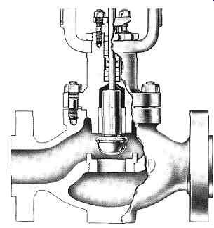
FIG. 3 Single-seated globe valve.
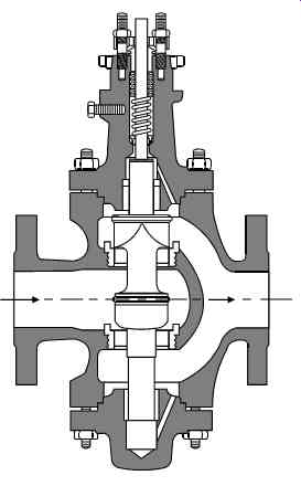
FIG. 4 Double-seated globe valve.
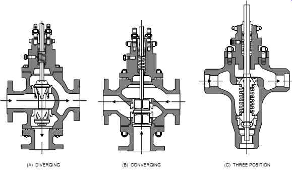
FIG. 5 Three-way globe valves.
Another type of globe valve is the angle valve (see FIG. 6). This is considered a single seated valve, and its streamlined interior, with its self-draining construction, tends to prevent solid buildup inside the body. These valves are also used for erosive fluids and in situations where the piping arrangement restricts the use of globe valves. Angle valves are typically offered in 1- to 6-in. (25 to 150 mm) sizes, but they are not available in jacketed construction.
They are generally installed with the flow coming in on the side and exiting at the bottom. This configuration minimizes body erosion but will create a flow-to-close valve (i.e., it could slam shut) and a high-pressure recovery condition (i.e., it is prone to noise and cavitation).
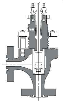
FIG. 6 Angle valve.
Globe valves are also available in a split-body configuration (see FIG. 7). This design is easily maintained and slightly less expensive than the regular globe valve. It is also relatively free of pockets in which sediments can settle. However, in the split-body configuration pipe, stresses are transmitted to the body bolting, which may cause misalignment and valve leakage.
Another type of globe valve that is very popular is the cage-guided balanced trim valve (see FIG. 8). This design uses the cage as a plug guide. The plug is grooved along its sides, which equalizes the pressure in the valve body. The cage-guided balanced trim valve provides a balanced valve plug, valve plug guiding, and excellent shutoff capabilities.
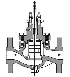
FIG. 8 Cage-guided balanced trim globe valve.
Globe valves are excellent as modulating control valves. They provide a wide selection of body and trim material, a broad choice of flow characteristics and shutoff requirements (note that double-seated valves do not shut off tightly), and excellent cavitation and noise control with special trims. However, globe valves are the most expensive type of valve and should not be used on slurries or in dirty/solid-bearing fluids.
Globe valves can be either "flow to open" or "flow to close." The flow-to-open design pro vides better stability, maximum capacity, and quieter, smoother operation. The flow-to-close design tends to slam shut near the seat position, and strong actuators are required to balance this effect. However, this consequence is minimal if the valve is under 1 in. (25 mm).
The typical globe valve can be steam-jacketed to provide heat that prevents the flowing fluid from freezing. Bellows are available where they are required. Globe valve designs of the bar stock type are good for small flows and high-pressure drops.
Diaphragm (Saunders)
Diaphragm valves, also known as Saunders valves, are operated by forcing a flexible diaphragm against a bridge or weir to stop the flow. The weir-type design (see FIG. 9a) lasts longer than the straight-through type, but has less flow capacity. The straight-through valve, sometimes called a "pinch valve" (see FIG. 9b), is best suited for slurries but has a lower differential-pressure rating than the weir design.
Diaphragm valves are excellent for sanitary and slurry service as well as for liquids that contain solids or dirt. They are made of a packless construction (because fluid contacts only the liner) and are available as tight shutoff. Diaphragm valves are low-cost devices and their maintenance is simple. However, they have poor flow characteristics and are inadequate as modulating control valves. In addition, the diaphragm materials available are limited, and due to their application and construction, diaphragm valves tend to be a high-maintenance item.
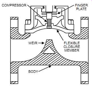
FIG. 9a Weir-type diaphragm valve.
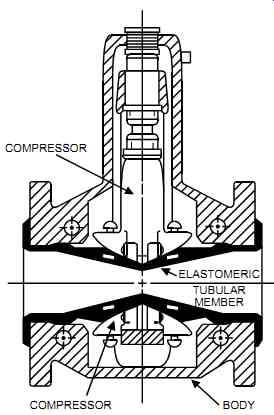
FIG. 9b Straight-through diaphragm valve.
Ball
The ball valve is a rotary-action valve (see FIG. 10). Some manufacturers mount the ball eccentrically so the face of the ball lifts when it rotates off the seat, thus preventing sliding (and erosion) across the seat.
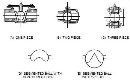
FIG. 10 Ball valve.
The ball valve has greater capacity and lower cost than a similar-sized globe valve, and its throughput is twice that of the same size globe valve when the pressure drop is low.
The full-bore ball valve is not used for throttling and control applications but generally for on off applications. It has a sluggish response for the first 30 percent of its travel, but will operate at a higher dp than a partial ball valve since it divides the valve pressure drop into two steps.
The characterized ball valve consists of a partial sphere when it is opening up. It presents a tri angular shape that makes it suitable for liquids that have solids in suspension. Its flow characteristics are equal percentage, and it provides good rangeability. This makes it an all-round general-duty valve, and it is actually taking over some of the globe valve's applications. The characterized ball valve is less expensive, lighter, and easier to install and maintain than a globe valve of similar duty. With its contoured notch shape, the characterized ball valve is used for modulation when the valve has a solid connection between the stem and the ball.
A variation of the ball valve is the plug valve. Plug valves are similar to ball valves, have linear or equal-percentage characteristics, and have a 1:10 to 1:100 rangeability. However, their high friction makes them less suitable for modulating service.
Ball valves are good for slurries and fluids with suspended solids because of their straight through design and self-cleaning action. They have excellent packing sealability, low weight, a small number of parts, and a simple design. With these valves, the valve stem is not alternately wetted and exposed to air (due to the rotary motion), which minimizes the effect of corrosion.
In addition, ball valves can provide tight shutoff (with PTFE seals).
However, ball valves have limited cavitation and noise protection, their pressure drop ratings are limited, and the dp across the valve generates a strong side thrust on the operating shaft.
Butterfly
The butterfly valve (see FIG. 11) consists of a cylindrical body with a disk (the closure member) mounted on a shaft that rotates perpendicularly to the axis of the valve body. Louvre dampers have the same characteristics as butterfly valves. Butterfly valves have large capacities, and the only obstruction to the flow is the disk. The torsional force on the shaft increases as the valve opens until it reaches 70 to 75° open; after that, it tends to reverse. Rubber seating gives butterfly valves tight closure. However, these valves may tend to stick in the closed position unless eccentric disks are used.
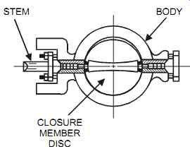
FIG. 11 Butterfly valve.
The most common butterfly design is the flangeless (wafer) type. Typically, butterfly valves are limited in temperature range and should be sized so they can operate within 20 to 60° travel for good controllability. Butterfly valves offer high capacity at low cost. They have a small body mass (and so weigh little), are easy to install, and have an excellent packing sealability. In addition, they are simply designed and have a small number of parts. The butterfly valve's design eliminates the valve stem's alternate wetting and exposure to air, which minimizes corrosion. These valves have a tight shutoff capability (if they are lined) and can be used as a modulating control valve.
However, butterfly valves have a limited pressure-control range, and their pressure-drop ratings are limited. They are not used in cavitation or noise applications or for slurries or dirty/ solid-bearing fluids. The dp across the valve generates a strong side thrust on the operating shaft.
Eccentric Rotary Plug
The rotary plug for this valve (see FIG. 12) provides an eccentric motion that produces capacities and performance close to those of the cage-guided globe valve. The eccentric rotary plug valve has a normal operating travel of 50° and is available in flanged or flangeless construction.
The eccentric rotary plug valve's metal-to-metal seating provides good shutoff, with no rubbing contact in the seat ring. The positive seating action and tight shutoff can be obtained with relatively low forces. This type of valve has a relatively high capacity, offers reasonable cost, and can handle corrosive fluids. The eccentric motion of the plug requires low actuating forces (as compared to butterfly valves), which reduces the torque requirements for the actuator. The eccentric rotary plug valve is available for flow in either direction, which provides a stable flow operation for either flow-to-open or flow-to-close.
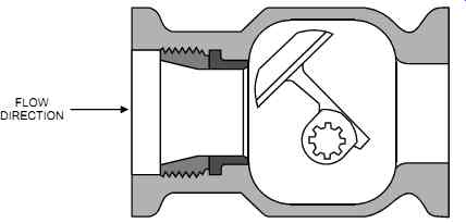
FIG. 12 Eccentric rotary plug valve.
The eccentric rotary plug valve has some tendency to cavitate because of its high-pressure recovery in the "flow-to-close" mode. It also has some limitation in dp capability because of stability considerations. Typically, it requires a long-stroke, spring-opposed, rolling diaphragm actuator.
Trim
Valves control the rate of flow by introducing a pressure drop. Most of this pressure drop is developed across the valve trim. For a typical globe valve, the trim consists of the seat and plug. The seat, plug, and stem are generally made of 316 SS for pressure drops up to 100 psi (700 kPa) and hardened alloy steel for higher pressure drops, unless the process specifications require materials of higher quality.
The valve trim provides the valve shutoff capability as well as its flow characteristics. A valve's flow characteristics involve the relationship between the stem position and the flow through the valve (i.e., the flow behavior of the valve as it is stroked). The theoretical flow characteristics of a valve are known as the "inherent flow characteristics" (see FIG. 13).
They are determined by the design of the plug under test conditions and are based on a constant pressure drop. The actual flow characteristics under operating conditions are known as the "installed flow characteristics." They are subject to the varying pressure drops that occur in the line as the flow varies. Typically, under the varying differential pressures that result from varying flows, the inherent equal-percentage characterized valve will behave like a linear valve, and the linear valve will tend to behave like a quick-opening valve.
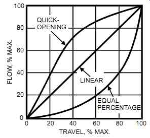
FIG. 13 Inherent flow characteristics.
The three most common trims are the linear, the equal percentage, and the quick-opening (see FIG. 14). With the linear trim, the flow coefficient (Cv) is directly proportional to the valve opening. With the equal-percentage trim, equal increments of valve travel provide an equal-percentage change in flow coefficient. For example, if when the valve opens from 40 percent to 60 percent the Cv doubles, then when the valve opens from 60 percent to 80 per cent, the Cv will also double. With the quick-opening trim, large increases in Cv occur as the valve opens, and only small Cv increases will occur as the valve reaches its fully open position.
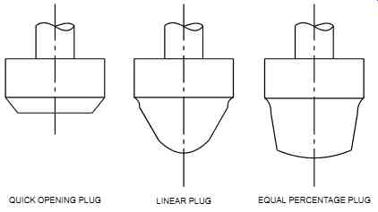
FIG. 14 Profiles of different plugs for globe valves.
In general, linear valves are used in situations where the controlled process variable is proportional to the flow and where the pressure drop across the valve is relatively constant. Equal percentage valves are used where the valve pressure drop decreases as the flow increases. They are also used in situations where the major system pressure drop is not across the valve, or when valve oversizing will occur. Quick-opening valves are typically used for on-off operations only.
Actuators
The actuator provides the power to vary the orifice area of the valve (i.e., opening and closing the valve) in response to a signal received. The stem carries the load from the actuator to the trim assembly. Actuators are typically selected by the valve vendor who supplies them pre mounted to the valve. There are two types of actuators: linear and rotary.
The three most common types of linear actuators are the spring and diaphragm assembly, the air piston, and the electric motor. The spring and diaphragm (see FIG. 15) is relatively low in cost, inherently fail-safe, and simple and reliable, with few moving parts. However, it has limited power, limited seat shutoff capabilities, and slow operating speed. In addition, the spring and diaphragm may not handle high variations in stem load (i.e., it lacks stiffness).
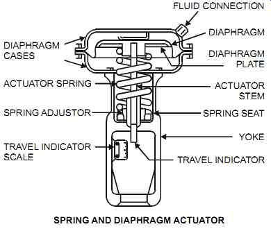
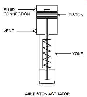
FIG. 15 Linear Actuators.
The air piston (see FIG. 15) provides high torque (or force) and has a fast stroking speed.
In addition, it provides a high power-to-weight ratio, has few moving parts, and has an excellent dynamic response. It will also handle high differential pressures and provide high shutoff capability. However, the air piston typically requires a valve positioner.
The electric motor is generally used with a gear box and does not need air or a current-to-pneumatic converter (I/P). In addition, it provides a high force and is reversible. This type of actuator generally requires that the end-of-travel be adjusted and that torque-cutout limit switches be installed in order to avoid damaging valve parts.
The two most common types of rotary actuators are the rack and pinion and the quarter turn rotary. The rack and pinion type uses a linear actuator and translates its linear motion to a rotary motion. This can be done by mounting a rack on the actuator's stem and a pinion on the valve's stem.
The quarter turn rotary actuator, also known as the vane type actuator, consists of a vane enclosed in 90º pie shaped casing. Air pressure on one side of the vane will move the vane, which in turn will rotate the stem. An opposing spring counteracts the vane's moving action.
Quarter turn rotary actuators are used in applications where high forces for valve movement are not required.
Response Time
Actuator response time varies according to the size and type of the actuator. For example, a spring diaphragm with a positioner may require 8 seconds for a 2-in. (50 mm) valve and 1 minute for valves larger than 6 in. (150 mm). These values are reduced if a booster is added.
A piston actuator may require 0.2 seconds for a 2-in. (50 mm) valve and 2.5 seconds for valves larger than 6 in. (150 mm).
Air Volume Boosters
Air-volume boosters are used to supply air where high-speed or high air pressure (up to 250 psig [1700 kPag]) action is required. For example, a valve with a booster will increase performance speed three to four times when compared to a valve with a positioner only.
Valve Positioners
Despite its name, a valve positioner is in reality an actuator's "position controller" that acts as a secondary controller whose feedback is the position of the stem (refer to Section 8 for more on cascade loops). Positioners are typically supplied with three pressure gages (supply, input, and output). Valve positioners are generally used in the following cases:
• To accurately position the valve stem; for example, when the pressure differential is 200 psi (1400 kPa) and higher
• When the stem-packing friction has an effect on the valve's response to an input signal
• To change the control valve's characteristics
• To provide split-range operation (use the same characteristics and travel for both valves)
• To increase the valve's speed of response
• To provide necessary air pressure for high-pressure applications
• To reverse the valve's action (direct or reverse)
• To increase shutoff capability
• To control springless actuators (double-acting pistons)
• For three-way and rotary throttling valves
• On valves that are 4 in. (100 mm) and larger
Handwheels
Handwheels are used as a way to provide manual control, such as for overrides or in case of power or signal failure. In most loops they are not required. If a handwheel is essential to an operation, the plant should ensure that it is accessible and can be maneuvered by a single person.

