AMAZON multi-meters discounts AMAZON oscilloscope discounts
Overview
The installation of instruments, control systems, and their accessories follows the final stage of the engineering design. The installation is then followed by commissioning and plant startup. It is important to prepare an installation specification that defines the owner's requirements-this prevents misunderstandings, extra costs, and construction delays. The content of such a specification typically covers the following topics: code compliance, scope of work, installation details, equipment identification, equipment storage, work specifically excluded, approved products, pre-installation testing, execution, wiring, tubing, and checkout. All of these are discussed in this Section. It should be noted that the following guidelines apply to the majority of installations. Certain harsh or special environments may need additional requirements.
Code Compliance
It should be the responsibility of the installing contractor to ensure compliance even though the owner produced all engineering documentation and may be reviewing and approving all installation. All equipment and installation must comply with the codes in effect at the site. There will be cases where the drawings or specifications call for material, workmanship, arrangement, or construction of quality that is superior to that required by any applicable codes. In such cases, the drawings and specifications should prevail. Otherwise, the applicable codes and standards must always prevail.
To comply with local codes and especially with insurance requirements, all electrically operated instruments or the electrical components incorporated in an instrument should be approved and bear the approval label (UL, FM, CSA, etc.). Modifications to an approved piece of equipment may void the approval.
Scope of Work
An installation contractor's scope of work typically includes all items of instrumentation and control systems shown in the documentation supplied with the installation specification.
Depending on the size and complexity of the project this set of documents typically includes the following: P&IDs, instrument index, instrument specification sheets, loop drawings, inter lock diagrams, installation details, vendors' data, location drawings, related piping drawings, and location and conduit layout drawings. This documentation is used by the installing con tractor to bid on the job and to do the work. In addition, to avoid future unwanted surprises, it is strongly recommended that the contractor visit the site before tendering a bid to understand all conditions and requirements that must be met in carrying out the work. This includes reviewing and accepting the safety requirements in effect at the plant. The contractor is responsible for reviewing all documentation and equipment received before commencing the installation work. Should there be inconsistencies (and there normally are), the contractor should immediately notify the owner, who then should decide on a solution.
All instrumentation devices listed in the instrument index should be mounted and connected by the contractor to form a complete operating system. A manufacturer, such as a panel assembly shop, may ship pieces of the equipment and instrumentation separately, but these pieces should be installed and connected by the contractor.
It is expected that the installation work will be carried out by certified and trained personnel with adequate supervision and the equipment necessary to complete the work. The owner may require the contractor to produce evidence of the personnel's certification and training and to ensure that the construction crew (and in particular their supervisor) will remain on the job until completion.
In situations where an electrical certificate of final inspection must be furnished to the plant, the contractor should apply for it and pay all fees required for the certificate.
During construction and commissioning, changes to the original drawings do occur. They must be recorded by the contractor on a set of drawings that is handed over to the owner before final inspection of the work. These marked-up drawings and documents form the basis of the future "as-built" documentation.
Installation Details
All field-mounted instruments should be installed and connected in such a way that the instrument can be maintained and removed for servicing without having to break fittings, cut wires, or pull hot wires through rigid or flexible metal conduit. Sufficient clearance around the instruments must be allowed to permit them to be removed without disturbing other equipment. It is also expected that the contractor will provide the necessary unions and tubing connections to all instruments. In addition, to prevent debris or paint from getting at the instrument, all field mounted instruments, once installed, should be protected by heavy plastic bags until the owner gives final acceptance. Wherever dry air purging and/or heating are specified for an outdoor instrument enclosure, they should be activated as early as possible to protect the instruments.
The location of instruments and control equipment is generally identified on a location drawing (see FIG. 1). This drawing is generally a plan view of the facility, showing the location of individual I&C equipment with their respective elevations. Some companies use the piping drawings (instead of separate location drawings) to indicate the location of I&C equipment.
Piping drawings are typically not produced by the I&C discipline (it's a piping/mechanical engineering document). These drawings normally show the equipment and process lines as well as the connection to all field instruments (complete with elevations and tag numbers). The information on these drawings can be used in the instrumentation and control activities. This approach has two main advantages. First, fewer drawings are prepared and cost is reduced. Second, having only one drawing that shows both process equipment and instrument location and process connection avoids errors that occur when two drawings show the same information.
The details of the instrument connections (i.e., instrument air, power, wiring, etc.) are shown on the appropriate drawings, such as the instrument loop diagrams or specific instrument installation details.
The following points should be considered when installing I&C equipment:
• Plant maintenance personnel must have access to the instruments. Therefore, all instruments, including vessel or piping connections for sampling or for sensing elements, are located so they are accessible from structural platforms or grade.
• Access from permanent ladders should be restricted to small instruments (such as pressure gages, dial thermometers, or thermocouples), to cases where location cannot be changed to permit access from a platform or grade, and to cases where one person can easily carry the instrument.
• Process tubing should be designed and routed to prevent sediments from being deposited inside the tube or in the sensor housing (also refer to section "Tubing" later on in this Section).
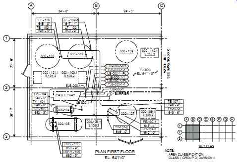
FIG. 1 Typical location drawing.
Equipment Identification
All instruments and control equipment, including junction boxes, should be identified by the equipment tag number. This should read the same as the number that is shown on the documentation (see Section 2 for further information on equipment identification). Tags are generally affixed to the instrument body or housing wherever possible and to the instrument support or adjacent tubing only when unavoidable. The tag should not be placed where routine maintenance would require that the tag be removed. In addition, all wiring should be identified with suitable nonconductive and abrasion- and solvent-resistant markers, with the wire numbers as shown on the documentation (i.e., on loop diagrams and interlock diagrams).
Most plants have their individual way of color coding the wires, from a simplified black (for phase or positive conductors) and white (for neutral or negative conductors) to a more complex coding system where each voltage and application has an individual color. However, in all cases, earth ground (if insulated) is green, and thermocouple extension wires use the ANSI color code. For intrinsically safe (IS) wiring, a bright blue color is the norm, so this color should not be used on any other circuits. This color may be take the form of a blue stripe on wires whose colors follow the general scheme described earlier. Conduits, cable trays, terminal blocks, and field junction boxes must also be identified with a bright blue label bearing the leg end "INTRINSICALLY SAFE."
Finally, all temporary jumpers that must be removed when commissioning, testing, or startup is completed must have a unique color, for example, an orange colored wire, for identification purposes.
Equipment Storage
On some construction sites, the installation contractor is expected to provide a separate adequate indoor storage space for instruments that require protection from excessive temperature or humidity. This space sometimes must be heated or air conditioned. Instruments, wherever possible, are kept in their original shipping cartons until installed. It is good practice to maintain a separate storage space apart from the areas where non-instrumentation equipment is stored.
Depending on the project's management and scope, the installation contractor may be responsible for receiving, unloading, safekeeping, and storing all materials and equipment supplied.
When accepting deliveries, the contractor should inspect the equipment and materials against the instrument index, specifications, and purchase orders to ensure that quantity, type, ranges, and so on, are as specified. If there are discrepancies, they should be immediately rectified since at this stage, time is of the essence.
Work Specifically Excluded
The owner should clearly and separately identify exceptions to the scope of work. It is common practice on construction sites to have the piping/mechanical contractor install all in-line devices, such as control valves, orifice flanges and plates, in-line flowmeters, thermowells, as well as all impulse piping from the process up to and including the first block valve. This information should be detailed on the piping drawings to avoid misunderstandings, project delays, and extra costs.
To prevent damage to the instruments, most of which are relatively delicate (and expensive), all in-line devices must be removed when the piping is being flushed and cleaned and then reinstalled. In addition, during hydraulic tests on the process pipework, instruments should be disconnected to ensure that the isolating valves are leak proof. In no case should any instrument, other than control valves and thermowells, be subject to test pressures.
Approved Products
It is quite common for a client to specifically state to the contractor which products are approved for use on the client's project. Such a list of products can include electrical and pneumatic junction boxes, power and control cabling, terminal strips, rigid conduits and flexible conduits, conduit fittings, tubing, tube fittings, and so on. An actual list of approved products is typically included in the installation specification to guide the contractor.
Pre-installation Testing
Pre-installation testing ensures that each instrument as received from the vendor is supplied in accordance with its specifications, is functionally correct, and is in working order. To maintain control of a project, it is good practice for a client to require a schedule from the contractor that defines the overall sequence of instrument testing on a project.
With a few exceptions, instruments should be subjected to a pre-installation test that commences as soon as practicable after the instrument is received. The tests, when done on site, should be performed in the manner described by the manufacturer's documentation, with any adjustments also made in accordance with the manufacturer's instructions. The pre-installation calibration of instruments requires the availability of a fully equipped lockable workshop and a clean dry environment for the equipment. In some cases, instead of on-site pre-installation testing, the owner may rely on a certified test done by the vendor before the instruments are shipped to the site.
Before calibration commences, a comprehensive list of the test equipment to be used must be assembled. This test equipment should have a standard of accuracy at least ten times better than the manufacturer's stated accuracy for the instrument to be tested and be backed with calibration certificates that are up to date and available for inspection.
The owner should be immediately informed of any defects that cannot be rectified or any instrument that cannot be calibrated within a reasonable time. In areas with cold temperatures, the tests should be carried out on electronic instruments only after an adequate warm-up period.
Instruments are in most cases tested at 0 percent, 25 percent, 50 percent, 75 percent, and 100 percent in the up-scale and down-scale directions. If necessary, they are adjusted until the accuracy conforms to those limits stated by the manufacturer. After testing, all connections and entries must be sealed to prevent moisture and dirt ingress.
Execution
It is extremely difficult for an installation specification and its reference documents to cover each and every installation detail. The installing contractor is expected to be familiar with the codes and current good practices for the installation of instruments and their related hardware.
The contractor is also typically expected to provide and install all peripheral items such as clips, supports, clamps, brackets, and stands as well as all necessary welding, painting, wiring, junction boxes, tubing, and fittings that are required to complete the installation and connect instruments as required by suppliers and by the owner's installation specification.
Instruments should only be mounted when all heavy mechanical work adjacent to the location of their installation has been completed. This should be clearly stated in the installation specification. Instruments and junction boxes should be mounted level and plumb and so as to pro vide accessibility and protection from mechanical damage, heat, shock, and vibration. They should not interfere with any structure, other equipment, piping, or electrical work. In addition, instruments once installed should not create an unsafe condition (such as sharp edges or protrusions) and should not obstruct walkways or other means of access provided for maintenance or process use, such as access for forklift trucks and cranes.
Instruments, impulse lines, tubing, or wiring should not be attached to process lines or process equipment except for equipment designed for process connection, such as in-line transmitters, gages, or control valves. Where instrument items are connected to piping or equipment, they should not be installed so damaging or undesirable stress is placed on the piping, equipment, or instruments. Most important, piping and equipment must not be supported by items of instrumentation or their accessories. Brackets and supports must be used where needed.
Field-mounted instrumentation and junction boxes are frequently mounted on building columns and walls. All mounting must be done in compliance with the equipment vendor's recommendations and quite often it is done through the use of metal framing (such as Unistrut's). Support stands made of painted mild steel pipe are provided when it is impractical to mount instruments on columns and walls. Such support stands should be attached to the building structure, beams, columns, or other permanent structural members and should not be attached to handrails, floor grating, process equipment, piping, vessels, conduit, or instruments. Where drilling in concrete, the contractor must avoid reinforcing steel and embedded conduits. If in doubt, the contractor must contact the plant engineer before any drilling starts.
Painting should be done according to existing plant specifications (typically, first primed then followed by two coats of paint).
Wiring
In the world of instrumentation and control, electrical power is provided at a relatively low voltage, typically 120V AC or 24V DC. In most cases, there are four types of instrumentation and control wiring.
1. Very low-level DC analog signals, such as for thermocouples, strain gages, pH sensing, etc.
2. Low-level DC analog signals (4-20 mA at 24V DC)
3. Low-voltage power wiring and low-voltage discrete signals (at 24V DC)
4. High-voltage power wiring and high-voltage discrete signals (at 120V AC)
The installing contractor should run each of these four types in a dedicated multiconductor or conduit. Shielded wiring should be used for types 1 and 2. A gap should be maintained between each of the four types. This gap may be set by plant standards, and some plants have determined that a 1 ½ ft (0.5 m) is a safe and conservative distance for all applications under 100 kVA-an assumption valid to most instrumentation and control applications. Other plants abide by the following rules:
-- In a contiguous metallic raceway or conduit, allow a minimum of:
• 3 in. (0.08 m) if the 120V AC wiring carries less than 20A,
• 6 in. (0.15 m) if more than 20 A but less than 100 kVA, and
• 1 ft (0.3 m) if more than 100 kVA.
• In a non-contiguous metallic raceway or conduit allow a minimum of
• 6 in. (0.15 m) if the 120V AC wiring carries less than 20A,
• 1 ft (0.3 m) if more than 20 A but less than 100 kVA, and
• 2 ft (0.6 m) if more than 100 kVA.
In addition, a minimum distance of 5 ft (2 m) should be maintained between power transformers (and switchgear) and Types 1, 2, and 3 instrumentation and control wiring.
Quite often, types 2 and 3 can be run in the same conduit. In that case, type 3 wiring should be shielded as well. To avoid interferences arising between low-voltage and high-voltage cables, they should cross only at right angles and be kept physically separate on cable trays. For any other type of wiring, such as fieldbus or data highway, the installation must closely follow the vendor's recommendation.
Good grounding is vital to the installation of modern electronic-based equipment. First, individual shields in a multiconductor cable must be connected to the shields of the individual pair of cable to which they connect. The shields must not be grounded to the structure or to each other at the junction box. At the instrument end, no connection should be made to any shield, foil, or drain wire. In addition, the shield is typically not connected to the signal ground as this would introduce noise to the signal. In all cases, the designer should carefully follow the recommendations of the equipment vendor. The contractor must follow the grounding requirements as shown on the loop drawings, which typically show the grounding at the input/output cabinets. Sometimes field grounding exists, as designed by the equipment vendor, typically on analyzer systems. In these situations, a loop isolator is required to prevent ground loops from forming. (See "Grounding" in Section 1 for further information.)
Cable runs should be positioned clear of process pipes, service pipes, ventilation ducts, hoist blocks, overhead cranes, and other similar equipment. They should be routed neatly to run either vertically or horizontally and not diagonally across walls, ceilings, or floors. Cables should enter into panels on the panels' underside to reduce the risk of water or other liquids seeping into the panel and damaging the electronic equipment. Where side entry is unavoidable, these cables should incline downward away from the equipment to ensure that water does not flow toward the cable entry point. Cable entry into the panel from its top must be avoided.
Also, drilling in a control cabinet should be avoided since metal chips can land on the electronics, causing short circuits. If drilling is unavoidable, then the installer should ensure that all electronic components are well covered (e.g., with a plastic sheet) before drilling starts.
All field-run conduits and cables are generally shown on the location and conduit layout drawings, which include details on the identification and number of wires. These drawings typically also show the location, elevation, and size of cable trays, junction boxes, and control/interlock panels.
Where redundant or triplicate channels are implemented, the different components (cable pans, conduits, junction boxes, equipment racks, etc.) should be physically separate. A minimum distance of 12 to 20 inches (0.3 to 0.5 m) is typically required between the different channels.
Tubing
In electronic-based modern control systems, tubing is typically used for supplying instrument air to control valves and for process connections (also known as process tubing). Other tubing is used in hydraulic systems, but this topic is outside the scope of this handbook.
Air-actuated control valves require an air supply that is typically supplied by an individual shutoff valve that allows independent shutoff. The air supply take-off from the major supply header should be made from the top or side of the header or branch. To avoid leakage problems, tube connections and fittings should be kept to a minimum and preferably should not be permitted in tubing runs.
Process tubing must conform to, or exceed, the process/utility piping code specification with respect to design temperature and pressure as well as materials of construction. In most applications, process tubing is made of stainless steel and either 1/2 or 3/4 in. (10 to 20 mm) in size, depending on the application. On gas and liquid lines, the tubing is sloped continuously, with an appropriate grade of one in ten or greater. Sloping ensures that the gas and liquid go to predictable locations in the tubing. On steam lines, the tubing must remain horizontal to ensure a steady liquid head.
Tubing should be sufficiently supported to avoid vibrations and sagging. The support interval is typically every 3 ft (0.9 m) as well as before and after each bend. Where concentrated load exists on the tubing (such as valves)-supports should be located as close as possible to that load. Where straight runs exist, the supports should permit tubing movement. Exhaust tubing should always be routed downward.
Straight tube runs should not be installed between fixed fittings. At least one 90º bend is required to allow for motion and thermal expansion. A flexible hose should be used where too much vibration or relative motion exists.
Tube bending should be done with a tube bender and the tube should not be kinked or flattened. The minimum bend radius varies with the tube material, thickness, and diameter (refer to the vendor's recommendations). Tube cutting should be done with a sharp tube cutter and the end of each cut should be square.
No cutting oil should be used in the cutting process. All tube cuts should be deburred on the inside and outside of the tube and the exterior surface of the first two inches (5 cm) should be free of any visible defects (e.g., kinks, flat spots, and scratches). Male pipe threads should have a sealant-however, the use of thread tapes should not be allowed.
For a typical gas installation with no condensable fluids, the measuring device should be located above the process line and the process tap on the top or side of the line (see figure 2). All horizontal lines should be sloped to allow any trapped liquids to flow back to the pro-cess. For typical liquid installations or condensables such as steam, the measuring device should be located below the process line and the process taps to the side of the line (see FIG. 3). All horizontal lines should be sloped to allow trapped gases to flow back to the process.
On condensable fluids, filling tees are required to allow a stable static head to be created. Some corporations will develop individual installation detail drawings that give a detailed description of the material needed for the installation (see FIG. 4). Other corporations generate a handful of "typical installation details" and rely on the capabilities and experience of the installing contractor.
Process tubing that contains liquids that can freeze should be protected by heat tracing. Tubing susceptible to plugging should be provided with suitable connections for cleaning, while tubing that handles gases that contain moisture should be provided with suitable drains, settling chambers, or traps. So that calibration and occasional checks on the instrument's output may be made without disconnecting the instrument, a tee may be located between the instrument shut off valve and the instrument, with a threaded plug (or shut-off valve) on the vent side.
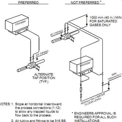
FIG. 2 Typical gas installation.
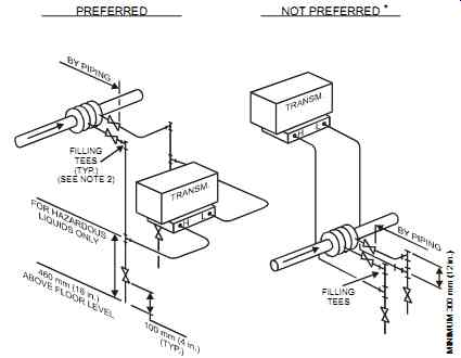
FIG. 3 Typical liquid installation.
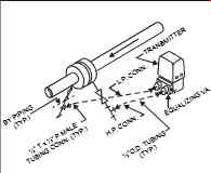
FIG. 4 Typical installation detail.
Process tubing is tested as part of and under the same conditions as the process/utility piping system. Before and after testing, impulse lines should be flushed and blown down with water or air to remove all contamination.
Checkout
After the installation and before the owner has accepted the system, a "checkout" is performed.
The installing contractor should check the operation of each completed loop by simulating the process and events. Loop checking is performed from the process sensor to the control room and out from the control room to the final control element. Records should be kept of the final checks to instruments and control systems. These records could take the form of individual signed-off instrument specification sheets or loop diagrams.
Loop checkout also includes visually checking that:
• accessibility to equipment is adequate.
• equipment is correctly supported.
• painting and protection against corrosion is complete.
• correct materials are used.
• terminal, cables, tubes, and equipment are identified and labeled correctly.
• segregation and minimum bending requirements are implemented.
• all cables and wires are properly terminated and supported.
• correct cable glands (type and material) are used.
• all equipment covers are in position and all unused ports are plugged.
• all equipment is properly grounded and connected to the correct supply voltage.
• the complete electrical installation complies with the appropriate codes and standards.
• the requirements for the installation are met (e.g., meter-run straight lengths, location and orientation of instrument process tapping points, etc.).
Loop check activities also include the following:
• Cleaning the air tubing by blowing it out with clean, dry instrument air
• Performing tubing pressure tests and ensuring that all connections have been made correctly
• Checking all field instruments at three points (0%, 50%, 100%) and ensuring that each individual instrument is in good working order. For thermal systems, a two-point check should be sufficient (one or two temperature baths may be required).
After the installation and checkout are completed, the installing contractor should compile the certificates, records, manuals, instruction sheets, as-built drawings, sketches and diagrams, and other relevant data applicable to the completed work and hand them to the owner. Upon receipt of the signed-off records, the owner completes the acceptance stage, signifying the completion of the installation work.