AMAZON multi-meters discounts AMAZON oscilloscope discounts
Overview
Engineering design and documentation activities can be split broadly into two parts: front-end engineering and detailed engineering. Front-end engineering will vary according to the project size and conditions, but in the end, its content must define the project requirements, engineering standards, plant guidelines, and statutory requirements that are in effect at the site, setting the foundation for a successful detailed engineering.
Detailed engineering encompasses the preparation of all the detailed documentation necessary to support bid requests, construction, commissioning, and maintenance of the plant. In the present business environment, the size of corporate and plant engineering staff are generally at minimum levels, so the detailed engineering phase on large projects is frequently given to an engineering contractor or to an equipment supplier. In some cases, the instrumentation and control (I&C) engineering portion of a project is contracted out as part of a larger engineering package that includes other disciplines such as civil, electrical, mechanical, and the like.
AMAZON multi-meters discounts AMAZON oscilloscope discounts
Front-end Engineering
Front-end engineering is the first step in engineering design. It defines the I&C requirements and covers the preparation of the engineering data that is needed to start detail design. This phase, from an I&C point of view, typically parallels the preparation of preliminary process and instrumentation diagrams (P&IDs)-sometimes known as engineering flow diagrams- and the completion of hazard analysis for the process under control.
The hazard analysis is an essential part of the design activities. However, since it is not normally an activity led by I&C engineering, it will not be discussed in this handbook. If the reader requires additional information on this subject, it can be found in OSHA's Part 1910, Appendix D, and in other pertinent publications.
In general, three documents should be prepared during the front-end engineering phase and completed before the start of detailed design. They are: the P&IDs, the control system definition (which may include a preliminary instrument index), and the logic diagrams. On large projects, two additional documents may be required: a scope-of-work definition for the engineering contractor that will do the detailed engineering, and a scope-of-work definition for the supplier of packaged equipment, such as water treatment facilities, boilers, compressors, and so on.
Front-end engineering documents must be updated as changes are made during the project, and changes do occur. Once these documents are approved and agreed upon, no changes should be implemented without prior approval from the project manager and the assigned control engineer (or control supervisor, depending on company policy). The reason for this is to maintain control of changes, since these documents are the guidelines for the detailed engineering that affects contractors and vendors, and therefore impacts the schedule and budget.
Detailed Engineering
Detailed engineering must be based on the statutory requirements in effect at the site and on the front-end engineering. The documentation produced under detailed engineering will vary with the complexity of the process, the project's requirements, and the plant's philosophy and culture. The following is considered to be the minimum technical information for the field of I&C; engineering management must decide whether any additional documents are required:
• Instrument index
• Process data sheets
• Instrument specification sheets, including calculations (for control valves, orifice plates, etc.)
• Loop diagrams
• Interlock diagrams
• Control panel specifications (including an overall layout; see Section 12 on enclosures)
• Control room requirements (see Section 11 on control centers)
• Manuals for programmable electronic systems (DCS, PLC, PC, etc.)
• Alarm and trip-system documentation and testing procedures (see Section 10 on alarm and trip systems)
• Installation specification (see Section 15 for further details on installing instruments) In addition to these documents, a location drawing is prepared that shows the location of all I&C devices (for further information, see FIG. 1 in Section 15). Also, two additional documents that are generally not prepared by the I&C discipline but are of prime importance to the I&C detailed design phase: piping drawings and location and conduit layout drawings. They are described in Section 15 under "Installation Details" and "Wiring." Document Quality
The front-end and detailed engineering must meet and maintain a certain level of document quality. As a starting point, the plant must ensure that each document carries the required identification and cross-reference information. Common practice is to show drawing identification information in the bottom-right corner of a drawing in an area called the title block. For a specification, this information is typically shown on the front page.
Document identification typically consists of the following content:
• Plant name and location
• Process area (or name)
• Document number
• Document title
• Date document originated and name of the person approving it
• Date of revision, name of person approving the revision, and a condensed revision description
When the document is revised, it is also recommended that the nature of any changes be identified. The changes should be listed chronologically, so future users can understand the purpose and scope of previous modifications. Typically, when documents are issued for construction the revision number starts at 0. Before that they tend to have letters (A, B, C, etc.), reflecting the engineering revisions. If a section is not finalized, it could be circled and the word Hold written inside the marked area. This "Hold" should be resolved and removed before the document is issued for construction.
To conform to the quality standard, such as ISO 9000, that some plants adhere to, the plant must have a system of documentation control in place for identifying, collecting, indexing, filing, storing, maintaining, retrieving, and disposing of pertinent engineering records. This applies to both front-end and detailed engineering documentation. Using some of the ISO 9000 guidelines as general rules
• the latest issues of the appropriate documents must be available at all pertinent locations.
• documents must be reviewed and approved by authorized personnel before they are issued and according to a procedure. Authorized personnel must have access to the background information upon which they may base their decisions.
• obsolete documents should be clearly identified and quickly removed from all users.
Following the plant's construction, commissioning, and startup, a complete set of documentation should be revised, reflecting the "as-built" condition, for the purposes of operating and maintaining the plant. In addition, all documentation should be maintained as changes occur throughout the life of a plant's control system.
Process and Instrumentation Diagrams (P&IDs)
The P&ID is an essential document in process industries, whether it goes under the name "engineering flow diagram" or "piping and instrumentation diagram." It is a drawing that rep resents the process in the plant and how the major components (equipment, piping, and instruments) are connected together. It defines the scope of a project, acts as the foundation for all design activities, and is the basis for the detailed design and operating documents. P&IDs are used to aid communication within the engineering team, plant operation, maintenance personnel, and contractors.
P&IDs are usually developed from process flow diagrams, mass balances, and the plant control requirements. They are generally created by a team that consists of at least a process engineer and a control engineer. However, the process engineer is typically the "owner" of the P&IDs and the one who controls all approvals and modifications to the document. It is very confusing (not to mention wasting money and time) to have users work from different versions of the same P&ID. Good engineering practice requires that a hazard and operability study (or similar exercise) follows drawing generation and changes, and that procedures exist for handling revisions effectively.
P&IDs typically show the following types of information:
• Plant equipment, including maximum, normal, and minimum levels in vessels. Where possible, it is good practice to represent the relative size, shape, and location of the actual equipment in the plant, including the location and size of tank nozzles, manways, connections, and the like.
• All pipelines, valves, bypasses, relief valves, vents, drains, and in-line devices such as check valves, filters, and reducers. Also, sloping lines (showing the amount of slope), insulation, and tracing (showing the type-steam or electrical). If heat tracing is self-limiting or thermostatically controlled, it should be noted on the P&ID.
• The set pressure for all relief valves, rupture disks, pressure regulators, and temperature regulators.
• All motors (and in some cases their voltage and horsepower) and interlocks. A description of the motor start/stop philosophy for the plant should be included in the control scope definition or in the notes section of the P&IDs.
Controls and instrumentation, including:
• indication of whether the instruments are in-line devices or remote mounted (and in some cases showing the instruments' connections to the process)
• instrument purging, tracing, and insulation
• the major function of the instrument loop (leaving the details to other documents to preserve precious P&ID drawing space)
• the signal transmission method and control valve actions on air/electrical failure, that is, fail-open (FO), fail-closed (FC), or fail-locked in last position (FL)
• all interlocks, with their descriptions shown in other documents such as logic diagrams unless they are simple enough to describe in writing.
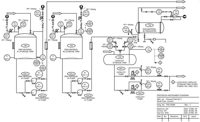
FIG. 1 Process and Instrumentation Diagram.
The equipment layout on a P&ID usually follows a left-to-right sequence on the drawing (see FIG. 1). Notes are typically added on the right side of a P&ID above the title block. Notes are used to describe items on the P&ID, to refer to other documents, and to provide guidance in understanding the information on the P&ID.
For clarity, P&IDs showing the supply and distribution of utilities and services such as instrument air, steam, and cooling water are normally drawn separately from the main process P&IDs. The cut point on each utility line is marked where it becomes part of the process P&ID.
Vendor-supplied packages are drawn as rectangles that contain references to the detailed vendor drawing(s). This approach is essential on P&IDs that are loaded with too much information and where drawing space is at a premium.
Any item should be shown only once on the P&IDs. If, for clarity, an item needs to be shown twice or more on different P&IDs, then on the other P&IDs it should be shown in dotted lines.
From an I&C point of view, the symbols used on P&IDs should be based on an established corporate standard. If none exist, the symbols should then be based on ISA-5.1-1984 (R1992), Instrumentation Symbols and Identification (refer to Section 2 for further details). ISA-5.1 1984 (R1992) acknowledges that it is at the discretion of the user how much detail should be applied to a document. Generally, a P&ID should have sufficient detail to convey the functional intent of the loop and to enable the viewer to understand the means of measurement and control for the process. Because of space limitations on P&IDs, the full complement of instruments in a loop should be shown on other documents, such as loop diagrams and interlock diagrams.
As a rule, the control functions that must be shown on the P&IDs as separate elements are all in-line instruments, all hardwired interlocks and alarms, and all connections to the control sys tem. Functions that need not be shown on the P&IDs as separate elements are any elements that are not needed to convey the functional intent of a loop (but are sometimes shown for clarity or because of corporate culture). Examples include I-to-P and P-to-I converters (if they are part of the final control element) and intrinsic safety barriers.
To save precious P&ID drawing space, complex logic is kept outside P&IDs. Instead, logic diagrams are used to describe the detail logic of the trips and interlocks. See "Logic Diagrams" later in this Section for information on preparing logic diagrams.
A master P&ID or legend sheet is required to explain line identifications and describe all the symbols used on P&IDs. The detail shown on such a master P&ID will vary with corporate culture, but typically includes three main sections:
• A description of the symbols used for process equipment
• A description of the numbering system and identification used for the lines and for all pro cess equipment
• A description of the symbols and designations used to describe the instrumentation and control functions. See Section 2 on identification and symbols for further details on this subject.
Control System Definition
The control system definition is intended to ensure that all key aspects of measurement and control engineering are clearly and formally documented and agreed upon before detailed design starts and before the instrumentation and control equipment is purchased. The control system definition should be available for review by all concerned. This document provides a clear basis for the detailed design phase of a project, especially when that phase is undertaken by firms outside the organization such as engineering companies. Another major advantage of the control system definition is that it leads to a more accurate cost-estimating process.
The control system definition typically includes: a general description of the process, a description of the potential control system, the safety requirements for the particular application, a list of recommended vendors, and any other miscellaneous considerations such as electrical area classification and reliability requirements. The amount of information contained in a control system definition will change depending on a project's complexity and the corporate culture. Its size may vary from a few pages to a few hundred pages.
Process Description and Overall Plant Control Philosophy
The type of process to be controlled should be described, i.e., continuous, batch, manufacturing, or a combination. Management's requirements for data logging, production reports, efficiency reports, or links to other management information systems should be identified since they affect the potential control system from a hardware and software point of view. The number of operators who will be in the control room and in the plant, with their responsibilities, must be determined-this information will help define the extent of the operator interface via monitors and control panels. Even such detail as the expected response time by the operator should be established-this will allow a rational estimate of the number of alarms and of the expected operator response time in case of emergency or plant shut-down.
The operation's requirements for startup and shutdowns, for automatic versus manual operation, and for the location and function of operator interface equipment (e.g., main control room versus field control centers) must also be determined when the control system definition is pre pared.
Control System Description
The control system description section describes the potential control system (see Section 9 for further details on programmable electronic systems). First and foremost, the description must pay careful consideration to safety requirements so it complies with codes and good engineering practice. If special safety features are required, they may have to be implemented outside the basic control system, particularly where emergency stop circuits are implemented (see Section 10). Then, the system (being centralized or distributed) must meet the requirements of the process and of the operators. At this point, the control system designer should consult with plant operation personnel (the eventual system user) to understand their needs and problems.
The control system must be capable of accommodating future expansions and modifications, so these requirements must be estimated. In some applications, the effects of system malfunction (including failure of individual components, e.g., inputs, outputs, power supply) must be assessed. Therefore, the system's capabilities may include the need for redundancy at various levels of the control system, that is, at the controller, input/output, communication, and so on.
The control system must be capable of handling all the incoming data and outgoing controlled outputs at an acceptable rate. The control system may also have to interface with other systems such as vibration-monitoring systems, bar code readers, analyzer systems, and the like. As a result, the control system will require this interface capability both from a hardware and soft ware point of view. In the event of major malfunction, the operator must be capable of sorting out incoming alarms and trips as they start actuating in series (some people call it a "domino effect," others a "ricochet effect"). Therefore, the plant must consider categorizing and prioritizing alarms even for small control systems. They must be implemented for large ones. The designer of the control system also needs to assess if alarm and trip functions (and controller set points) should be protected from uncontrolled modifications or if the operator will be allowed to change such parameters at will.
The control system needs power to operate, therefore, the reliability and quality of the electrical power supply and of the instrument air supply are vital. If required, a backup must be implemented. In this case, an uninterruptible power supply (UPS) for the electrical power is required. For the instrument air, an air tank with sufficient retentive time would be added to the instrument air header system.
Another point to consider is how the operator will communicate with the plant. In some facilities where electronic equipment is susceptible to EMF noises, walkie-talkies are not allowed.
Signs to that effect are posted in the control room and near all control panels that house electronic equipment. Also, if computers and networks are to be installed and operated under unacceptable environmental conditions (temperature, humidity, vibration, and static), the plant must provide proper equipment protection (see Section 11).
And finally comes training. The level, quantity, and timing of training for involved staff (engineering, supervision, operations, maintenance) must be determined at the beginning of a project and funds allocated for it. At this point, a decision should be taken regarding the con figuration and programming. Will these activities be performed by in-house personnel or will they be contracted out? Each option has its pros and cons, both in the short and long terms.
It is worth noting that programmable electronic systems (PESs) provide tremendous capabilities for control but require that precautions be taken to minimize specific risks, such as system failure, environmental effects detrimental to the system, and uncontrolled hardware or soft ware modifications. All these risks can be minimized and in many cases almost eliminated with a well-designed, properly installed, and well-managed application (see Section 9).
Safety Considerations
The safety considerations section of the control system definition addresses the safety aspects of the control system (refer to Section 10 for further details). The exercise should start by identifying the main process hazards. It then looks at the required reliability of the control system, determines its failure mode, and deems it acceptable. Another item to consider in safety considerations is how quickly the plant wants the operator to respond in the event that the alarm/ trip is activated.
Recommended Suppliers
Quite often, certain suppliers will be recommended because of the plant's past experience with equipment reliability and vendor service. To facilitate plant maintenance, it is good practice to maintain uniformity of manufacture for any particular item throughout the project. Therefore, a list of approved vendors is typically generated at the early stages of design before contracts are awarded.
Other Considerations
This section considers the area classifications for a plant's different locations and any specific code requirements that are peculiar to a project such as environmental regulations. Also, if the plant's control center will be considered an emergency center, it should be built and equipped for that function (for example, by making bottled air available to pressurize the control center.
Refer to Section 11 for further information on control centers. The environment under which all the instruments and control system will operate (dust, humidity, corrosive atmosphere) must be stated in the control system description.
Another point to consider is the reliability and testing frequency of critical measurements and control loops that the plant requires to protect personnel and the environment from dangerous hazards (see Section 10 on alarm and trip systems). Is there a need for duplicated or triplicated control systems to handle critical loops, or will the logic be implemented using hardwired safety relays?
Logic Diagrams
Logic diagrams are another set of front-end engineering documents that get updated through out the project as the control logic is modified. Logic diagrams define discrete (on-off) controls that cover all time-based and state-based logic. This includes programmable logic controller sequences and hardwired trip systems. Logic controls must be well described to allow hazard analysis studies to be performed and information to be clearly transferred between engineering disciplines as well as between engineering, contractors, maintenance, and operations.
If the logic is very simple, a written description in the control system definition or a description on the P&IDs is generally adequate. However, in the majority of cases intricate logic is required. When it is, logic diagrams could be produced in conformance with ISA-5.2-1976 (R1992), a standard intended to facilitate the understanding of the operation of binary systems and improve communications among the users of such data. This ISA standard provides symbols for binary operating functions that can be applied to any class of hardware whether it be programmable, electronic, mechanical, hydraulic, manual, or other (see FIG. 2).
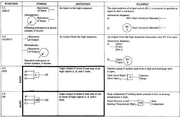
FIG. 2a Logic diagram symbology.
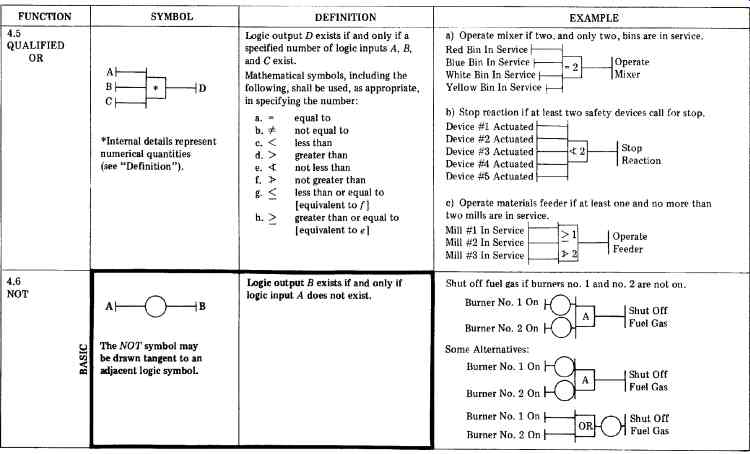
FIG. 2b Logic diagram symbology.
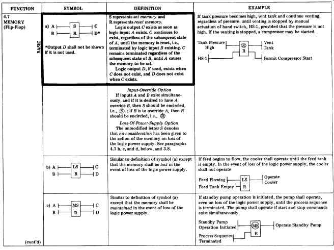
FIG. 2c Logic diagram symbology.
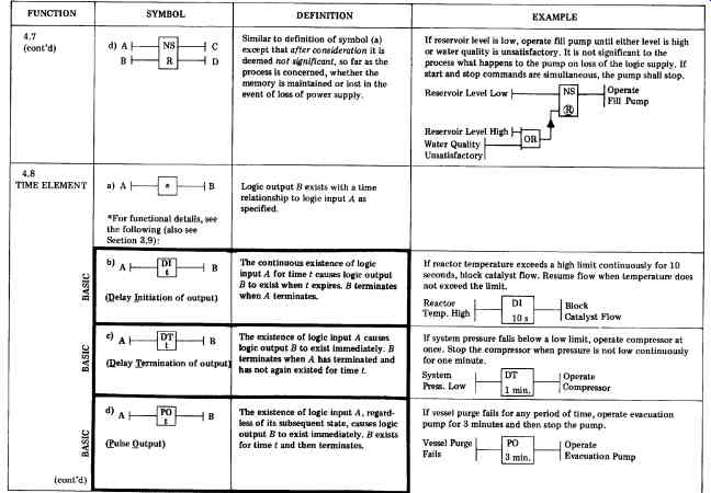
FIG. 2d Logic diagram symbology.
An example of a logic diagram is shown in FIG. 3. In typical logic diagrams, the inputs are shown on the left-hand side of the drawings and the outputs on the right-hand side. A master logic diagram or legend sheet is required to explain line identifications and describe all the symbols used to create such diagrams.
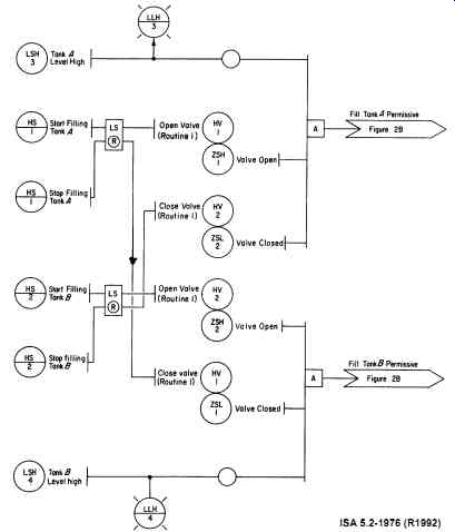
FIG. 3 Typical logic diagram.
Process Data Sheets
Process data sheets contain the process data related to a particular instrument. They form the base upon which the process information is relayed from the process engineer to the instrument engineer. Specification sheets are then prepared and instruments selected. FIG. 4a is an example of a process data sheet showing the operating parameters and is taken from ISA TR20.00.01-2001, Specification Forms for Process Measurement and Control Instruments.
The simplified process data sheet shown in FIG. 4b will in most cases have additional columns focusing on fluid viscosity, conductivity, vapor pressure, and the like.
Typically, process data sheets are generated after the P&IDs are prepared and the control equipment defined. It is of prime importance that these process data sheets be completed before instrument specification sheets are prepared. Verbal communications and assumptions made by the person completing the instrument specification sheets can be a source of misunderstanding, trouble, and expensive errors.
[coming soon] FIG. 4a Process data sheet (detailed format).
[coming soon] FIG. 4b Process data sheet (table format).
Instrument Index
The instrument index document is an index of all items of instrumentation on a specific project or for a particular plant. Its main purpose is to act as a cross-reference between all items of instrumentation and their related documents (see FIG. 5). The instrument index is commonly generated and maintained on personal computers using a database manager, a spread sheet, or a word processing file. This computerized approach makes it easier to update the instrument index and is strongly recommended for facilities that have a large number of instrumentation devices.
[coming soon] FIG. 5 Content of a typical instrument index.
The instrument index is normally in tabular form. Typically, the following items are representative of the content listed on an instrument index:
1. Tag Number-This is a unique instrument identification (e.g., "TT-238") shown on the P&ID, and its allocation, in most cases, is based on ISA-5.1-1984 (R1992) (refer to section 2 of this handbook for further information).
2. Description-The function/purpose of the instrument is described here (e.g., cooling tower inlet temperature).
3. P&ID-The process and instrument diagram (P&ID) that contains that tag number is referenced here.
4. Line/Equip.-The number of the line or equipment onto which the instrument is mounted is identified. This facilitates the search for an instrument on a particular P&ID and also simplifies the search for piping, mechanical, and vessel drawings.
5. Spec. Sheet-The specification sheet number for a particular device is listed.
6. Manufacturer's Drawings-Vendor-supplied drawings and manuals are cross-referenced here to facilitate future retrieval. In many cases, these drawings and manuals are numbered to conform to plant-produced documents that follow an established numbering sys tem.
7. Loop Drawing-The wiring or tubing of the instrument is shown and referenced on this drawing.
8. Interlock Diagram-The interlock diagram in which an instrument is present is identified here.
9. Location Drawings-The location of the instrument on a line (or vessel) is referenced for future use at installation time or later on during maintenance. This drawing could also be a piping drawing (see Section 15 on installation).
10. Notes-Any notes or remarks related to instruments are listed (e.g., "Instr. supplied with cooling tower").
Some additional data that can be found on an instrument index are the following:
• Other drawings that relate to a specific instrument (e.g., typical installation details, other electrical drawings)
• Equipment supplier and model number
• Purchase order number, etc.
Instrument Specification Sheets
The purpose of the instrument specification sheets is to list the pertinent details of a particular instrument (i.e., a record for the functionality and description of that instrument). It is intended for use by engineers and vendors as well as by installation and maintenance personnel. Specification sheets provide uniformity in content, form, and terminology, which, in turn, saves time and minimizes errors for designers and users of such data.
When preparing instrument specification sheets, refer to ISA TR20.00.01 for existing forms, with instructions. FIG. 6 shows a typical instrument specification sheet using one such ISA standard form. Some corporations develop their own set of specification sheet forms to meet their specific needs. Remember that a process data sheet must exist for every instrument that is in contact with the process.
[coming soon] FIG. 6 Instrument specification sheet.
The specification sheets must show compliance with the electrical code in effect at the site.
This equipment must be approved and bear the approval label (e.g., UL, FM, or CSA), or, at a minimum, it must have the approval of the electric power authority in the region in which the equipment is installed. Non-approved equipment should not be installed, or liability, legal, and insurance problems may arise. For control equipment located in hazardous locations, the ISA has published a series of standards on this subject. Intrinsic safety (IS) through the use of barriers is the preferred method of protection in hazardous environments for many plants. However, other plants still prefer explosion-proof or purged enclosures. In any case, compliance with the code requirements is a must.
Loop Diagrams
The loop diagrams show the detailed arrangement of instrumentation components in a loop.
They are used during design, construction, startup, and maintenance. All devices, pneumatic and electronic, that carry the same loop number are generally shown on the same loop diagram.
This makes the loop diagram an ideal tool for troubleshooting. At a minimum, the loop diagram will show the interconnection of the devices, their locations, their power sources, and their control actions.
In general, a loop diagram should be prepared for each instrument loop that contains more than a single instrument. Normally, the only instruments that do not require loop diagrams are inter lock systems (which are shown on the interlock diagrams) and local devices such as gages, regulators, and relief valves. For these local devices, an entry in the instrument index should be sufficient. A master drawing (or legend sheet) should be generated to explain all the symbols used in loop diagrams.
The content and format of the loop diagram should conform to a plant standard or, if one doesn't exist, to ISA-5.4-1991, Instrument Loop Diagrams. FIG. 7 and 8 are reprints from this standard. ISA-5.4-1991 was published to provide guidelines for preparing and under standing loop diagrams and to identify optional information that may be shown on them. This ISA standard closely relates to ISA-5.1-1984 (R1992). Some organizations keep track of the instrument loops by using tables generated through a database manager instead of loop drawings. This practice is more suited to modern distributed control systems than to analog instrumentation. While it reduces the number of drawings generated, it may not be acceptable to the installing contractor or to maintenance personnel. Many engineers, contractors, and maintenance personnel still prefer the "old-fashioned" loop diagrams over tables.
The following points are considered as good engineering practice when preparing loop diagrams:
• The electrical and pneumatic details of a single loop are not separated; rather, they are shown on the same loop diagram.
• Each instrument signal must be grounded at one point only, preferably in the control room.
• All cable shields must be continuous (connected across junction boxes, etc.) and care must be taken to adequately insulate the shield over its entire length so as to maintain the one point connection (see the section on grounding in Section 1 of this handbook for further information).
Loop diagrams are generally the source of the wire numbers for all analog devices and for discrete devices that are not shown on any interlock diagram. The same rules apply for creating wire numbers on loop diagrams as for interlock diagrams. The only difference is that since there are no rung numbers, loop numbers are used. Each wire in the plant should have a unique number. The wire number is typically composed of a loop number followed by a dash and a sequential number starting with 1.
Loop diagrams were originally developed based on the concept of physical connections between individual devices, each performing a specific function. Modern control systems tend to have a measurement, a final control element, and a computer-based control system that per forms most of the monitoring and control functions. The representation on the loop diagram in this case would not generally show the functions of the monitoring and control function. On the other hand, to show all this detail on the P&ID may, in some cases, overload the P&ID.
Some corporations have adapted PMC 22.1, the function diagramming standard of the former SAMA (Scientific Apparatus Makers Association) organization, or have developed their own symbology to represent the control function. The functions performed in software may be shown on dedicated drawings or even described in the control scope definition. The final decision regarding where the functionality of the software should be shown depends on the complexity of the loop and the corporate culture. If separate drawings are used to describe the monitoring and control functions, they could be part of the control system definition document, with a master drawing generated to describe the symbology used.
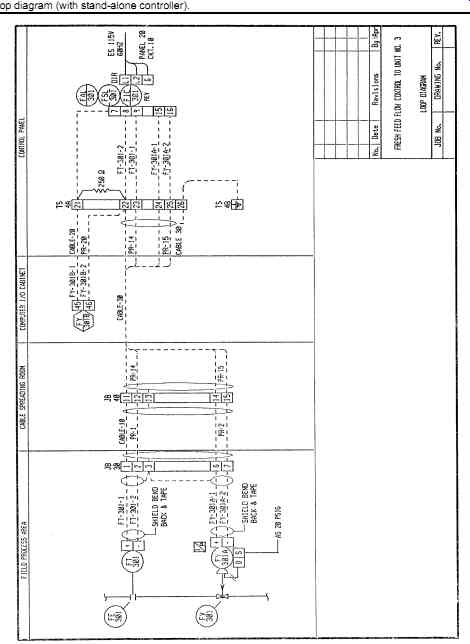
FIG. 7 Loop diagram (with stand-alone controller).
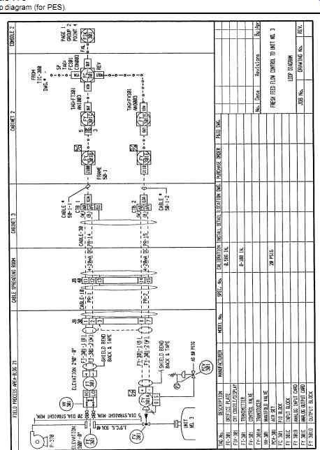
FIG. 8 Loop diagram (for PES).
Interlock Diagrams
The interlock diagram (also known as "electrical control schematic" or "electrical wiring diagram") shows the detailed wiring arrangement for discrete (on-off) control (see FIG. 9).
Generally, the only control circuits that do not require interlock diagrams are analog loops, which are shown on loop diagrams. With the extensive use of programmable electronic systems for performing logic functions, the use of the interlock diagram is not as widespread as it was years ago. However, some applications still require such drawings, such as hardwired safety trips and motor controls. A good quality interlock diagram will always be in agreement with the corresponding logic diagrams.
All devices on interlock diagrams will generally have a tag number, location, and service description. In addition, all rungs on these diagrams are numbered sequentially. The numbers start from the top of the diagram and increase, going down the ladder and continuing through all the diagrams created for the project. In North America, the symbols used are based on IEEE Standard 315A-1986. Each rung on a project should have a unique number, and each wire in a plant should have a unique number. These diagrams are the source of wire numbers for discrete control, which begin with the rung number, followed by a dash and a sequential number on the rung, starting with 1. Typically, the wire number does not change after it goes through a terminal block unless it is a fused terminal block. It changes only after a switching device or load, that is, fuse, switch, or coil. A master drawing (or legend sheet) should be generated to explain all the symbols used.
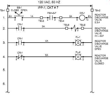
FIG. 9 Typical interlock diagram.
Manual for Programmable Electronic Systems
The primary purpose of a programmable electronic system (PES) manual is to serve as a reference for the ongoing support and maintenance of the PES system after final commissioning and startup have taken place. This section will provide a framework and checklist from which a plant can produce the manual for (PES), such as PLCs and PCs. The exact layout of the manual will depend on the plant's needs, the level of training, the corporate culture, and the system selected. The information contained in such manual spans the hardware and software, including the input/output modules and the operator interface and/or supervisory computer. Typically, the manual may be broken down into the following sections, with each showing its contents:
• Overview and General Information
• Manual layout description and index
• Brief description of the PES
• PES design philosophy (such as failure modes, etc.)
• PES modification history
• System Startup Procedure
• Overview, in which critical process and personal safety information must be high lighted
• Specific startup instructions
• List of control set points and parameters
• PES Communications
• Data communication overview (include block diagram)
• Network information
• Cabling and connection information (pinouts, jumpering, shielding requirements, dip switch settings)
• List of available reference manuals
• Input and Output, including Programmable Controllers (PLCs) and Standalone Controllers
• Input and output cross-reference list
• Program structure overview
• Annotated program file listings
• Device memory allocation listing
• Program backup procedure
• General information; software versions, dip switch setting, jumper configurations, electrostatic damage prevention, etc.
• List of available reference manuals
• Operator Interface
• System screen layout and listing
• Operator keyboard functional description, complete with function key index, if applicable
• Full database listing, including link structure, if any
• Input-output scanner(s) configuration and listings
• Backup procedure
• Host computer general information (operating system and version, directory structure, description of hardware components, dip switch settings, jumper con figurations, electrostatic damage prevention, etc.)
• List of available reference manuals
• Reference documents
• Index
• Equipment manufacturer's product data sheets for all components
• Miscellaneous
• Index
• List of support persons, including manufacturer's "hot line" support
• System backup disk(s).
The writing style of this manual should be clear and concise. Descriptive sections should avoid excessive technical jargon, and acronyms should have their meaning spelled out on first occurrence (e.g., RAM = random access memory). In addition, the group that will be responsible for PES support and maintenance at the plant should be consulted regarding the number of manual sets required. The manual(s) should be updated to incorporate any system modifications that take place and should include a modification history that documents the nature of the modification, the date of changes, and the name of the person responsible for the change. The content of such a manual must comply with the regulations in effect at the site and is particularly applicable to critical loops.
PLC Program Documentation
An important part of any documentation package is the PLC program (where PLCs are used).
With the proliferation of PLCs, the format in which the program (generally ladder logic, but also any other IEC-approved language) is described should be agreed upon. Without such a description, the review and editing, especially on large programs, becomes an impossible task.
PLC program documentation may, for example, conform to the following requirements:
• The programming should be written in the format requested by the plant and comply with the existing plant software.
• The individual I/O description should show:
• the tag number (e.g., LSH-123);
• a description (e.g., TANK 17);
• any notes (e.g., instrument location or PLC I/O address, etc.);
• in addition, for ladder logic, all outputs/inputs should be cross-referenced to the rung(s) to which they connect.
• Each section of the program should be clearly explained. The ability to display or not display the rung descriptions should be available to speed up the programming and trouble shooting activities.
• The PLC program may be simulated on a personal computer (PC) prior to commissioning, and the software used should have the ability to compare two programs and flag differences. This is a useful feature when comparing the latest running program with the master or "approved" program.
In situations where the program is developed and implemented by outside contracting firms, the owner may want to include a sample PLC program. However, even in spite of such a sample program, it should be kept in mind that different programmers do not have exactly the same approach and format style, even while using the same example as a format. So the owner should coordinate and continuously review all programming during program development to ensure quality.