AMAZON multi-meters discounts AMAZON oscilloscope discounts
Analyzers are used to measure analytical values. The most frequently used analyzers in the process industries are pH and conductivity analyzers. Of all the typical measurements, such as flow, level, pressure, and so on, process analysis tends to be the most difficult, the least under stood, the most troublesome, the most expensive, and the most difficult to maintain. It’s there fore imperative that the user handles process analysis carefully and gives it the time (and money) required for a successful installation. Laboratory and portable analyzers won’t be discussed in this guide.
When selecting an analyzer, the user should preferably choose a time-proven off-the-shelf device. Custom-built analyzers tend to have debugging problems and lead to difficult and expensive maintenance.
The cost of implementing an analyzer system is typically much higher than the cost of the analyzer itself. An analyzer system may include a sample probe, a sample line, a shelter, sample disposal equipment, and calibration gases. In addition, ongoing maintenance costs includes the cost of maintenance personnel and their training, the replacement of calibration gases, the cost of the calibrating equipment, and utilities.
Location:
When deciding upon the location of an analyzer, there are two possibilities: extractive and in situ. Some analyzers are mounted remotely from the sample point; these are known as "extractive" analyzers. This approach is implemented when the process conditions are severe, when the sample point is practically inaccessible, or when the analyzer's capabilities require it (e.g., it’s not built for an industrial environment). Extractive-type analyzer systems draw a sample from a remote location through a sample line to the analyzer. Such systems are also used where many analyzers are sampling a single process, and the sample can therefore be shared by more than one analyzer. Extractive systems typically require a probe, a sample line (sometimes heat traced), a pump, filters, sample line flushing, a means for calibration, and other miscellaneous equipment. The cost of extractive systems is much higher than in-situ systems. They also require more maintenance.
When extractive analyzer systems are implemented, they are typically assembled in a con trolled environment by a specialized vendor in a specialized shop. This provides a better-quality final product. These preassembled systems are normally tested before being shipped to site, minimizing startup problems.
Analyzers that are mounted in line are referred to as "in-situ" analyzers. With in-situ types, the instrument analyzing the sample is at the process and does not have to extract a sample. This eliminates all the sampling problems, and measurement can be achieved without the time delay created by sample lines.
Tagging:
Tagging is required to identify all parts of an analyzer system, including all components of the sample system, valves, switches, circuit breakers, field connection points, and gas cylinder connection points. The tagging information is typically identified on nameplates that are attached with stainless steel screws or wire (refer to Section 2 for further details on the tagging of instruments). Attaching the nameplates with adhesive is an acceptable alternative for temperature-controlled environments.
Implementation:
It’s important that the user prepares a technical specification that covers every component of an analyzer system. This specification should include the system's design, fabrication, supply, installation, and startup. It’s generally expected that the system vendor will furnish all the material needed for a complete and workable system.
The user needs to define the following in the technical specification to ensure a good match between the supplied analyzer system and the plant requirements:
• A description of the process and a tag number for the analyzer(s)
• The components to be measured, with the range of measurement and the required accuracy
• The concentration of all other components and contaminants in the sample stream (even if only traces), with their expected range
• The conditions of the process, that is, the minimum, normal, and maximum range for temperature and pressure
• The materials of construction in contact with the sample that can (or cannot) be used
• The physical state of the sample, that is, liquid, gas, and so on.
• The hazards of the sample
• The electrical area classification
• The available power and utilities (such as instrument air)
• The environmental conditions (ambient temperature, corrosive environment, dusts, vibration/shock, etc.)
• The type of measurement, that is, continuous or intermittent-and at what interval?
• The analyzer response time versus the time required by the process
• The warm-up time for the system following a restart, and the frequency that the analyzer is expected to shut down
• The requirements for analyzer output signal (e.g., 4-20 mA, RS232C, etc.) and display (analog or digital? local and/or remote?)
• The need for a sample probe and sample line
• The required analyzer(s)
• The enclosure that will contain the sampling systems, the analyzers, the exhaust system; will it consist of either a climate-controlled walk-in enclosure (known as the shelter) or a cabinet?
• The calibration system (such as gas cylinders with regulators)
• When required, a strip-chart recorder or connection to a data collection system to continuously record the analyzed value(s) For most analyzer applications, it’s good practice for the user to discuss the requirements and implementation with one or more reputable suppliers. Both the plant and vendor must work closely to ensure a successful implementation.
The plant's responsibilities typically encompass the following:
• Specify the process data and system requirements by preparing the technical specification.
• Review all vendor designs. It should be noted here that unless plant personnel are very experienced in the application of analyzer systems, the system vendor must be made responsible for the design, implementation, and overall suitability of all components for performing the required analysis.
• Witness the testing at the system vendor's facilities.
• Install the enclosure and sample line. The system vendor may connect both ends of the sample line.
• Connect to the structure's grounding.
• Install and terminate all power and signal cables.
• Install and connect all utility piping The system vendor's responsibilities typically include the following:
• Provide a qualified project engineer who will work closely with the plant engineer for the duration of the project. The system vendor may be required to submit the project engineer's résumé for the plant's approval at the bidding stage. A relationship with the vendor's designated engineer should be maintained until the project's completion.
• Prepare and submit a schedule showing complete detailed activities, starting with the verification of the analyzer specifications and continuing until the field checkout and final acceptance of the system. This schedule should be updated regularly, with the frequency depending on the project's requirements.
• Develop complete installation and electrical drawings showing all material being used, the power source required, wire sizes, terminal designations, wiring by the plant, circuit breaker values, and so on. Drawings should be submitted for the client's review.
• Prepare a bill of material for all equipment, using the names and model numbers of the original manufacturers.
• Finalize the design and submit final drawings.
• Specify and purchase all auxiliary equipment, as applicable, for a complete, fully functional analyzer system. This includes tube fittings, terminal blocks, and the like.
• Expedite all purchases.
• Construct the system.
• Notify the plant in writing when the system is fully operational and ready for testing at the vendor's facility.
• Provide the initial set of cylinders of calibration and consumable gases; they are to remain the property of the plant.
• Conduct a thorough system test, with plant personnel in attendance.
• Arrange and prepare all equipment for shipment.
• Prepare and submit final documentation.
• Make available qualified personnel to supervise the field installation.
• Install the sample probe and connect it to the sample line.
• Make all connections from cylinders to the cabinet and connect the sampling line to the cabinet.
• Prior to startup, do a complete mechanical, loop, and electrical check (with sample line in operation).
• Start up all analyzers and sampling trains.
• Calibrate all instruments and provide the final calibration results to the plant.
• Conduct operation and maintenance training classes at the plant.
• Perform system checkout and startup, with plant personnel in attendance.
• For new plants, provide a qualified person to return to the plant to assist during process startup.
In most applications, the bidders are required to supply, as a minimum, three references that have similar process applications (with a contact name and phone number) as well as a service support plan with expected response time and personnel availability. The plant's personnel should contact these references to confirm the vendor's capability.
Safety:
It’s imperative that the measurement and control system be installed safely. Therefore, the following steps should be taken:
• Insulate all high-temperature equipment (i.e., sample lines, heat-traced system components, electrical connections, etc.) to protect personnel. Hot lines or analyzers, which can not be insulated, must have guards placed around them to prevent possible injury.
• Provide a means to flush the sample system components for repair or replacement. Note that there may be no sewer, and the only means of disposal may be a suitable container and/or pump-out system.
• Atmospheric vent lines should be adequately sloped to the vent bulkhead to avoid trapping condensate. This bulkhead should have a drain at its lowest point.
• Design the sampling system to minimize the volume of hazardous gases (toxic or flammable) entering the analyzer enclosure. Suitable flow restrictions should be provided between the analyzer enclosure and the supply source of hazardous gases. This includes the supply of calibration gases.
• Use relief valves (or bursting disks) in cases where the failure of a part could cause an analyzer or sample system component to over pressurize.
Code Compliance
The implemented system, including all design, equipment, and installation, must comply with the statutory and regulatory requirements that are in effect at the site. These requirements may include, for example, the latest edition of the National Electrical Code (NEC), Canadian Safety Association (CSA), Environmental Protection Agency (EPA), National Fire Protection Association (NFPA), and the latest edition of ISA's Standards Library for Automation and Control. Typically, it’s the vendor's responsibility to ensure that the supplied system meets such requirements. In addition, the installation must also meet the specific requirements of the local authorities. These may include analyzer performance (accuracy, drift, response time, etc.).
All electrically operated instruments, or the electrical components of any instrument, should be approved and bear the approval label (UL, FM, CSA, etc.). The plant's maintenance personnel should remember that any modifications they make to approved equipment may void that approval.
Selection
When selecting an analyzer, the user must assess the effects of power loss and power restart as well as the required startup time. Startup time is defined as the time interval between the moment when the system is switched on (power and sample) and the analyzer(s) generates an output that indicates the analyzed value(s). Switching the system on includes switching on other utilities (such as instrument air) and bringing the sample-handling system and all system components to a working condition within the stated limits of performance. The vendor is expected to advise what the startup time is, and the plant should check that this time conforms with the process requirements.
The analyzer system typically provides output signals to the plant control system to indicate analytical values, to signal alarms, or to initiate the shutdown of the process. When the link to the plant control system is digital, the plant user must ensure that the communication protocol is an off-the-shelf item. Custom software that has never been used before tends to take longer to develop than originally planned and tends to have a longer than anticipated debugging period.
Analyzer outputs are sometimes sent to a chart recorder to conform to environmental regulations that require a continuous and direct link to the analyzer(s). Hardwired alarm contacts for the analyzer system, identifying component failure, should be tied into a common trouble alarm. This common alarm might activate a red beacon located on top of the enclosure and provide a contact that is to be connected to the plant's control system (see the subsection "system Alarm" in the section titled "Enclosures" later in this Section ). Where the user needs to measure stack flow many methods are available (see Section 4 on flow measurement). In all cases, the location of the measuring device should be immune to the effects of pulsating or cyclonic flow. Typically, one of the following three methods is used:
• Differential pressure. Frequent blowback may be required when using this method to pre vent probe plugging. An averaging pitot tube is commonly used. If a single pitot tube is recommended, the bidders and the plant must assess its advantages.
• Thermal. When using this method, the system designer should consider the effects of particulate buildup on the sensors, water droplets causing a bias due to evaporation, and acid droplets corroding the probe.
• Ultrasonic. In environments where transducers are exposed to the process, buildup on sensors must be avoided. It may be necessary to use blowers to keep the transducers clean.
There are many analyzers on the market today. Different analyzers are capable of measuring the same component. When selecting an analyzer the user must evaluate such parameters as the following:
• The analyzer's individual characteristics
• Its cross sensitivity with other components in the stream or sample
• Its range, accuracy, and speed of response
• Its cost
• The plant's experience with a particular analyzer
• The plant's working relationship with a particular supplier and that supplier's capabilities Most analyzers can be divided into family type. The most common ones are: physical property, electrochemical, spectro-photometric, and composition.
Physical property analyzers use a measurement technique that provides data correlated to a laboratory measurement. These analyzers include capillary tube, rotating disk, thermal conductivity, and vibrating U-tube.
Electrochemical analyzers typically use electrodes to measure ions, such as pH-measuring hydrogen ions. These analyzers include the following types: amperometric, catalytic, conductivity, polarographic, and zirconia oxide.
Spectrophotometric analyzers are based on the phenomenon whereby molecules in a sample stream absorb light at specific frequencies. These analyzers include the following types:
chemiluminescence; infrared absorption, including Fourier transform infrared (FTIR) and non dispersive infrared (NDIR); and ultraviolet (UV).
Composition analyzers are based on the separation and measurement of components in a process stream. These analyzers include flame ionization analyzers, gas chromatographs, and mass spectrometers.
Documentation
Plants need vendor-supplied technical manuals. A minimum of three copies is typically required, one for engineering, one for maintenance, and one to be left at the analyzer enclosure.
The manual's content should cover the technical information for all analyzers, accessories, enclosures, and sampling system, namely:
• A drawing showing the complete analysis system, with a flow schematic of the sample systems and analyzers and a list of all material components (especially the ones that come into contact with the sample fluid)
• Specification sheets and cut sheets for the analyzer(s), the sample system hardware, and all other associated hardware, as well as their limit conditions of operation, storage, and transport
• Installation, operation, and maintenance instructions for each piece of equipment, including calibration and troubleshooting procedures
• Startup, operating, and shutdown instructions
• A description of the logic required to blow back the sample system and calibrate the analyzer
• All wiring schematics
• Factory sample calibration data reports
• A parts list(s) and recommended spare parts list(s), including prices and lead times Sampling Systems
Sampling systems provide a representative sample from the process to the analyzer(s). They are an essential part of any extractive-type analyzer and typically the most troublesome part when they are implemented improperly. An integral part of the sampling system is the instrumentation necessary to ensure the sampling system's proper functioning or to facilitate maintenance work.
The sampling system extracts a sample, transports it to the analyzer(s), conditions it to the analyzer's capabilities, and finally exhausts the stream to a safe disposal point. A sampling system should not alter the sample, should be leak free, and quite often should maintain the sample within a set temperature and pressure range. Most sampling systems also can do zero and span calibrations of the analyzer they are connected to. The materials used in the sampling system must not react with the sample, absorb components of the sample, or transfer contaminants through osmosis. The sampling system must avoid polymerizing, stratifying, or contaminating the sample.
Depending on the sample to be analyzed, the sampling system must sometimes reduce (or increase) the temperature or pressure of the sample, restrict and/or filter flow, or wash and/or dry the sample. Sometimes, vapor samples are heated to prevent condensation. In other cases, liquid samples are vaporized. A sampling system may remove or alter material that may plug or corrode the analyzer, but it should not alter the variable component to be measured. The composition and the physical state of the fluid in the sample line can only be allowed to change in a predictable way.
To provide good system response, sampling lines must be kept at a minimum length and pro vide a sufficient flow rate to each analyzer. The volume of the sample system should be kept at a minimum, and the sample flow velocity should be kept high, typically, about 5 to 10 ft/sec (1.5 to 3.5 m/sec). Where possible, the sample system should be provided with the necessary flow, temperature, and pressure indicators to determine whether the sample conditions required by the analyzer system are met. The sampling system must not create an unsafe or flammable condition.
Any sample line that enters an enclosure should be fitted with a fixed restrictor mounted out side the enclosure. The line should be sized to limit the full release flow from a fractured sample line in the enclosure to a calculated safe level matched to the house ventilation flow.
Adjustable valves should not normally be used in place of fixed restrictors since they can be easily modified. Lines that carry hazardous fluid should have automatic isolation valves to shut off the sample line in case the enclosure's ventilation fails.
If required, dilution extractive systems can be used. These systems dilute the sample with an inert fluid at a known ratio. This approach reduces problems with sample handling; however, it increases the complexity of the sampling system and reduces the sample sensitivity (since it’s diluted). These systems should be designed to maintain a constant flow, temperature, and pres sure for the dilution fluid.
The plant may have to employ automatic switching to share one sample among many analyzers or to have different samples analyzed by one device. Switching is typically accomplished by using solenoid valves. However, these valves may leak. If this is unacceptable, the plant will need to use a double-block-and-bleed valve arrangement (see FIG. 1).
IN BLOCK VALVE 1 BLOCK VALVE 2 OUT BLEED VALVE
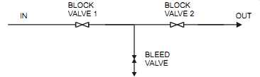
FIG. 1 Double-block-and-bleed valve arrangement
In most applications, a logic is required in order to blowback and calibrate the system. This is generally supplied by the analyzer system vendor as part of the total analyzer package. In most cases, clean and dry instrument air, typically regulated at a preset pressure, is required for blowback. If instrument air is not available, then the plant may have to use high-quality bottled air or a compressor/dryer combination.
To permit effective isolation, the plant may need to install suitable block valves immediately downstream of the sample take-off point, at the inlet and outlet of the analyzer, and in the sample return line. In addition, the application may require a sample connection for lab checking just upstream of the analyzer. This makes possible direct correlation between the analyzer out put and the lab results (an effective and rapid method of analyzer validation and troubleshooting).
Sample Point
The sample point location should be selected so as to provide a sample that is clean, measurable, and representative. Good access for maintenance personnel is a must, and an access plat form may have to be provided where needed.
The location for a sample point should be selected so as to prevent plugging and to reduce entrainment in the form of liquid droplets for gaseous streams or gas bubbles in liquid streams.
The plant may have to use traps, filters, separators, and even scrubbers to remove harmful or signal-disruptive entrained contaminants. The sample point internal diameter should be large enough to prevent blockage.
The sample point should be immune from the effects of flow stratification. Cross-sectional multi-point extraction, vanes, or baffles may be required. The sample point must be representative of the cross-sectional area being measured, and its location should avoid multi-phase streams.
Where a Continuous Emission Monitoring System (CEMS) for a stack is required, the sample point location must conform with local regulations regarding the number of stack diameters upstream and downstream of a sample point. Typically, the sample point is located eight diameters after the inlet breach to ensure good mixing and two diameters below the stack exit to avoid atmospheric contamination.
Sample Probe
Where it’s necessary to use a sample probe for the sample stream, a full-bore block valve is generally required for isolation. The probe must be made of a material that won’t corrode, be long enough to obtain an accurate sample, be located so as to minimize fouling, and be accessible (i.e., an access platform may be required). It’s important to assess whether doors will be needed to allow the insertion, maintenance, and retraction of probes. Most systems are designed to make it possible to calibrate the whole system by introducing the calibration sample at the sample extraction point. This permits the system as a whole to be calibrated.
Particulate matter may cause probes to plug. So, for horizontal installations, the probe should be pointing slightly downward so that condensation can be returned to the process and blow back will be more efficient (see FIG. 2). Blowback is typically used to clean the probe and sample filter.
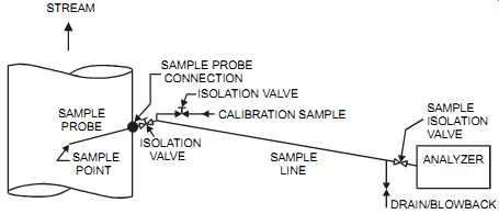
FIG. 2 Sloped probe with blowback connection. STREAM SAMPLE; PROBE SAMPLE; POINT
SAMPLE PROBE; CONNECTION ISOLATION VALVE CALIBRATION SAMPLE ISOLATION; VALVE
SAMPLE; LINE SAMPLE ISOLATION VALVE ANALYZER DRAIN/BLOWBACK
In negative pressure systems, leaks will dilute the sample. Probes and the sampling line must be carefully tested to ensure that that are no leaks in the system. Also, very high temperature applications may require the use of water-cooled probes to cool the sample and provide longer probe life.
Sample Line:
To avoid lags, the sample line should be as short as possible so the probe is as close as possible to the analyzer. A distance of up to 100 ft. (30 m) from the analyzer is considered acceptable in most applications. If the process fluid is at a high temperature, it must be cooled. A length of plain tubing may provide adequate cooling-however, the plant must be sure this is the case.
The sampling line is typically made of ¼? to ½? stainless steel tube, depending on the sample.
Since most process streams contain contaminants, the plant should avoid loops or low areas that will trap liquids or particles. Proper support should also be provided where lines enter an enclosure to minimize mechanical stresses on the line and fittings.
Depending on the sample components and on the surrounding climate, the sample line may be heated (and insulated) or unheated. If it’s unheated it may be insulated or left bare. Line heating can be performed with steam or electricity. In either case, the plant must assess the con trolled temperature range of the heating medium against the sample temperature requirements.
Where steam-heated lines are used, line accessories such as traps and temperature controls are required. Steam heating is commonly used where steam is cheaply available or in electrically hazardous areas where electrical sparks may cause an explosion. However, steam heating may be expensive to maintain. In addition, steam leaks could be dangerous to personnel and to sensitive analyzer equipment. The plant should properly insulate the tubing transitions between heated lines and non-heated fittings to minimize heat losses to the surroundings.
Integrally heat-traced-and-insulated sample lines are typically pre-cut at the factory with extra length to allow for errors in measurement. In most cases, the extra length should not be looped since looping may result in line blockage or liquid pockets-both conditions will greatly affect the performance of the analyzer(s). In extreme cases with electric-traced sample lines, looping the sample line on itself can cause the insulation on the sample line to ignite, destroying the heat-traced line and creating a hazard. The plant should install excess length with a continuous downward slope.
Line Accessories:
The number of fittings and joints in the sample system must be minimized to avoid leakage points. In addition, the plant should locate a sample isolation block valve outside the analyzer enclosure to allow safe isolation. A catch pot may be required to retain any moisture that may have dropped out during the sample transfer of gaseous samples.
Where pressure boosting is required, plants commonly use leak-free pumps. Note that doubling the pressure doubles the amount of gas in the line. Sample pumps, where required, are typically of the diaphragm type, with all the components that contact the fluid being made of a material that won’t react with the fluid being transferred. Pump head and bearings must be capable of operating continuously twenty-four hours per day.
Where the plant requires a pressure reduction of the process fluid, a pressure control valve (PCV) is commonly located at the sample point to keep the high pressure at the process and reduce the dew point. Sometimes, to dry the sample even further, the plant removes the water before the gas pressure is reduced. The plant must assess the effect of removing water on the sample concentration of the gas being analyzed. A safety pressure-relief valve (or bursting disk) may be required downstream of the PCV to guard against sample pressure buildup in the event the pressure regulator fails.
Filtration is generally required on all sampling lines. Filters must be suitable for the physical and chemical composition of the sample. The filter's porosity must be small enough to protect the analyzer yet not too small, otherwise the filter will plug rapidly. Filters must be easy to maintain and replace. Some filters may be of the self-cleaning type (tangential swirl).
Sample Disposal:
Once analyzed, the sample should be routed to an acceptable and secure location, preferably back to the process (see FIG. 3). The plant must dispose of safe samples in conformance with all local codes and regulations. Typically, plants assess the following three parameters before deciding about sample disposal: discharge pressure and temperature, maximum concentration of hazardous components, and the flow rate of exhaust stream.
PUMP SHUT DOWN; PUMP START/ STOP BACK TO PROCESS PUMP VENT OPTIONAL FLAME ARRESTER LAHH LSHH LSHL; FROM ANALYZER
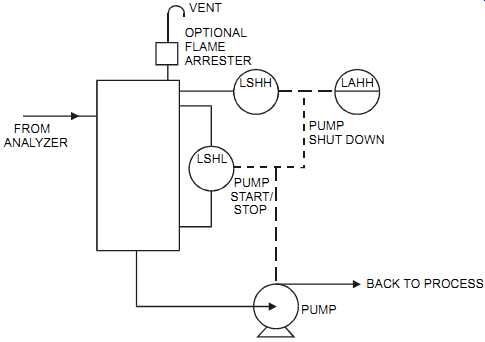
FIG. 3 Liquid sample recovery and disposal.
The plant must ensure the proper disposal of process samples, the atmospheric vent, the stack vent, and the sample recovery system. The analyzers must be vented in most applications, and it’s recommended that the analyzers be vented where there is a minimum of turbulence and where the pressure is constant. Variations in analyzer back pressure will cause significant errors in measurement, and therefore, a back-pressure regulator is sometimes required. A good regulator will maintain a back pressure within +/- 0.5" of water column (WC).
All piping should be routed and designed to prevent condensation from accumulating in line pockets as well as to prevent rain and debris from entering the sample vents. All drains and vents should be installed at a suitable incline toward the discharge.
Enclosures
Extractive analyzers are commonly housed inside enclosures. These enclosures protect the sensitive analyzers and their accessories and also provide a clean and sheltered environment so that the equipment can operate more efficiently and be maintained in all-weather conditions.
These enclosures can be wall-mounted cabinets, floor-mounted panels, or self-contained walk in shelters. In most cases, they are shop-fabricated before they are shipped to the site. Walk-in shelters are shipped on skids. The analyzer enclosure should allow the analyzer to be located safely in the plant, as close as possible to its sample point, and must conform to the electrical code in effect at the site. Additional information on enclosures is provided in Section 12 of this guide.
If a plant locates analyzer enclosures in a hazardous area, the inside of the enclosure is commonly designed as a safe area. In the safe area, the plant may have to install an internally located detector(s) with annunciation to a central area, such as a control room. If ventilation stops or if the detector(s) alarms, all electrical power to the analyzer enclosure is cut and all inflow of flammable samples is halted. In addition, analyzers that handle flammable samples are air purged, and failure of the air purge should cause a power interruption. Purging requirements vary with the purge classification, which should be implemented according to the applicable code (also see ISA-RP12.4-1996, Pressurized Enclosures).
All sample lines that carry hazardous fluids and are fitted with flow restrictors should have automatic isolation valves (spring-to-close) located outside the enclosure. These valves shut off the sample lines in the event of purging failure. If such valves are dependent on the enclosure electrical supply, then when the purging fails the resulting electrical supply shutdown to the enclosure will automatically isolate the sample. The startup delay setting should be in compliance with the applicable code (which is typically calculated for ten complete internal air changes of the enclosure).
Construction
The enclosure is generally made of a weather-proof construction and must meet the electrical area classification of its intended location, the ambient temperature and humidity fluctuations, and any other environmental requirements such as earthquakes, rainfall, and wind velocity. In addition, the enclosure should have adequate strength and sealing to withstand internal pressurization to 2" WC (50 mmwc). The enclosure may have to be insulated to reduce heat loss and eliminate condensation without hindering the installation of analyzers and their associated piping and wiring, or it may have to be large enough to dissipate heat buildup.
The enclosure's dimensions depend on the number and type of analyzers and associated equipment as well as the need to provide easy access. At the early stages of implementation, bidders should include preliminary enclosure dimensions in the initial proposal that they submit to the plant engineer for review. If possible, the system should be assembled so that any one analyzer can be removed or serviced without interrupting the operation of any other analyzer in the enclosure.
Some process equipment creates vibration. Such vibration must be properly isolated from the enclosure. Also, the plant must take proper precautions to eliminate the transfer of electrical noise to the analyzer from components such as pumps and solenoid valves.
Walk-in Shelters
Walk-in shelters are used where a cabinet (or panel) is not the preferred enclosure. This occurs when either the cabinet is not large enough or when opening a cabinet will expose the analyzers and their accessories to a harmful environment. Walk-in shelters should be selected so as to provide sufficient clearance around the analyzers and associated equipment for maintenance, removal, and safety. The following minimum clearances are commonly allowed for:
about 2 ft (0.7 m) between analyzers, 1 ft (0.3 m) between an analyzer and an adjacent wall, and 3 ft (1 m) in front of an analyzer. In addition, walk-in shelters must provide sufficient space so that the shelter's door can be easily accessed in emergencies. The plant should also consider including space for a desk with storage shelves (for all the maintenance manuals), a chair, an adequate fire extinguisher, and a telephone.
The shelter should be made of a material that is not affected by the environment surrounding it (such as corrosion), and it should be appropriately ventilated from a source that is safe and reliable. The ventilation motor and fan should be easily accessible for maintenance, and an intake filter is typically required. Walk-in shelters are generally prefabricated and made of approved fire-resistant material such as aluminum, with adequately insulated walls and roof. A fully gasketed entrance door should be provided with an opening that is wide enough to allow easy access for equipment and personnel. The door is often supplied with a safety-glass vision panel, an automatic closer, an outside lockable handle, an internal panic bar, and a safety chain that prevents the door from opening such that the hinges are damaged.
The base of the walk-in shelter typically consists of an I-beam or C-channel frame that also serves as the skid for shipping. The base is normally designed to support the enclosure when it’s lifted, and it should be flush on all sides with the outside walls of the enclosure. The enclosure is then installed on a concrete pad at the job site by crane. Provisions must be made for suitable lifting lugs and eye bolts for lifting, transporting, and placing the walk-in shelter.
An overhang is commonly provided on one or both sides of the enclosure to provide weather protection of calibration gas cylinders, junction boxes, and other devices mounted outside the enclosure. This overhang is removable for transport and yet should provide a continuity of appearance when installed.
The shelter should be designed such that it’s not necessary for field installation personnel to enter it to complete any portion of the installation. Termination for all wiring and tubing should be done outside the shelter through electric junction boxes and tubing manifold ports/bulk heads located under the overhang on the outside walls of the shelter.
To ensure signal integrity, two separate electrical junction boxes should be provided, one for AC power, the other for all low-level signals. Each box should have a minimum of 25 percent spare capacity (for future use) on all terminal strips. A separate clearly labeled junction box is required for Instrinsically Safe (IS) cables, and these cables should be run in their own conduit, away from other wiring, and clearly labeled "IS CABLES." IS implementation must be done in conformance with local codes.
All junction boxes should be located such that service personnel can gain unobstructed access to them and at a convenient height. A bulkhead gland plate located near the junction boxes is required for the electrical and instrument cables that pass through the wall of the walk-in shelter. Grounding is critical for the successful operation of electronic equipment. Vendor grounding recommendations must be closely followed.
All wiring should be run in conduit, with dedicated conduits for power, analog, and digital signal wiring. These conduits are typically of a 1/2" minimum thin-wall construction of hot dipped galvanized steel for noise rejection. The conduit should not interfere with the maintenance or removal of any equipment in the enclosure. In addition, any low point on the conduit systems should have a low-point drain.
The plant must assess whether a mushroom-head emergency-call "HELP" button is required. If so, it should be located about 18 in. (500 mm) from the floor in an accessible position, preferably near the door yet away from accidental triggering. In larger shelters, additional buttons wired in series should be evenly spaced around the perimeter at about one every 9 ft (3 m).
Usually, the alarm brought up by these buttons is in the control room, and the emergency response is established by plant procedures.
HVAC Systems
HVAC systems are commonly required for walk-in shelters, not only for the comfort of personnel but also to dissipate excess heat that may be detrimental to sensitive electronics. Plants pro vide an HVAC unit to control the temperature, humidity, and cleanliness of the air within the enclosure. The system vendor normally provides the unit with the enclosure and selects it for the specified external ambient conditions and with enough spare capacity for possible future analyzers. The system vendor is typically expected to be responsible for calculating the amount of heat to be dissipated inside the enclosure, assuming the simultaneous operation of all equipment. An HVAC system is typically sized so as to provide the minimum air flow required to ensure ten changes of air per hour.
The fresh air intake of the HVAC system should be located away from any possible leaks, combustible gas source, or any other source of contaminated air (such as proximity to the discharge of a relief valve). The HVAC is generally provided with a rain cap, a bug screen, and air filters for intaking fresh air. In certain conditions, a suitable air flow indicator is mounted inside the enclosure. Weighted exhaust louvers are installed so they close when the HVAC unit is not operating. The louvers are typically installed at different wall elevations (one high and one low) so light and heavy potential vapor buildup can be limited.
In some cases, the environment outside the enclosure requires that both ventilation and pressurization be used to maintain a minimum pressure inside the enclosure. The prime safety requirements are air pressure and air flow-therefore, in addition to pressure sensing, the flow of air is also monitored. The plant will typically provide an air-flow switch in the discharge air duct, which is wired into the enclosure's common trouble alarm to warn that ventilation air flow has been lost.
Gas Detection
In locations where hazardous gases are handled, plants may need to provide for combustible and toxic gas detection inside the enclosure. Such gas detection equipment is commonly mounted in the enclosure's ventilation exhaust to ensure accurate sensing. Oxygen monitoring may be required where a nitrogen purge is present.
Where combustible gas detectors are required, the alarm must be set at a point safely below the hazardous limit. When this alarm limit is reached, power is removed from the analyzer enclosure, an alarm is initiated in the control room, and a red beacon that is located outside the enclosure activates. All equipment that need to remain operational when the ventilation fails must be certified for operation in a hazardous environment.
In plants where toxic gas detectors are required, they should also be set at a safe limit. When that limit is reached, all toxic supply lines to the enclosure should automatically shut. Like the combustible gas detector, an alarm is initiated in the control room, and a red beacon located outside the enclosure is activated.
The alarm setting of these combustion and toxic detection analyzers should be adjustable, and the adjustments should be closely controlled by plant procedures. Both combustible and toxic gas-detector alarm points must be manually reset after an alarm condition. If they are not, the shutdown system may cycle on and off if the measured variable is hovering around the set point.
System Alarm
The enclosure should be provided with a common trouble alarm that is wired both to the control room and to a red beacon mounted outside the enclosure. If a walk-in shelter is used, the beacon should be mounted above the door. A warning sign should be attached close to the red beacon to explain what an activated red beacon means.
All alarm contacts tied into this system should normally be open in the unpowered (shelf) position, closed in the powered but inactivated position, and therefore open upon an alarm condition. The intent is to provide a deenergize-to-alarm system.
All the individual alarm contacts from the analyzer system would be connected in series to the enclosure's common trouble alarm. Examples of alarm contacts include high or low tempera ture in the enclosure via temperature switches mounted inside the enclosure, the loss of air flow in the enclosure, and the loss of instrument air purge (if any) to individual devices.
Inside the enclosure, and if deemed necessary, an annunciator or alarm light box with an audible alarm (with adjustable volume) may be added. Its function is to list all the individual alarm conditions that triggered the common trouble alarm. Each alarm point should be appropriately tagged and should illuminate during an alarm condition. This alarm system should have acknowledge, reset, and test push buttons.
Electrical
The main power source for the enclosure is supplied by the plant. Lower voltages, as required by the analyzer system, are typically provided through a dry type transformer supplied with the analyzer system. If the transformer is located inside the enclosure, it would be protected from the outside conditions but would be generating excessive heat that must be dissipated. Quite often, the transformer is installed on the exterior of the enclosure. Typically, there is a master power disconnect on the primary side of the transformer, a circuit breaker panel board with a main circuit breaker, and 20 percent spare breakers (minimum). Each of the main system components (i.e., each analyzer, lighting, HVAC system, etc.) should have an individual isolation circuit breaker. In addition, two duplex electrical socket outlets located inside the enclosure should be provided to power computers, tools, and the like.
Wiring and termination should comply with good installation practices-see Section 12 on enclosures. As a rule, signal types should be adequately segregated to ensure integrity, and splices are not permitted. Correct grounding must be implemented. Poor signal grounding may result in ground loop errors (see FIG. 1 in Section 1).
Tubing and Piping
Whenever possible, manifolds and replaceable elements (filters, flowmeters, etc.) should be positioned so that personnel can carry out maintenance and routine operational checks on the equipment from a standing position, so they are accessible from the front, and so they can be replaced without disturbing the remainder of the system. A bulkhead plate should be available for all the service gases.
Instrument air tubing and fittings are typically of 316 stainless steel (SS) (or Teflon). The fit tings used should comply with the type used on site. This will facilitate maintenance and the stocking of maintenance components. All sample wetted components must be compatible with the sample and are typically of 316 SS (or Teflon®).
The enclosure should be supplied with an instrument air filter-regulator station if air is required at the enclosure. The function of this station is to reduce the instrument air header pressure, generally supplied at 100 psig (700 Kpag), to a lower usable pressure. In some applications, high-quality bottled air may be required (e.g., for total hydrocarbon analyzers). In such cases, it may be practical and economical to use piped-in instrument air with a "zero-air generator." Communication Hand-held transceivers (walkie-talkies) are generally not used in and around the analyzers since they generate electrical noise (RFI) that affects the microprocessor functions of the analyzers. A telephone with a long handset cord should be used instead.
Testing and Startup
Testing:
Performing factory acceptance testing (FAT) on the completed system ensures that it’s fully functional before it's shipped to the site. It’s recommended that these tests be done at the analyzer system assembly shop instead of on site. This makes possible troubleshooting in a con trolled environment. On site, time is generally critical, and other field problems demand attention and time.
The completed analyzer system should be accurately calibrated and set up to prove that all equipment is functioning correctly. The analyzers and all their accessories, including the sample system and calibration gases, should be operated on samples supplied by the system vendor or analyzer manufacturer so as to verify correct operation and time constants. All tests should be witnessed by plant personnel. It’s expected that the system vendor will supply all required test equipment and test personnel.
The FAT of the analyzer system and its enclosure has succeeded when all the required tests are completed satisfactorily and the plant has approved them. Test personnel should submit all recordings and the results of all calibrations, together with a copy of the test report, to the plant. After the system has been installed on site, the vendor should certify the complete analyzer system on site and test for accuracy, repeatability, and drift.
Startup:
Where they are required, gas cylinders equipped with regulators should be supplied with the system. These cylinders are typically manifolded, easily replaceable, and located close to the cabinet (or walk-in shelter). Depending on the capabilities of maintenance personnel at the site, the system vendor's responsibility may vary from just supplying the equipment to providing full site support. In any case, it’s recommended that, following the plant's startup, the plant run a seven-day acceptance test to ensure that the complete system operates without any problems.
Maintenance:
Maintenance includes all work that has to be done to maintain the specified operating conditions of an analyzer system, including the sample handling system or any system component.
The components of an analyzer system must therefore be easily accessible for testing and repairs. Access to an analyzer system must be restricted to authorized personnel only. Enclosures may be locked and the key subject to a formal logging system.
Calibrating an analyzer typically requires training and specialized equipment. Preferably, the analyzer system should have a built-in automatic calibration capability, set at a predetermined frequency. The calibration time should be a time acceptable to the process operations, since during calibration the analysis is stopped.
Another requirement besides calibrating the analyzer is to perform regular maintenance on all filters. Such filters should be reliable and easy to maintain. They could be placed on the probe or at the flange. If they are placed on the probe, then the plant should ensure that the probe is easy to remove.
At the bidding stage, the system vendor should supply the information necessary to estimate the maintenance requirements. This information should include but is not limited to the following:
• A description of the work that will be carried out by maintenance personnel
• The maintenance frequency for all components
• The material (spare parts, reagents, etc.) that are consumed
• A list of recommended spare parts
Shipment and Delivery:
Depending on the plant's capability, the vendor of the analyzer system may need to be responsible for delivering and unloading the equipment at the plant. However, before the equipment is shipped, the vendor should cover all enclosure openings (including tube fittings) to prevent contaminants from entering during the equipment's transit and while it's in storage. In addition, all items subject to movement must be tied down and all water drained to prevent damage from freezing.
In most cases, equipment should be transported via a full air-ride flatbed truck. Therefore, the complete analyzer system must be designed for land transport to the job site.
Prev. ------- Next