AMAZON multi-meters discounts AMAZON oscilloscope discounts
Table 1 will serve as guide during the process of deciding which analyzer is appropriate. In the table, a Y (for Yes) indicates an analyzer that can analyze a component. A Y indicates where an analyzer is commonly used for a particular component measurement.
Amperometric
Principle of Measurement:
The amperometric cell consists of two electrodes immersed in an ion-containing solution (typically, 60 percent calcium bromide). The applied voltage across the electrodes causes the electrodes to become polarized with a hydrogen layer. The presence of an oxidizing gas, such as chlorine, reacts with the ionic solution, liberating elemental bromine and reducing the gas layer. The current flow that results so as to re-establish the polarization equilibrium is proportional to the oxidizing gas concentration.
Application Notes:
The amperometric cell can handle sample temperature ranges of 32 to 140°F (0 to 60°C) and process pressures up to 10 psig (70 Kpag). It also has an operating range as low as 0 to 20 ppm for chlorine with an accuracy of 0.5 to 5 percent of full scale and a 1 ppb resolution (depending on the measuring range). It requires a sample flow of about 500mL/min and a sample velocity of at least 1 ft/sec (0.3m/sec). The amperometric cell provides a response time of about 10 to 20 seconds. However, it’s affected by temperature changes (therefore, temperature compensation is required), by changes in pH (a cell buffering solution is used in the cell to stabilize the cell current), and by variations in dissolved oxygen (at low concentration level).
Capillary Tube
Principle of Measurement:
The differential pressure capillary tube analyzer measures viscosity based on the Hagan-Poiseuille equation:
Absolute viscosity = constant (capillary internal radius) ^4 x (differential pressure across capillary) / (sample flow) x (capillary length)
The analyzer measures differential pressure across a capillary through which a constant flow passes. Since the capillary bore and length are constant, the absolute viscosity is proportional to the differential pressure measured across the capillary. All significant components are maintained at a constant temperature. Sometimes multiple parallel capillaries are available to provide different viscosity ranges.
======
Table 1 Analyzer comparison
COMPONENTS TO MEASURE
TYPES OF ANALYZERS ACID GASES AIR AMMONIA ARGON BENZENE CARBON DIOXIDE CARBON MONOXIDE CATALYST RESIDUE CHLORINE COLOR COMBUSTIBLE GAS CONDUCTIVITY DENSITY ETHYLENE FREON HYDROCARBONS HYDROGEN GAS MERCURY METALS NITRIC OXIDE NITROUS OXIDE NITROGEN GAS NITROGEN DIOXIDE ITROGEN OXIDES (NOx) OXYGEN GAS ORP OPACITY ORGANIC COMPOUNDS OZONE pH PROPANE PECIFIC GRAVITY (GAS) ECIFIC GRAVITY (LIQUID) SULPHUR DIOXIDE SULPHUR OXIDES (SOx) VISCOSITY WATER VAPOR (Moisture)
----
AMPEROMETRIC CAPILLARY TUBE CATALYTIC CHEMILUMINESCENCE CONDUCTIVITY ELECTROCHEMICAL FLAME IONIZATION DETECTOR FOURIER TRANSFORM INFRARED GAS CHROMATOGRAPH INFRARED ABSORPTION MASS SPECTROMETER NON-DISPERSIVE INFRARED Y PAPER TAPE PARAMAGNETIC pH POLAROGRAHIC RADIATION ABSORPTION ROTATING DISK VISCOMETER THERMAL CONDUCTIVITY DETECTOR ULTRAVIOLET VIBRATING U-TUBE X-RAY FLUORESCENCE ZIRCONIA OXIDE
======
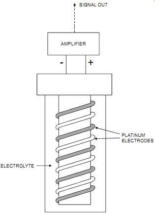
FIG. 4 Amperometric cell. ELECTROLYTE; AMPLIFIER; SIGNAL OUT; PLATINUM ELECTRODES
====
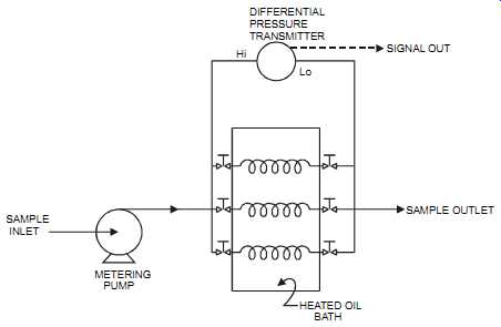
FIG. 5 Capillary tube viscosimeter (shown with three capillaries immersed
in a bath to keep them at a constant temperature). SAMPLE INLET METERING;
PUMP HEATED OIL BATH SAMPLE OUTLET Hi Lo DIFFERENTIAL PRESSURE TRANSMITTER
SIGNAL OUT
====
Application Notes:
The capillary tube has a precision of +/- 1 percent of full scale. It requires that the sample be clean and that pressure pulses be avoided. It also requires that its components be maintained at a constant temperature.
Catalytic
Principle of Measurement:
The catalytic cell consists of two heated platinum sensors. The first, the active sensor, is treated with a catalyst and is sensitive to all combustibles. The second, the compensator or reference sensor, is not treated with a catalyst and therefore won’t respond to combustible gases, but it does have equivalent thermal mass to the active sensor (see figures 6 and 7). The catalyst allows a normally non-flammable mixture to be burned and allows combustion to occur at a temperature below the ignition temperature of the sample gas. To maintain similar electrical characteristics, the reference sensor has the same construction and mass as the detector, but without catalyst. Its main function is to compensate for variations in ambient conditions.
When combustibles are present, they burn at the first sensor. This raises the sensor's tempera ture and therefore changes its electrical resistance. The sensors are incorporated in a Wheat stone bridge. The unbalance in the bridge is amplified and produces an output proportional to the measured variable. Combustible gases are diffused through a flame arrestor before reaching the sensors.
===
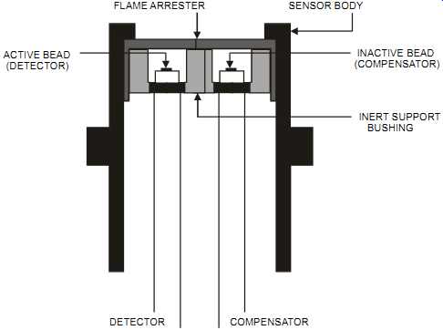
FIG. 6 Explosion-proof catalytic gas detection cell. FLAME ARRESTER SENSOR BODY
ACTIVE BEAD; (DETECTOR) INACTIVE BEAD (COMPENSATOR) INERT SUPPORT BUSHING;
DETECTOR; COMPENSATOR
===
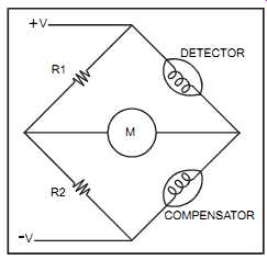
FIG. 7 Catalytic cell circuit diagram. R1 R2; DETECTOR COMPENSATOR
====
Application Notes:
The catalytic cell is commonly used to detect combustible gases. It has a typical temperature range of -67 to 212 °F (-55 to 100 °C). However, this range will vary considerably from one design to another. It has an error of +/- 1 to 5 percent, is versatile, small in size, simple in design, and rugged. It has a relatively low cost, responds well to high gas concentrations and to oxygen-deficient atmospheres, and is simple to calibrate and maintain. However, the catalytic cell is typically limited to concentrations above 1000 ppm. It has a life expectancy of less than two years depending on the detector design and on the gas being measured. This unit has four common failure modes: corrosion, poisoning, inlet blockage, and burnout. It’s affected by the presence of CO and hydrocarbons. Also, in some models, it’s susceptible to H2S, lead, or sili cones poisoning (however, some sensors are poison-resistant). It has a typical warm-up time of about 45 minutes, with a response time of 10 to 30 seconds. The catalytic cell requires oxygen for the oxidation process and constant flow and temperature for the sample (also corrosive gases or vapors, dusts, and entrained liquids should not be present). The catalytic cell is affected by the lack of oxygen, which decreases the burning ability at the active sensor.
Chemiluminescence
Principle of Measurement:
The chemiluminescence technique combines the NO and ozone inside a vacuum chamber.
When NO and ozone are combined, they produce NO2 and light. The light produced is proportional to the NO2 (and original NO) concentration. The light is then measured and converted into a signal output (see FIG. 8). To measure NO2, the gas is first converted into NO and then combined with ozone.
Application Notes:
The chemiluminescence technique is highly sensitive and easy to maintain. It measures a range from 0.1 ppm to 1 percent, has an accuracy of +/- 1 to 2 percent of full scale, and a drift of about 3 percent per week. The unit is commonly used to measure NOx on a continuous basis. It meets CFR 40 Part 60 (Method 73) when it’s measuring NOx, and can handle sample temperature ranges of 32 to 122 °F (0 to 50 °C) and pressures of 0 to 20 psig (0 to 140 Kpag). The chemiluminescence technique has a response speed of 5 to 60 seconds (depending on the analyzer model) and a warm-up time of about an hour. It typically requires a 2 micron sample gas filter. However, this technique is relatively expensive and is affected by the presence of CO2, O2, N2, H2O, hydrocarbons, and ammonia (NH3).
====
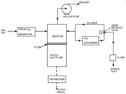
FIG. 8 Chemiluminescent NOx analyzer. DRY AIR OZONE (O) GENERATOR 3 REACTOR
PHOTO MULTIPLIER FILTER TRANSDUCER OUTPUT SIGNAL NO CONVERTER X VACUUM
PUMP EXHAUST NO MODE SOLENOID VALVE FILTER SAMPLE INLET
====
Conductivity
Electrolytic conductivity refers to the ability of a solution to carry an electric current. In gen eral, the more ions there are in a solution, the greater its conductivity. In conductive solids, the flow of electricity is accomplished by the movement of electrons; in solutions, the current is carried by all ions (positive and negative). The conductivity of a solution depends on the ions' mobility and presence. The ions' mobility depends in turn on the dielectric constant of the solution, on the ions' charge and size, and on the solution's temperature. As temperature increases, ion velocity increases, which increases the ions' mobility. Also, as the temperature increases, the solution's viscosity decreases. This reduces the resistance (or drag) on the ions' movement, which also increases their mobility. The conductivity of a solution varies with temperature changes and is a key factor in how accurate a conductivity measurement is. Therefore, such temperature changes must be compensated for.
Conductivity is normally measured in microsiemens/cm. Ultra-pure water has a conductivity of 0.05, distilled water a conductivity of 3.0, milk of 45, and sodium hydroxide (10% weight) of 355,000. Whereas conductivity measures the total ions, pH only responds to the concentration of hydrogen ions. Conductivity measurement is nonspecific, that is, measurements cannot identify one ion from the other.
Principle of Measurement:
A conductivity-measuring system consists of the conductivity cell (the source of most difficulties) and the resistance-measuring instrument (the transducer). There are two basic types of conductivity cells: electrode cells and electrodeless induction cells. The electrode type was originally designed for lab applications and consists of two (or four) metal electrodes in an insulating chamber. The electrodes are generally coated with a deposit of spongy black platinum to increase the effective surface. An AC Wheatstone bridge is the most commonly used resistance-measuring instrument because it’s sensitive, stable, and accurate. The current is introduced into the system and leaves it through the metallic electrodes. The four-electrode design is commonly used for high-conductivity measurements (up to 1 S/cm) and will work well in dirty solutions. An alternating voltage is applied across the conductivity electrodes (which are in contact with the process). The resulting current is proportional to the solution's conductivity.
Each cell has a cell constant-this is the distance between the electrodes divided by the electrode area. With a low cell constant (e.g., 0.1/cm) the electrodes are relatively close together, which is suitable for high-resistivity solutions. However, a low cell constant will tend to become plugged from dirty fluids (due to the restricted passage). Cell constants are available from 0.01/cm to 50/cm, but in most industrial applications, the cell constant varies between
0.01/cm and 10/cm The cell must be matched to the solution being measured to provide an accurate measurable range. A cell with a large electrode area will perform better than one with small electrode areas (hence, the spongy platinum deposit). The sensor should be completely immersed in the solution, and the cell should not trap air or collect sediments. The cell location should avoid poor circulation (e.g., dead-end pipe). The velocity should not be too high since this damages the cell physically. If the velocity is low, the flow should enter the open end of the cell.
The electrodeless induction type of cell consists of a pair of toroidal coils mounted so that a stream of solution penetrates both toroidal holes. It’s the equivalent electrical circuit of two transformers. The first transformer consists of the input toroid as the primary and the closed loop solution as the secondary (a small current is generated from the ions moving in the con ducting loop solution). The second transformer consists of the closed-loop solution as the primary and the output toroid as the secondary (see FIG. 9). The electrodeless induction type of conductivity electrode has many advantages. Because it has no electrodes in contact with the process, it can be used to cope with severe conditions (suspended solids, slurries, abrasive or corrosive materials, very highly conductive materials, etc.). It can also handle up to 390°F (200°C) and 285 psig (2000 KPag) processes. However, it requires that non-conductive piping be used (or a nonconductive liner in a metallic pipe).
Application Notes::
The conductivity-measurement system provides continuous measurement and is highly sensitive, with an accuracy of +/- 1 to 2 percent of full scale. Moreover, it’s simple in design, has a reasonable cost, and is easy to maintain. It can be simplified by using self-diagnostics, where the transducer can detect and alarm internal circuit malfunctions, shorted or open electrodes, or a fouled cell. The conductivity-measurement unit provides conductivity measuring ranges of 0 to 2 microsiemens/cm up to 0 to 1,000,000 microsiemens/cm and can handle process pressures of up to 500 psig (3500Kpag) and 390°F (200°C). Conductivity measurement is used for liquids and has a response time of 2 to 20 seconds for the electrode type and 20 to 60 seconds for the electrodeless (toroidal) type. When compared to pH, conductivity provides easy installation, low maintenance, high reliability, and relatively low cost. However, the elements should be kept clean and should not be exposed to dirty or oily solutions.
===
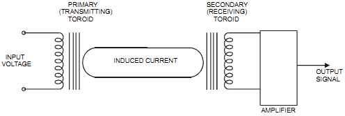
FIG. 9 Electrodeless conductivity cell. INPUT VOLTAGE INDUCED CURRENT OUTPUT
SIGNAL AMPLIFIER PRIMARY (TRANSMITTING) TOROID SECONDARY RECEIVING) TOROID
===
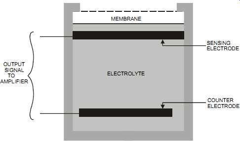
FIG. 10 Electrochemical sensor. MEMBRANE ELECTROLYTE OUTPUT SIGNAL TO AMPLIFIER
SENSING ELECTRODE COUNTER ELECTRODE
===
Electrochemical Principle of Measurement:
The electrochemical cell appeared in the 1950s and was primarily used to measure oxygen. In its simplest form, it consists of two metallic electrodes (a sensing electrode and a counter electrode) that are in contact with an electrolyte. pH probes are a type of electrochemical sensor.
The electrodes and electrolyte are enclosed behind a membrane. The chemical reaction in the cell produces a voltage output that is proportional to the number of ions diffusing between the electrolyte and the electrode (see FIG. 10). The molecules to be measured permeate the membrane and react with the electrolyte. Drying out the electrolyte will reduce the life and performance of the sensor. Plants typically incorporate a temperature compensation method to compensate for the changes in diffusion rates when the temperature changes.
The fluid to be measured passes through a membrane that limits the flow of fluid entering the sensor. The fluid then reacts with the sensing electrode. Selective reactions are matched with an electrode material, and an electrolyte is selected for the fluid to be measured.
Application Notes:
The electrochemical cell is sensitive and can operate from 23 to 104 °F (-5 to 40°C) and with process pressures of up to 150 psig (1000 Kpag). The unit provides a sensitivity as low as 1 ppb (some units claim to go as low as 0.1 ppb), a range as high as 0 to 1000 ppm, and an accuracy of +/- 2 to 3 percent. The electrochemical cell can detect many gases, offers low cost, is easy to install, and requires little power to operate. It’s widely used and has an expected life of one to two years (with a calibration interval of one to eight weeks, depending on the cell and on the application). It’s available as a portable instrument, is commonly used to detect toxic gases in ppm ranges, and can provide a response time that varies between 5 and 60 seconds, depending on the selected model, the required accuracy, the selected range, and the measured fluid.
However, the electrochemical cell is typically limited by two factors: the varying pH of the solution being measured and the presence of other ions, which interfere with the measurement of the ion of interest. However, this interference can be minimized by biasing the electrode's potential and by selecting the correct electrode material. In addition, the electrochemical cell is subject to poisoning, cross-interference, and electrolyte leakage and dry out.
Flame Ionization Detector (FID)
Principle of Measurement:
The flame ionization detector, which is used in gas chromatography, burns hydrocarbons in a hydrogen/air flame. It’s the most common analyzer for measuring total hydrocarbons. Carbon ions released from the combustion are sensed through electrons around an electrode in the flame. The current measured is proportional to the number of carbon atoms in the flame, that is, the concentration of hydrocarbons. The detector cell, where the combustion occurs, is regulated at a fixed temperature, typically, 80°C +/- 1°C.
===
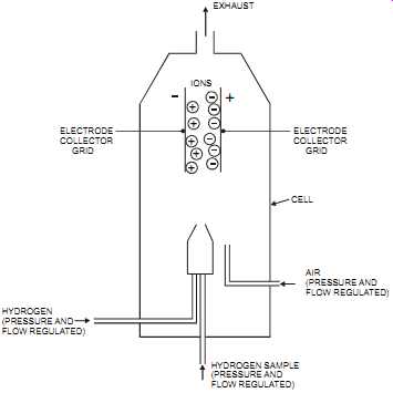
FIG. 11 Flame ionization detector. IONS ELECTRODE COLLECTOR GRID ELECTRODE
COLLECTOR GRID EXHAUST CELL AIR (PRESSURE AND FLOW REGULATED) HYDROGEN
(PRESSURE AND FLOW REGULATED) HYDROGEN SAMPLE (PRESSURE AND FLOW REGULATED)
===
Application Notes:
The flame ionization technique is highly sensitive. It has an accuracy of 1 to 2 percent of full scale, provides a wide linear range of response and continuous measurement, and has a typical response time of 1 to 10 seconds (depending on model). It has the ability to measure ranges as low as 0 to 1 ppm with resolutions of 0.01 ppm. Flame ionization units are available at moderate cost and are easy to maintain.
Flame ionization requires a sample flow rate of about 4 L/min, a fuel flow (hydrogen) of about 50 mL/min, and a zero grade (THC < 1ppm) air flow of about 400 cc/min at 25 psig minimum (175 Kpag). Flame ionization units also require a gaseous sample and should be calibrated for each component to be measured. However, these units require absolutely clean (hydrocarbon free) air to operate correctly and so must be cleaned in environments where samples generate ash or soot in the flame. To prevent flooding of the detector, the unit should be designed so that water produced by the hydrogen flame (from condensation) is swept away from the detector.
Fourier Transform Infrared (FTIR)
Principle of Measurement:
The Fourier transform infrared (FTIR) analyzer consists of an infrared source (typically a heated coil of wire), an interferometer, a sample cell, and a detector. The heart of the FTIR system is the interferometer (see FIG. 12). It consists of two mirrors: a fixed mirror and a moveable mirror. The performance of an FTIR is largely dependent on the correct alignment of both mirrors.
===
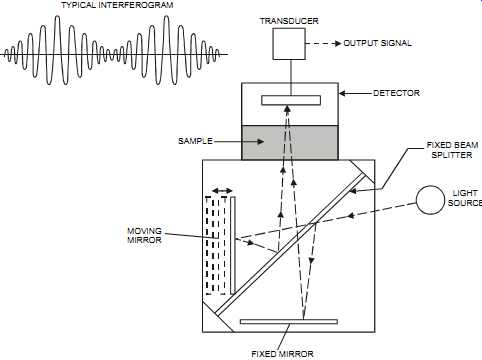
FIG. 12 Interferometer in a FTIR analyzer. TYPICAL INTERFEROGRAM FIXED
BEAM SPLITTER; LIGHT SOURCE FIXED MIRROR MOVING MIRROR TRANSDUCER OUTPUT
SIGNAL DETECTOR SAMPLE
===
The FTIR analyzer is similar to the non-dispersive infrared detector (NDIR). However, NDIR detectors are dedicated to monitoring a single component, whereas the FTIR detectors can pro vide analysis of multiple components (see section on NDIR later in this Section). Most industrial chemicals absorb infrared radiation in a specific manner. This absorption is then measured by the infrared analyzer (including FTIR and NDIR). The difference is that in the Fourier transform method, a modulation/demodulation process occurs. Typically, an infrared source is collimated and sent to an interferometer, where a beam splitter splits the radiation into a transmitted and a reflected beam. The transmitted beam goes to a moving mirror, and the reflected beam goes to a fixed mirror. Through the mirrors, the beams are recombined to produce an interference pattern. When the beams are exactly identical in length, light frequencies will combine constructively. The moving mirror creates path lengths that are different from the fixed mirror path. As the moving mirror moves at a fixed velocity, cycles of constructive and destructive interference occur because of the path difference, that is, the phase difference, between the two beams on recombination at the splitter. This composite pattern (called an interferogram) is the Fourier transform of the infrared spectrum.
Thus, an FTIR analyzer produces an instantaneous spectrum for all wavelengths in contrast to NDIR analyzers, which produce only a portion of the spectrum covering a narrow wavelength range. Interferometers are single-beam instruments. The specific concentration data is mathematically calculated from the measured spectrum by identifying spectral "fingerprints" rather then individual peaks (see section on infrared absorption later in this Section). The appearance of affordable computers provided the necessary power to perform the Fourier transform so as to fit the analysis of peaks and spectral fingerprinting. The sensitivity of this analyzer is proportional to the length of the measuring cell, which typically varies between 1 mm to 1 meter for a fixed path length and 1 meter to 100 meters for multiple internal reflection (MIR) cells.
Application Notes:
The Fourier transform infrared (FTIR) is more sensitive than infrared (dispersive IR) and NDIR because of the increased infrared energy at the detector. It can measure gases and liquids continuously and can measure solids if they are thin enough (such as moving films). It may also measure thicker solids by reflection from the surface. The FTIR unit is rugged and reliable, has a response speed of 1 second to 5 minutes (but typically around 30 seconds), and has an accuracy (at best) of around +/- 1 percent. The FTIR is easy to maintain, can detect airborne pollutants in an atmospheric open path within a few tens of ppb over distances up to 6 miles (10 km), and can measure multiple components (typically limited to 6 to 15 per stream). Errors are introduced into FTIR measurements from non-linearities and from noise. The unit requires that extreme precision be exercised when aligning the interferometer in order to maintain the interferometer's accuracy and field alignment (for units that are not permanently aligned). Thus, calibration could be an expensive maintenance item. FTIR units require accurate data on the spectral signatures of all the components that will be in the sample. Any changes in the sample's composition will necessitate recalibrating the analyzer. The FTIR's infrared source must be replaced frequently, typically yearly.
Gas Chromatograph
Principle of Measurement:
The gas chromatograph (also sometimes referred to as a "gas liquid chromatograph") consists of a carrier gas system, a sample injection valve, a separation column, a detector, a column oven, and a controller that provides the method for controlling the analyzer system. The gas chromatograph measure the concentration of multi-component mixtures. This method is used for gases and liquids as long as the components to be measured are volatile and don’t decompose in the vapor phase. The technique is not continuous. It works by separating the constituents of a mixture from an injected sample, then measuring the concentration of each component as it passes through a detector.
===
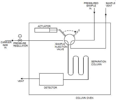
FIG. 13 Gas chromatograph. SAMPLE VENT PRESSURED SAMPLE IN ACTUATOR SAMPLE
INJECTION VALVE SEPARATION COLUMN CARRIER GAS IN PRESSURE REGULATOR VENT
DETECTOR COLUMN OVEN
===
The carrier gas system typically consists of gas bottles containing a high-purity carrier gas (such as nitrogen, helium, or hydrogen), pressure regulators, and flow controllers (such as needle valves). Theoretically, any gas that is pure and inert can be used as a carrier. Care must be taken to ensure that no contaminants are introduced through the carrier gas system.
The sample injection valve injects a fixed sample gas volume into the carrier gas and onto the column on a timed basis. It’s a high-precision device that meters a gas sample of 0.1 to 2.0 milliliters.
The separation column separates the sample components based on their boiling point, polarity, or other separation criteria. It consists of a tube that is packed (or coated) with a material that produces a retarding effect on the components passing through it. Different packing materials and column temperatures provide the means for changing the component separation. The components will come out of the column at different times, with all the molecules of a component emerging together in a defined time span. That is, these components are presented to the detector in batches. Corrosive materials or particles in suspension must be avoided to maintain the column's effectiveness.
The detector is a very sensitive device that measures the concentration of the different components emerging from the column. The detector could be a thermal conductivity sensor, flame ionization sensor (which measures down to ppb), or one of many specialized detectors some times used for specific applications. The sample is typically measured at a constant tempera ture and pressure.
The column oven is insulated and temperature controlled. It encloses the sample inject valve, the separation column, and the detector. The column oven provides stability and an optimum temperature of 60 to 200°C for the separation process. The temperature control loop typically uses electrically heated circulated air to maintain the oven temperature to a fraction of a degree.
Application Notes:
The gas chromatograph is highly accurate and very versatile. It can measure from parts per billion (ppb) to 100 percent. It’s commonly used to measure hydrocarbons but can measure other gases with proper column and detector combinations. The gas chromatograph can measure multiple components and handle process temperature ranges of -20 to 350 °F (-28 to 176 °C) and pressures of 10 to 1200 psig (70 to 8400 Kpag). It’s used only where the sample is vaporizable, and it must receive a representative sample. Gas chromatographs are relatively slow to respond.
Gas chromatographs should be positioned away from high-vibration areas and must be operated by particularly well-trained maintenance personnel. Expensive to purchase and maintain, gas chromatographs are not easy to maintain, requiring about one man-month per year.
They produce a cyclical rather than continuous analysis (it is a batch operation). Gas chromatographs are therefore not used on fast loops or where instant analysis is required, but rather as a process check or in trimming control signals. They require a sampling system that consumes a bottled carrier gas.
Infrared Absorption
Principle of Measurement:
When infrared radiation impacts a molecule with a frequency that is identical to the molecule's specific vibrational frequency, energy from the infrared beam will be absorbed in the molecule.
The operation of the infrared analyzer is related to the Beer-Lambert law: with a constant cell length and a constant absorption coefficient for a compound X at a fixed wavelength, the measured absorbance is directly related to the concentration of compound X.
The concentration of one material can be determined in the presence of another material as long as the wavelength of light chosen is absorbed only by the material under measurement and not by any other material. It’s therefore essential to know the concentrations of all the components in a sample. Infrared absorption is based on vibrational frequency, and infrared absorption units are less sensitive than ultraviolet sensors (see section on UV sensors). The infrared absorption consists of an infrared source, two optical filters (a measure filter and a reference filter), a sample cell, and an infrared detector (see figures 3-14 and 3-15). The infra red source is usually a nichrome element that has been heated to a dull red color. The infrared region of radiant energy has longer wavelengths than those of visible light. As the temperature of a component increases, the wavelength of the emitted radiation decreases. The amount of emitted radiation forms a curve that is a function of wavelength or frequency. The source pro vides a continuous beam of radiation that represents the portion of the spectrum in which the sample will be absorbed. The measure filter then limits the radiation to the desired wavelength.
The reference filter is selected such that none of the measured components nor the background components can absorb infrared energy. The reference filter compensates for background energy changes. Typically, the beam is mechanically chopped by a chopper wheel on which two filters are mounted. The radiation then passes through the cell, through which the fluid being analyzed is flowing. Cell path lengths vary from 0.025 mm for liquid service to 1 m for high-sensitivity gas applications. The detector compares the received infrared energy with that of a reference wavelength (typically, between 1 to 10 nanometer). It then sends its signal to a transducer. New infrared absorption instrument designs have a single source that is split into a reference beam and a sample beam. This approach eliminates the problem of two sources decaying, over time, at a different rate, thereby causing an error between the two beams.
Two common variations of industrial infrared sensors are the non-dispersive infrared (NDIR) detectors, which are dedicated to monitoring a single component, and the Fourier transform infrared (FTIR) detectors, which can perform multi-component analysis. Refer to the sections on NDIR and FTIR analyzers for further information. Dispersive infrared analyzers are commonly used in protected locations such as a laboratory.
The sensitivity of the infrared absorption analyzer is proportional to the length of the measuring cell (which typically varies between 5 mm to 1 meter for gases and 0.01 to 1 mm for liquids). Solid samples are measured as a thin film or as a powder suspended in an infrared transparent binder (such as mineral oil).
===
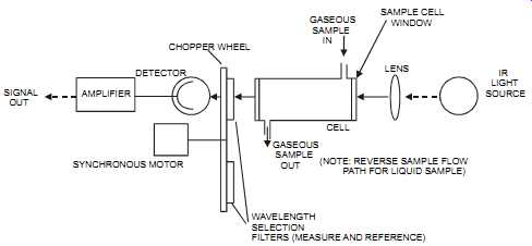
FIG. 14 Single-beam, single-detector, dual-wavelength IR analyzer. SIGNAL
OUT AMPLIFIER DETECTOR SYNCHRONOUS MOTOR CHOPPER WHEEL GASEOUS SAMPLE
IN CELL GASEOUS SAMPLE OUT SAMPLE CELL WINDOW LENS (NOTE: REVERSE SAMPLE
FLOW PATH FOR LIQUID SAMPLE) WAVELENGTH SELECTION FILTERS (MEASURE AND
REFERENCE) IR LIGHT SOURCE
===
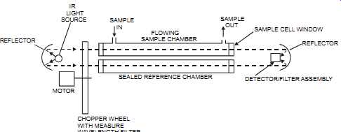
FIG. 15 Dual-beam, dual-chamber, single-detector IR analyzer. IR LIGHT
SOURCE REFLECTOR MOTOR SAMPLE IN FLOWING SAMPLE CHAMBER SAMPLE OUT SEALED
REFERENCE CHAMBER CHOPPER WHEEL WITH MEASURE WAVELENGTH FILTER SAMPLE CELL
WINDOW DETECTOR/FILTER ASSEMBLY REFLECTOR
===
Application Notes:
The infrared absorption detector can, in theory, measure from as low as 0 to 10 ppm, with sensitivities of 0.1 to 1 ppm, and up to 100 percent (v/v). Practically, however, the low range is between 200 and 500 ppm. The infrared absorption detector has a linear response, provides a continuous measurement, will respond within 3 to 5 seconds, and has an accuracy of +/- 0.5 percent of span with a +/- 1 percent drift every 24 hours. It’s rugged and can operate, with proper maintenance, for long periods of time. This detector is used for gases, vapors, and liquids (and even for thin-film solids or powders). However, it needs to operate at a constant cell pressure for gases; a 1 percent change in cell pressure will cause a 1 percent measurement error. The infrared absorption detector also requires a sample that is clean, dust free, and with out condensate.
The infrared absorption detector is commonly used to measure CO, CO2, SO2, NO, and ammonia. It meets CFR 40 Part 60 (method 10) for CO measurement, CFR 40 Part 60 (method 3A) for CO2 measurement, and CFR 40 Part 60 (method 26) for HCl measurement. Its cost is relatively low and maintenance is easy. The unit requires typically about two man-weeks per year for maintenance.
The infrared absorption detector may have difficulty measuring components that have similar molecular structures since their absorption bands overlap. It will also experience interference as a result of moisture and temperature changes.
Mass Spectrometer
Principle of Measurement:
The mass spectrometer consists of six basic components: the inlet system, the ion source, the separator, the detector, the vacuum system, and the electronics/controller (see FIG. 16). It’s one of the most powerful and versatile analyzers on the market. Mass spectrometers can analyze most components that can be vaporized and are compatible with the analyzer's operating temperature; it’s a universal analyzer.
The mass spectrometer's inlet system introduces a small sample into the ion source by using a flow-by capillary or a membrane. The spectrometer's design must ensure that the introduced sample is a true representation of the fluid; therefore, sample fractionation must be avoided.
The spectrometer's inlets are commonly heated to vaporize the liquid samples and to maintain gas samples above their dew points.
The ion source bombards the sample with electrons, forming a gaseous mixture of ionic fragments that drift into the analyzer. Positive ions are measured by injecting them into the separator. The separator separates the ions according to their mass-to-charge ratio. There are two types of separators: the quadrupole and the magnetic sector. In the quadrupole separator, the fragments are separated by a combination of DC electric fields and radio frequency. The magnetic sector separator uses a magnetic field to separate the ion beam, which tends to form a segment of a circular orbit. Each type has its advantages and disadvantages. But typically, the quadrupole is smaller, faster, more reliable, and less expensive then the magnetic sector type.
On the other hand, the magnetic sector type is more accurate and more stable and requires less frequent calibration.
The mass spectrometer detector produces a voltage that is proportional to the ion beam that strikes it, which in turn is proportional to the amount of a particular component in the sample.
The vacuum system creates a very low pressure in the system so as to avoid the collisions between the ions and gas molecules. This also increases the probability that the ionizing electrons do ionize the sample.
====
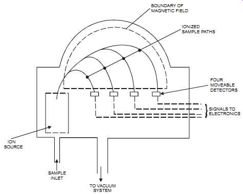
FIG. 16 Mass spectrometer (magnetic sector type) for the measurement of
four components in a sample. ION SOURCE SAMPLE INLET TO VACUUM SYSTEM
FOUR MOVEABLE DETECTORS SIGNALS TO ELECTRONICS IONIZED SAMPLE PATHS BOUNDARY
OF MAGNETIC FIELD
====
The system's electronics, including a personal computer (PC), identify the results from the detector and compare their fingerprint to a database, thereby identifying the components. The PC controls the analyzer, tunes the system, and calculates the component concentrations.
Application Notes:
The mass spectrometer has a fast and linear response. What may take ten minutes to analyze with another method, takes ten seconds with a mass spectrometer. It provides a highly reproducible measurement for a given set of conditions, offers an equal sensitivity to all components, and can measure up to 16 different components from a single stream.
The mass spectrometer provides continuous measurement and is used for gases, vapors, and liquids. The unit measures from ppb (but typically ppm) to 100 percent and has a sensitivity of about 0.01 percent with a measuring error of +/- 1 to 2 percent. However, it requires a sample that can be vaporized (when measuring chlorine or acid gases, the sample should be dry). Typically, it also requires special manifolds and valves for automatic calibration (they are con trolled by the PC). The unit may change the form of the sample as a result of the vacuum that is produced. The vacuum may also bring in background gases, which introduce noise into the measured signal.
The analyzer of a mass spectrometer must be tuned every one to two months, and it’s essential that maintenance personnel receive extensive training in its maintenance. Maintenance is complex, and the mass spectrometer's initial cost is high.