AMAZON multi-meters discounts AMAZON oscilloscope discounts
Principle of Measurement:
Non-dispersive infrared systems (NDIR) are a type of infrared detector (see the earlier section in this Section on infrared absorption). In the preferred dual-beam NDIR instrument, the infra red beam is split in two, with one beam passing through a sample cell and the other through a reference cell (see FIG. 17). The component in the sample cell will absorb radiation, whereas the radiation passes through the non-absorbing reference cell. IR radiation is absorbed by the sample molecules, which results in a detector imbalance. This imbalance is sensed by the detector and transmitted to a transducer.
NDIRs are dedicated to monitoring a single component, whereas FTIR detectors can provide multi-component analysis. NDIRs are available in single- or dual-beam types. The dual-beam NDIR has a separate reference cell and is used more frequently then single-beam NDIRs. The single-beam is cheaper, whereas the dual-beam is more sensitive and more stable, but costs more.
The stability of NDIR analyzers can be improved with the use of a single infrared light source, where a curved mirror is used to split the beam equally to the sample and reference cells. The sensitivity of this analyzer is proportional to the length of the measuring cell (which typically varies between 1 mm to 1 meter).
===
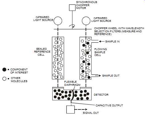
FIG. 17 Dual-beam non-dispersive infra-red (NDIR) analyzer. COMPONENT OF INTEREST
OTHER MOLECULES SEALED REFERENCE CELL FLEXIBLE DIAPHRAGM INFRARED LIGHT SOURCE
SYNCHRONOUS CHOPPER MOTOR INFRARED LIGHT SOURCE CHOPPER WHEEL WITH WAVELENGTH
SELECTION FILTERS (MEASURE AND REFERENCE) SAMPLE IN FLOWING SAMPLE CELL SAMPLE
OUT DETECTOR CAPACITIVE OUTPUT SIGNAL OUT
===
Application Notes:
The NDIR detector can have a range of 0 to 5000 ppm (though typically it’s 10 - 100 ppm) with a resolution of 0.1 to 10 ppm. It’s often used as an open-path detection device for up to 650 feet (200 meters) in hydrocarbon applications or down to 1.5 ft (0.5 meters) for stack installations. The NDIR has a response time of 0.5 to 20 seconds (though typically 2 to 5 sec), with an accuracy of +/- 1 to 3 percent of full scale, depending on the component being measured and on the analyzer. The unit meets 40 CFR 60 and 75 when measuring CO and CO2. It can measure moisture in a 0 to 95 percent range, with a +/- 0.5 percent accuracy, and typically requires about four hours to calibrate.
Paper Tape
Principle of Measurement:
In the paper tape technique, a chemically impregnated tape is drawn mechanically across a sample inlet where it comes into contact with a metered gas flow. If the component to be measured is present, a reaction takes place on the tape, and a colored stain is developed. An optical system illuminates the tape, and the reflected light is measured. The intensity of the stain is proportional to the concentration of the metered gas flow.
Application Notes:
The paper tape analyzer, which is available as a battery-powered portable unit, can measure down to ppb and is reasonably accurate. It can operate within 32 to 104 °F (0 to 40 °C), is relatively inexpensive, and can be maintained simply and relatively quickly. In addition, it has a response time of 10 to 250 seconds (depending on the gas being measured).
===
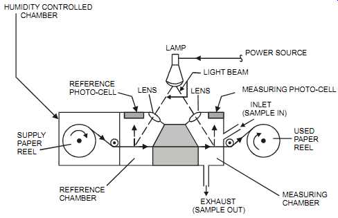
FIG. 18 Paper tape analyzer. HUMIDITY CONTROLLED CHAMBER REFERENCE PHOTO-CELL
LENS; LIGHT BEAM MEASURING PHOTO-CELL; INLET (SAMPLE IN) USED PAPER REEL
MEASURING CHAMBER EXHAUST (SAMPLE OUT) REFERENCE CHAMBER SUPPLY PAPER REEL
LAMP POWER SOURCE
====
Paramagnetic
Principle of Measurement:
The paramagnetic measurement technique (also known as "magneto dynamic") is dedicated to measuring oxygen. It’s based on the physical principle that oxygen atoms are paramagnetic, that is, are attracted into a magnetic field. With some exceptions (see following Application Notes:), most other species of atoms are diamagnetic (i.e., repelled by a magnetic field). In paramagnetic measurement devices, a small mirror is suspended between the poles of a magnet.
When the gas containing the oxygen flows through the gap it deflects the mirror, and the degree of deflection is detected optically and amplified to give a direct measurement of oxygen concentration.
Application Notes:
The paramagnetic detector is reasonably inexpensive and has a response time of 2 to 70 seconds (depending on the selected unit). It has an accuracy of +/-1 to 2 percent of range, a sensitivity of about 0.01 percent, and a sample temperature range that varies from about 32 to 110°F (0 to 44°C). The paramagnetic detector's maintenance requirements are low; it requires about two hours to recalibrate. However, it can only measure oxygen on a dry basis; for the wet measurement of O2, the zirconia cell should be used. The paramagnetic detector also requires a low sample pressure; 10 psig (70 Kpag) is a typical maximum. The paramagnetic detector will experience measurement interference from NO, so it could therefore be used for measuring NO in the absence of O2. In addition, the detector is susceptible to the presence of nitric oxide, nitrogen dioxide, chlorine dioxide, carbon monoxide, carbon dioxide, and certain hydrocarbon gases (CH4, etc.) since these gases are also paramagnetic. For this reason, plants requiring low measuring ranges (2% or less) should be aware that background gases may cause significant errors. The paramagnetic detector also requires a sampling system and is susceptible to vibrations.
====
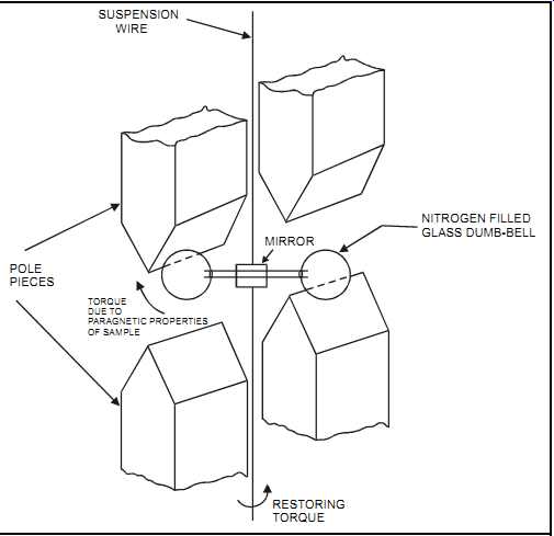
FIG. 19 Paramagnetic analyzer. POLE PIECES TORQUE DUE TO PARAGNETIC PROPERTIES
OF SAMPLE MIRROR NITROGEN FILLED GLASS DUMB-BELL RESTORING TORQUE SUSPENSION;
WIRE
====
pH
pH measures the concentration of hydrogen ions in a solution and is an indication of the solution's acidity or alkalinity. Therefore, the strength of an acid solution is indicated, through a logarithmic scale, by the number of hydrogen ions available. For example, a pH of 5 means that the hydrogen ion concentration is 0.00001 grams/liter at 25°C. The smaller the pH number, the greater the hydrogen ion concentration and, therefore, the solution's acidity.
The normal pH measuring range is 0 to 14. A pH of 7 at 25°C is for neutral (pure) water.
Acidic solutions have a pH < 7, whereas alkaline solutions have a pH > 7 (i.e., a lower hydro gen ion concentration than an acidic solution). A pH of 0 is measured for 3.5 percent hydrochloric acid and a pH of 14 for 4 percent sodium hydroxide. The hydrogen ion concentration will increase ten times when the pH value drops by one. A pH of 7 has ten times the acidity of a pH of 8. So to reduce the pH of a solution from 6 to 5 requires ten times the amount of acid required to reduce the pH from 7 to 6.
Principle of Measurement:
In pH measurement, an electrochemical sensor consisting of three electrodes-the glass electrode, the reference electrode, and the temperature electrode-is connected to an amplifier.
===
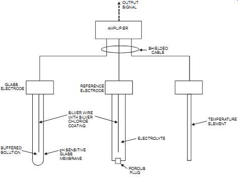
FIG. 20 pH sensor with diffusion-type reference electrode. GLASS ELECTRODE
REFERENCE ELECTRODE SILVER WIRE WITH SILVER CHLORIDE COATING BUFFERED SOLUTION
pH SENSITIVE GLASS MEMBRANE ELECTROLYTE OUTPUT SIGNAL AMPLIFIER SHIELDED
CABLE POROUS PLUG TEMPERATURE ELEMENT
===
Glass electrode. The glass electrode provides a potential that is proportional to the hydrogen ion concentration (pH value) of the solution. It consists of a glass membrane that contains a standard solution with a known hydrogen ion concentration in which is inserted an electrical conductor. The glass membrane is a poor conductor (i.e., has high impedance). The glass selected for the membranes of the electrodes must be compatible with the process fluid temperature and its pH value. When immersed in a solution, the potential developed across the glass membrane is measured between the electrode of the glass electrode and the electrode of the reference electrode. Glass electrodes are the most commonly used measuring electrodes. When immersed in a solution, they gradually reach equilibrium with the ions present in the solution and maintain equilibrium as the ionic strength of the solution changes.
The voltage developed between the measured solution and the standard solution in the glass electrode is caused by the difference in the ion concentration between the two solutions. When the glass electrode is immersed in an aqueous solution, a gel layer forms on the glass. That is, the electrode becomes "wetted" (for an alkaline solution, the hydrogen ions diffuse out, and the outer gel layer gets a negative charge, and vice versa for an acidic solution). Minute cracks in the glass membrane, not visible to the naked eye, will cause a constant reading of pH=7, that is, input of 0 mV. The electrode must be conditioned for a 24-hour period before it’s used (i.e., left in solution) in order for the gel layer to generate on the surface of the glass. To prevent dehydration, the pH electrode should be stored in a wet environment. Extensive dehydration will ruin the pH electrode. pH probes should preferably be stored in a buffered solution, but if that is not available, tap water will do. The electrode may be preconditioned (memory effect) by exposing it continuously to a solution with a pH >10. As a result, the electrode won’t respond well for low pH solutions, so specially formulated electrode membranes should be used.
Reference electrode. The reference electrode provides a constant potential regardless of the solution in which it’s immersed. This potential is used as the reference from which to measure the variable potential produced by the glass electrode. The pH reference probe must be a good conductor (i.e., have low impedance) with the solution to be measured. There are two main types of reference electrodes: the diffusion type (where the electrolyte diffuses through a porous area) and the flowing type (where a small amount of electrolyte flows out of the reference electrode). For the flowing-type electrode, positive pressure must be maintained inside the reference electrode. For both types, the electrolyte must be in electric contact with the solution. The reference electrode is affected by coating the porous plug, which results in a gradual drift in calibration until complete plugging occurs. Electrolyte contamination must be avoided.
The reference electrode is directly affected by the presence of poisoning ions, which react either with the electrolyte or with the electrode, causing coating. Typical poisoning ions are found in ammonia, chlorine, and sulfur solutions.
Temperature electrode. The temperature electrode is required to compensate for the varying potential at the glass electrode as a result of temperature changes. Temperature affects pH measurement in two ways: on the electrodes and on the solution itself. Employing temperature compensation in pH measurement will correct for the effects on the electrode and not for the changes in the solution's pH (although some transducers have a built-in capability to compensate for that effect as well). Temperature changes cause pH measurement errors in the solution because of the volumetric expansion (or contraction) with temperature, which results in a reduced (or increased) solution concentration.
Combination glass/reference electrodes contain the sensing electrode, reference electrode, and temperature sensor in one unit. They are small and easy to handle. However, the choice of sensing electrodes is limited, and they are more expensive to replace than individual sensing electrodes.
Application Notes:
pH measurement is continuous and applies to liquids only. It’s highly sensitive when the electrodes are kept clean, is reasonably inexpensive, and maintenance is relatively easy to accomplish. pH loops should be run on a continuous basis (rather than on/off). Typically, pH measurement has an accuracy of +/- 0.01 to 2.0 units and a temperature limitation of 210°F (100°C) max, although some special sensors can reach temperatures 30 to 100 percent higher.
The pressure limitation is 140 psig (1000 KPag) max. Some special units can operate under higher pressures.
In spite of their fragile appearance, glass electrodes are relatively robust, are resistant to most solutions, and have a wide pH and temperature range. Different glass formulations should be used for different process applications. For example, hydrofluoric acid will attack the glass material of the typical glass electrode, so an antimony probe should be used instead. Antimony is hard, brittle, and sensitive to temperature changes. In addition, glass probes will introduce errors when they are used with high alkali concentrations. High-purity water has only traces of contaminants and a very low conductivity, so special high-purity water pH sensors must be used. Sudden (and excessive) temperature changes will create a damaging thermal shock on the pH element.
Amplifiers with self-diagnostics facilitate troubleshooting. They typically monitor sensor breakage, fouling, non-immersion, incorrect operation, and time-in-service for the purposes of probe maintenance. Table 2 lists commonly encountered problems in pH measurement and their respective solutions.
===
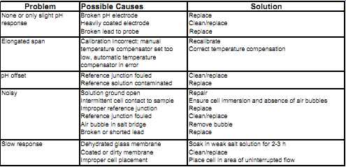
Table 2 Troubleshooting guide: Problem --Possible Causes --Solution
None or only slight pH response Broken pH electrode; Heavily coated electrode; Broken lead to probe; Replace; Replace Clean/replace Elongated span Calibration Incorrect; manual temperature compensator set too low, automatic temperature compensator in error Recalibrate Correct temperature compensation pH offset Reference junction fouled Reference solution contaminated Clean/replace Replace Noisy Solution ground open Intermittent cell contact to sample Improper reference junction Reference junction fouled Air bubble in salt bridge Broken or shorted lead Repair Ensure cell immersion and absence of air bubbles Replace Clean/replace Remove bubble Replace Slow response Dehydrated glass membrane Coated or dirty membrane Improper cell placement Soak in weak salt solution for 2-3 h Clean/replace Place cell in area of uninterrupted flow
===
It’s good practice to locate the electrodes where they are immersed at all times and where the proper flow rate is achieved around the electrodes through proper solution mixing/reaction. pH elements should be easily accessible for cleaning and replacement (see FIG. 21). Some times sampling systems are used; however, they may change the pH of the measured sample as the temperature and/or pressure changes.
Some applications use retractable sensors (hot-tap) so sensors can be easily removed and inserted without shutting down the process. Such insertion probes are supplied with a ball valve and a safety chain to prevent probe ejection.
The probe should be located (see FIG. 22) to avoid oil deposits, static interference (e.g., on plastic vessels and pipework), and shock (e.g., from sudden changes in concentration, pres sure, or temperature). The line containing the probe should be flushed clear after each use and the probe left immersed in water when not in use. In the case of fluids that contain solids, some form of screening is necessary to prevent mechanical damage to the electrodes (see FIG. 23). Slurries with soft particles will tend to coat the electrodes; whereas hard particles tend to pit the electrodes, especially in high-velocity streams. pH electrodes are sensitive to static electrical interference, particularly where plastic pipes and vessels are used. Static charge may easily develop around the pH membrane, causing a noisy signal.
===
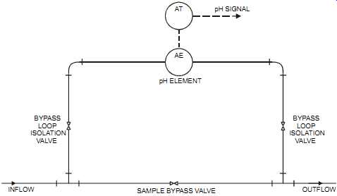
FIG. 21 Flow-through element installation. pH SIGNAL pH ELEMENT AT AE BYPASS
LOOP ISOLATION VALVE BYPASS LOOP ISOLATION VALVE INFLOW OUTFLOW SAMPLE
BYPASS VALVE
===
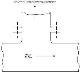
FIG. 22 Probe protection using gravity effect. MAIN FLOW CONTROLLED FLOW
TO pH PROBE
===
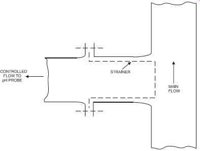
FIG. 23 In-line strainer for probe protection.
===
Control
pH control has its own peculiar problems. The logarithmic term is non-linear, the titration curve is very sensitive near a pH of 7, and extensive dead time is normally present. In addition, the overall complexity of pH control is exacerbated by changes in effluent composition, flow errors in the reagent delivery system, performance degradation of pH probes, and imperfect mixing. In practice, after calibration a pH probe typically shows an error of 0.25 pH.
On its own, feedback control will generally not produce stable control because of the extensive dead time. For that reason, dead time must be minimized where possible. Typically, two or three stages of pH control may be necessary, and some plants add a few tanks in series to attain the desired pH, with each tank contributing ever closer to the pH setpoint. Feedforward offers a simple solution to this problem. It avoids, in many instances, the need to implement multiple tanks. As shown in FIG. 24, the feedforward action compensates for variations in flow and pH in the effluent stream before either one causes an error. Final corrections are performed by the feedback controller (refer to Section 8 for more information on feedforward and feedback).
In most cases, online pH loops will oscillate if the controller set point is on the steep part of the titration curve.
pH control that is performed in tanks will create a time delay. Following these rules may improve performance:
• the residence time T should be > 3 minutes (T=V/F)
• where V = volume of tank and F = effluent flow rate
• good mixing is achieved by using an agitator
• the vessel height should approximately equal the diameter
• the effluent should leave from the side opposite where the flow enters
• the reagent should be added before (and close to) the effluent flow inlet so as to pre-mix
• the pH probe should be located at (or close to) the flow outlet
• pH measurement in a recirculation line (sometimes incorporating an open weir box) makes retrieval or maintenance easy
If pH control is done in a static in-line mixer (see FIG. 25), a pump may be required to pro vide sufficient driving head to overcome the friction of the mixer. This method is used where the pH inlet value varies by 1 unit maximum.
===
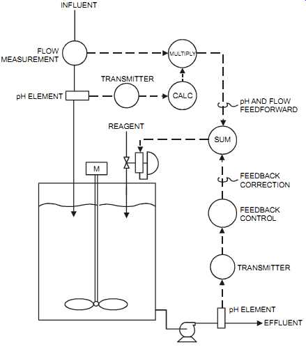
FIG. 24 pH control loop. INFLUENT FLOW MEASUREMENT MULTIPLY TRANSMITTER
CALC REAGENT M SUM pH AND FLOW FEEDFORWARD FEEDBACK CORRECTION FEEDBACK CONTROL
EFFLUENT pH ELEMENT TRANSMITTER pH ELEMENT
===
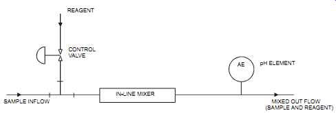
FIG. 25 pH measurement using an in-line mixer. REAGENT CONTROL VALVE SAMPLE
INFLOW IN-LINE MIXER AE pH ELEMENT MIXED OUT FLOW (SAMPLE AND REAGENT)
===
The control valve required to add the reagent(s) should be linear with a 1:50 valve range (remember that pH is a log scale). The valve turndown must meet the process requirements, that is, split-range valving may be required (with two or even three valves), and the output should be linear throughout the range of all valves.
Because of how difficult it’s to implement a correct pH installation that operates effectively, it’s recommended that plants use conductivity measurements where possible. pH should be used only if hydrogen ions, rather than total ions, need to be measured.
Cleaning:
Cleaning the pH electrodes is essential to their proper operation. For example, a 1 mm-thick slime will increase dead time from eight seconds to eight minutes. Grease and oil films coat the electrode and isolate the solution from the glass membrane, which results in a false reading.
Therefore, plant personnel should not touch the sensitive glass area of the element with bare hands. There are three basic methods for cleaning pH electrodes: manual, self-cleaning, and automatic. Note that during cleaning, the measurement signal should be isolated and held until the measurement returns to a steady value. In process environments where pH measurement is required continuously, the plant should make spare electrodes ready for use. In other cases, online backup electrodes, or even a two-out-of-three voting system, can be implemented to ensure continuous reliable measurement. In critical applications, the plant should install three electrodes (for a two-out-of-three vote) since with only two electrodes it’s difficult to identify which one is drifting.
Manual cleaning. In the manual cleaning process a cleaning solution ( For example, 5% muriatic acid) is used. Typically, it takes about 30 man-hours/year to manually clean an electrode that is set under average operating conditions.
Self-cleaning. Self-cleaning is accomplished by locating the electrodes in a high-velocity location that has a flow of 5 to 10 ft/sec (1.5 to 3 m/sec). However, while the impinging flow keeps the electrode clean, extremely high flow velocities will quickly deplete the reference electrode.
Automatic cleaning. Automatic cleaning can be accomplished by using ultrasonic, chemical, brush, or water-jet methods.
In the ultrasonic method, the liquid around the electrodes vibrates, and the cleaning effect is dependent on the vibration energy and the fluid velocity past the electrodes. This method is particularly effective with fine particles and supersaturated sediments, whereas soft or sticky deposits tend to absorb the ultrasonic energy. For ultrasonic cleaning, the electrodes must with stand the ultrasonic energy of approximately 70 kHz.
The chemical method consists of periodically spraying a chemical onto the electrodes, typically a dilute hydrochloric solution. It’s particularly effective with light oils, fatty acids, and materials in suspension. It’s important to ensure that the chemical used won’t interfere with the sensor's operation or affect the process.
The brush method is used periodically (say, once a minute) and consists of moving a brush along the electrodes to prevent sediments from forming. There is no interruption of pH measurement during cleaning, however, sticky material can adhere to the brush and get smeared on the electrodes. The abrasiveness of the brush method may affect the sensor's performance, and it should therefore be used only on abrasion-resistant surfaces.
In the water-jet method, a spray of hot water is periodically aimed onto the electrodes. This method is particularly effective with slime, microorganisms, fatty acids, and clay in suspension. In some applications, the water-jet method is enhanced by introducing air into the water jet, improving the cleaning effect.
Calibration
Typically, calibration is performed weekly (and in some cases, more frequently) using one of three commonly available buffered solutions: 4 pH, 7 pH, and 10 pH. The first step in calibration is to clean the electrodes. They are then immersed sequentially in two different buffered solutions set 3 pH units apart. These steps may be repeated a few times until correct values are reproduced. At the end of the process, the calibrated reading should be within 0.1 pH of the buffered solutions. The user should allow time for the electrodes to reach stability (i.e., develop a gel surface on the glass electrode) before considering whether the reading is accurate.
Another method is to use a calibrated portable pH sensor and to compare the reading with the online sensor by taking a sample from the process. This is sometimes called a "grab sample" calibration. In this method, the measuring sensor does not need to be removed from the process. However, a measuring error could result from the sample changing its temperature, pressure, or consistency when it’s removed from the process.
Polarographic
Principle of Measurement:
The polarographic element consists of placing a gold cathode (the measuring electrode) and a silver anode (the reference electrode) in contact with a buffered solid electrolyte that is protected from the process by a permeable membrane. A temperature electrode is added to compensate for varying potential caused by changes in temperature (see FIG. 26). In this method, gas from the process diffuses through the permeable membrane and is reduced at the cathode. This causes a current that is proportional to the gas concentration to flow between the cathode and anode.
Application Notes:
The polarographic cell, which is used for gases, has a typical accuracy of 1 to 2 percent, a response speed of less than a minute, and a high degree of sensitivity. It provides continuous measurement, is relatively low in cost, and is easy to maintain. The polarographic unit is capable of handling process temperatures of 32 to 110°F (0 to 45°C) and pressures of 0 to 50 psig (0 to 350 Kpag). It can handle a sample of 0 to 95 percent relative humidity (non-condensing) and is commonly used for CO, percentage of O2, and ozone analysis. However, the polarographic element experiences an interference from trace contaminants and is affected by H2S on the electrolyte.
Radiation Absorption
Principle of Measurement:
Radiation absorption measurement (also known as "gamma-ray" or "nuclear" measurement) consists of two main components, a gamma-ray source and a detector, both of which are located outside the process. The measurement unit clamps onto the process line, with the source on one side and the detector on the other. The gamma rays pass from the source through the pipe (or vessel) wall, into the fluid, through the second wall, and onto the detector. Material flowing through the pipe (or contained in the vessel) will absorb some of the gamma rays. The remaining energy is measured at the detector and is inversely proportional to the density of the measured fluid (see FIG. 27).
===
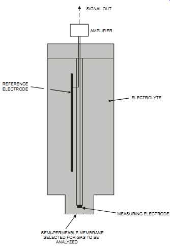
FIG. 26 Polarographic cell. MEASURING ELECTRODE SEMI-PERMEABLE MEMBRANE
SELECTED FOR GAS TO BE ANALYZED ELECTROLYTE REFERENCE ELECTRODE AMPLIFIER
SIGNAL OUT
===
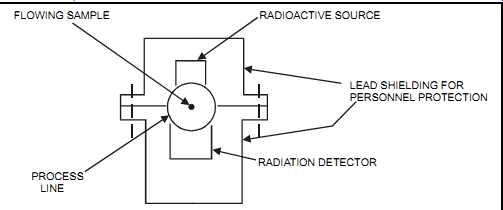
FIG. 27 Radiation absorption. FLOWING SAMPLE PROCESS LINE RADIOACTIVE SOURCE
LEAD SHIELDING FOR PERSONNEL PROTECTION RADIATION DETECTOR
===
Application Notes:
The radiation absorption method will measure the density of solutions, liquids, slurries, or finely divided solids. It’s applicable for clean as well as dirty fluids. The absorption unit is independent of the process conditions and therefore is not limited by process temperature and pressure. It’s also non-contacting and therefore the process must not be shut down to install it or perform maintenance. The radiation absorption unit gives continuous measurements, has an accuracy of +/- 1 percent of span, is highly sensitive, requires little maintenance (about 1 man week per year), and has a response time of about ten seconds. However, it’s expensive, requires about 30 minutes of warm-up time, and presents a radiation hazard. Exposing personnel to radiation is an ever present hazard of this method. All codes must be strictly followed, including obtaining a license, disposing of old units, and properly training personnel.
Rotating Disk Viscometer
Principle of Measurement:
The rotating disk viscometer consists of two concentric cylinders: a rotor and a stator. A single-speed synchronous motor rotates the rotor, while the stator senses viscosity by sensing the viscous drag as measured by a torsion element (see FIG. 28). The resistance to the rotation is a torque that is proportional to the shear stress of the fluid, which is then converted into a modulating signal. The multitude of shapes and sizes available for these rotors and stators, in addition to variations in rotating speed, make possible a wide range of measuring capabilities.
A temperature compensation method is commonly added to maintain a constant reference temperature while the process temperature changes.
Application Notes:
The rotating disk provides a measuring range of 50 to 25,000 centipoise (some units can even reach 720,000 centipoise). The disk has a typical accuracy of +/- 1 percent of span and a repeatability of +/-0.5 percent of span. It can operate from -40 to 300°F (-40 to 150°C) and up to 4000 psig (28,000 Kpag).
===
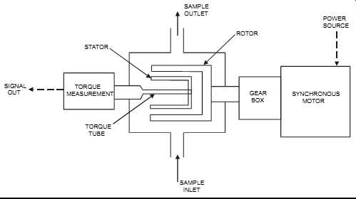
FIG. 28 Rotating disk viscometer. STATOR TORQUE MEASUREMENT TORQUE TUBE
SIGNAL OUT SAMPLE INLET GEAR BOX ROTOR SAMPLE OUTLET SYNCHRONOUS MOTOR
POWER SOURCE
===
Thermal Conductivity Detector (TCD)
Principle of Measurement:
The thermal conductivity detector (sometimes called a "katharometer") is based on the principle that different gases have different abilities to conduct heat. The detector measures the change in thermal conductivity of the sample gas versus a reference gas. The detector consists of heated temperature-sensitive (usually platinum) wires arranged in an elongated helix. Two wires are exposed to the sample and two to the reference gas. An equilibrium is reached when the electrical power input creates heat that is equal to the thermal loss from the wires. The temperature rise of the wire is inversely proportional to the thermal conductivity of the sample gas.
When the sample composition changes, the temperature of the heated wire changes as well, changing the resistance of the wire. This resistance change is proportional to the gas concentration. The sensors are part of a Wheatstone bridge circuit (see FIG. 29).
The thermal conductivity detector typically requires that the detector be supplied with a sampling system and a clean sample. Some units have a sealed reference gas chamber, which does not require a flowing reference gas. Thermal conductivity is not an absolute method and depends on empirical calibration. It’s also used as a detector in gas chromatography.
===
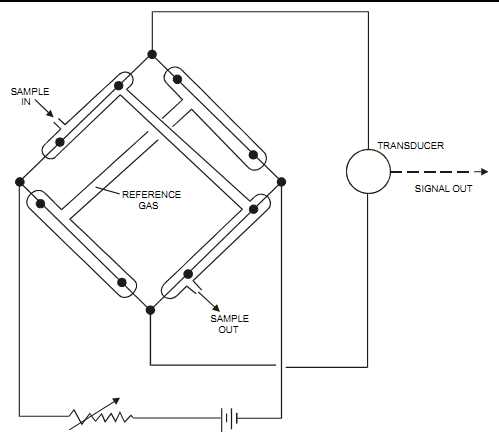
FIG. 29 Thermal conductivity detector with sealed reference chamber. SAMPLE
OUT REFERENCE GAS SAMPLE IN TRANSDUCER SIGNAL OUT
===
Application Notes:
The thermal conductivity detector is used for gases and vapors only. It has an accuracy of +/-1 to 5 percent of full scale, depending on the unit selected, and a response time of less than 30 seconds. It’s reliable and simple to use, but it generally requires either that water vapor be removed from the sample stream or that the sample be saturated at a constant temperature so as to minimize the effect of water vapor on the measurement of thermal conductivity. The thermal conductivity detector also requires a clean sample that is free from suspended particles so the sensing wires are not contaminated.
Ultraviolet
Principle of Measurement:
When ultraviolet (UV) light passes through a transparent material, some of the wavelength may be absorbed by the material. This selective absorption is the basis for UV analyzers. Light absorption is measured as a decrease in light intensity as a result of the interaction of the light energy with the absorbing material. The lost energy is converted into heat and/or chemical reactions. It’s possible to identify several absorbing components of a mixture on the basis of their individual pattern of absorption versus wavelength. The absorbance of a component is directly proportional to the material concentration that causes the absorption; that is, the amount of radiation transmitted by the component decreases as the concentration increases.
Many materials don’t absorb UV, such as water, CO, CO2, N2, and O2. Others, such as sulfur containing compounds, strongly absorb UV radiation.
The ultraviolet (UV) analyzer applies the Lambert-Beer law. It consists of a light source, a wavelength isolator (i.e., a filter), a sample cell, and a detector. A basic single-beam UV analyzer is shown in FIG. 30.
When heat is applied to a material, radiant energy is emitted. The light source produces the radiant energy and consists of a long-life gas-discharge lamp that emits fixed wavelengths in the near-UV region of the spectrum (from 200 to 380 nanometers). The UV region has shorter wavelengths than those associated with visible light.
The wavelength isolator is basically an optical filter (or a holographic grating) that allows radiation to pass through the cell. The measuring filter is typically a narrow-band-pass filter that is chosen so only the wavelength of the component to be measured is allowed through. When a reference filter is used, it’s selected to act as a narrow-band-pass filter that prevents the measured or background components from absorbing the radiation. The reference filter compensates for changes in radiation so as to maintain accuracy of the analyzer. Optical filtering can be located before or after the sample.
The sample cell is generally cylindrical with optical windows at both ends. Its purpose is to contain the sample and provide a flow path for the radiation from the light source to the detector. The windows are transparent at the chosen wavelength since different window materials will produce different wavelength regions. The cell must be mechanically and physically compatible with the sample being measured. The length of the cell varies from as small as 0.001" (0.025 mm) to as long as 6 ft (2 m).
The detector (with its transducer) measures the incoming radiation and converts it into an electrical output. The detector is selected based on the plant's sensitivity requirements and wave lengths.
There are different types of UV analyzers. The most common ones are the following:
1. The basic single-beam (see FIG. 30). These analyzers are simple in design, but their outputs are affected by fluctuations and drifts of the light source and by dirt in the sample cell. They are used for low-sensitivity measurements such as go/no-go applications.
===
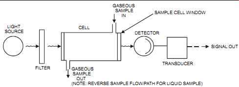
FIG. 30 Basic single-beam UV analyzer. LIGHT SOURCE FILTER CELL GASEOUS
SAMPLE OUT (NOTE: REVERSE SAMPLE FLOW/PATH FOR LIQUID SAMPLE) TRANSDUCER
DETECTOR GASEOUS SAMPLE IN SAMPLE CELL WINDOW SIGNAL OUT
===
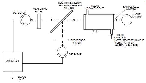
FIG. 31 Dual-beam, dual detector, UV analyzer. DETECTOR MEASURING FILTER
AMPLIFIER SIGNAL OUT DETECTOR 50% TRANSMISSION SEMI-TRANSPARENT MIRROR
LIQUID SAMPLE OUT CELL REFERENCE FILTER LIQUID SAMPLE IN (NOTE: REVERSE
SAMPLE FLOW PATH FOR GASEOUS SAMPLE) SAMPLE CELL WINDOW LIGHT SOURCE
===
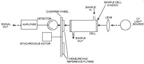
FIG. 32 Single-beam, dual-wavelength, single detector, UV analyzer. SIGNAL
OUT AMPLIFIER DETECTOR SYNCHRONOUS MOTOR CHOPPER WHEEL SAMPLE IN CELL
SAMPLE OUT SAMPLE CELL WINDOW LENS UV LIGHT SOURCE MEASURE AND REFERENCE
FILTERS
===
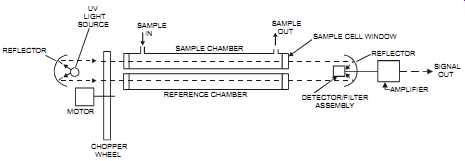
FIG. 33 Dual-beam, dual-chamber, single detector, UV analyzer. UV LIGHT
SOURCE REFLECTOR MOTOR SAMPLE IN SAMPLE CHAMBER SAMPLE OUT REFERENCE CHAMBER
CHOPPER WHEEL SAMPLE CELL WINDOW DETECTOR/FILTER ASSEMBLY REFLECTOR AMPLIFIER
SIGNAL OUT
===
2. The dual-beam, dual detector (see FIG. 31). In these analyzers, the beam is split by a semitransparent mirror. One beam goes through the sample while the other is used as a reference. These units are simple in design and easily manufactured; however, separate filters and optical trains create signal imbalances and zero drifts.
3. The single-beam, dual-wavelength, single detector (see FIG. 32). In these units, a chopper motor rotates the filter wheel, exposing filters alternately to the beam's path reference. The measure filter is selected to allow only one wavelength through, that of the component to be measured. These units are more stable then the dual-beam, dual detector type.
4. The dual-beam, dual-chamber, single detector (see FIG. 33). In these analyzers, the light source, reflecting from a conical front mirror, splits into two beams. A chopper wheel alternately blocks the beam to the sample and reference chambers. When the beam passes through the reference chamber, no absorption occurs. However, when the beam passes through the sample, absorption does occur and is sensed by the filter/detector assembly.
The filter is selected so as to allow through only the wavelength for the component to be measured. These units are relatively stable.
Application Notes:
The ultraviolet (UV) analyzer will measure liquids, gases, vapors, and sometimes thin-film solids. It’s rugged, provides a continuous measurement, and does not have many of the limitations applicable to infrared analyzers due to the relatively high energy level associated with UV. Most of the problems encountered in this method involve the sampling system rather than the UV analyzer itself.
UV analyzer units don’t require that moisture be removed from the incoming sample, which results in a simpler system that does not require special condensers. These units have a typical error of +/- 1 to 2 percent of full scale and can measure concentrations down to 2 ppb for a 0 1000 ppb range. They can handle sample pressures up to 3000 psig (21000 Kpag) with special windows and temperatures up to 1000°F (538°C), but are generally limited to 100 psig (700 Kpag) and 140°F (60°C). The UV analyzer is easy to maintain. It requires about one to two man-weeks per year for maintenance. It meets CFR 40 Part 60 and 75 when measuring SO2, NO, NO2, and NOx. It also meets CFR 40 Part 266 when measuring Hg. For liquid applications, the analyzer's sample cell should be arranged so that the flow enters at the bottom and exits at the top to prevent gas bubbles from being trapped. For gas applications, the analyzer's sample cell should operate such that the flow enters at the top and exits at the bottom to prevent liquids and solids from being trapped. The UV analyzer has a response time of 0.5 to 120 seconds, depending on the length of the analyzer cell path length and on the sample being analyzed. However, it does require a clean sample and is relatively expensive. Moreover, its light source can cause photo chemical reactions, which can sometimes lead to dangerous conditions or maintenance problems.
Vibrating U-tube
Principle of Measurement:
The vibrating U-tube, which is used to measure density, consists of an electromagnetic circuit that supplies a transverse oscillation to a tube through a driver. As the liquid density changes, the measured frequency of oscillation, as detected by a pick-up element, will vary (see FIG. 34). This measurement is then converted into an output. Sometimes a straight rather than a U-tube is used, but the same principle of operation applies. Another way to describe this sensor is to compare it to a tuning fork whose frequency is determined by its material and shape. If the tuning fork is hollowed out and then filled with a liquid, that liquid will determine the tuning fork's vibrating frequency.
Some definitions:
• Density = mass per unit volume of a liquid
• Specific gravity = ratio of the liquid density being measured to the density of water (with the temperature of both liquids stated)
===
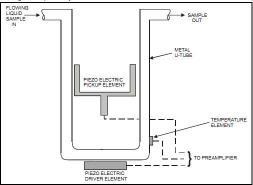
FIG. 34 Vibrating U-tube liquid-density meter. FLOWING LIQUID SAMPLE IN
SAMPLE OUT METAL U-TUBE PIEZO ELECTRIC DRIVER ELEMENT TEMPERATURE ELEMENT
TO PREAMPLIFIER PIEZO ELECTRIC PICKUP ELEMENT
===
Application Notes:
The vibrating U-tube is very reliable and accurate (up to 0.00015 g/cc), is unaffected by variations in viscosity and flow, and does not require frequent calibration (once every two years is average). It’s used mainly to measure liquid density (or specific gravity), with process temperature and pressure ranges of up to 330°F (200°C) and 2000 psig (14000 Kpag). The vibrating U-tube requires a sample flow rate of 0.5 to 7 gpm (2 to 25 L/min). Offsetting its advantages, it’s expensive and neither initial setup or ongoing maintenance is simple. Temperature fluctuations are its greatest source of measurement error, and therefore, temperature compensation is required.
X-Ray Fluorescence Spectroscopy (XRF)
Principle of Measurement:
In the x-ray fluorescence spectroscopy (XRF) method, a known volume of the sample is subjected to a low-level radiation source from one of a range of sources, depending on the application. This causes each element in the sample to emit characteristic fluorescent x-rays (see FIG. 35). The intensity of these characteristic x-rays is proportional to each element's concentration. For solids, XRF provides essentially surface analysis. However, with lighter elements, the analysis can reach a penetration of up to ¼”. A computer is commonly attached to the XRF as an analytical system.
The XRF technique can analyze up to 36 elements, though more commonly 6, simultaneously.
XRF is typically used to measure metals in a variety of liquid and solid samples. Portable units are used particularly in remediating hazardous waste sites where contaminants such as lead, copper, zinc, nickel, mercury, and the like need to be detected. XRF is also used to analyze air borne particulates on filters.
===
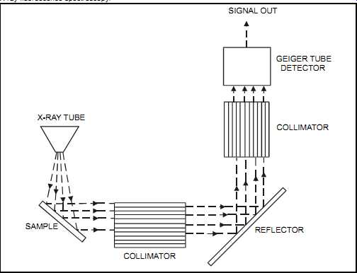
FIG. 35 X-ray fluorescence spectroscopy. X-RAY TUBE SAMPLE COLLIMATOR;
COLLIMATOR REFLECTOR GEIGER TUBE DETECTOR SIGNAL OUT
===
Application Notes:
The XRF technique measures solids, liquids, slurries, and powders. It has a typical range of 5 ppm (and down to 1 ppm for heavier elements) to 100 percent and is available in a battery powered field portable version. It provides continuous measurement, is easy to maintain, and is highly sensitive. The accuracy of its measurement depends on the particular element being analyzed and on the other elements that exist in the sample. Typically, an error of 1 percent is expected with this technique. On the other hand, it’s expensive and is usually not applicable to elements whose atomic weight is less than that of sulfur.
Zirconia Oxide Cell
Principle of Measurement:
The zirconia oxide cell consists of a solid electrolyte made of zirconium oxide ceramic. This material develops a potential difference (per the Nernst equation) between surfaces that are exposed to different concentrations of oxygen. On the inside and outside surfaces of the solid electrolyte, two porous platinum electrodes serve as conductors (see FIG. 36). Instrument quality dry air is used as a reference gas on one side of the cell while the other is exposed to the sample gas.
The measured voltage has a logarithmic response to oxygen concentration, with the greatest sensitivity at low concentrations since the cell output increases with a decrease in oxygen concentration. Typical ranges are 0 to 10 vol.% and 0 to 30 vol.% oxygen.
The zirconia oxide cell must be maintained at a temperature of 1110 to 1470°F (600 to 800°C), depending on the selected unit. The cell's performance is sensitive to temperature fluctuations.
To avoid significant errors, plants commonly use temperature sensors and heaters to maintain the set temperature.
===
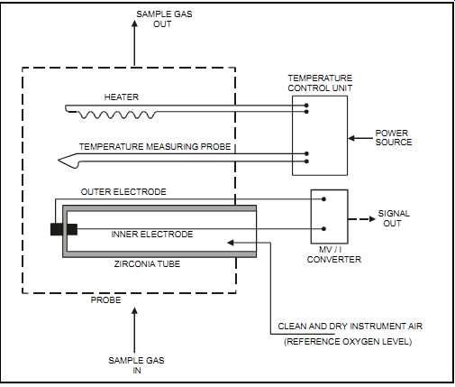
FIG. 36 Zirconia oxide cell. SAMPLE GAS; OUT HEATER TEMPERATURE MEASURING
PROBE TEMPERATURE CONTROL UNIT POWER SOURCE SIGNAL OUT OUTER ELECTRODE INNER
ELECTRODE ZIRCONIA TUBE PROBE SAMPLE GAS IN; MV / I CONVERTER CLEAN AND DRY
INSTRUMENT AIR (REFERENCE OXYGEN LEVEL)
====
Application Notes:
The zirconia oxide cell may measure oxygen in gas on a wet basis, whereas paramagnetic oxy gen measurement can only be done on a dry-gas basis. The cell has a response of 1 to 20 seconds (depending on the unit) and a typical accuracy of +/- 1 to 2 percent of full scale. It may be installed in line, thus avoiding the need for a sample line. The zirconia oxide cell is typically used in stack measurement; however, extractive types are used where extreme process conditions exist. These units are simple in design, meet CFR 40 Part 60 (Method 3A) when measuring oxygen, require relatively low maintenance (about two man days/year), and have a mean time-between-failures of about one to two years. Some zirconia oxide cell units can handle process temperatures of up to 3200°F (1760°C), but the operating pressure is typically limited to 10 in. (250 mm) W.C.
Zirconia oxide cell units are susceptible to breakage from mechanical shock and unburned organic contaminants (e.g., CO) will introduce error into the measurement. They may require the use of purge connections with periodic blowback to minimize plugging by entrained particles.